
Shielded Robot Cable for Robotics Applications with Braided Shield and Anti-Interference Design
Designed for robotics applications exposed to servo drives and VFD noise, this shielded robot cable maintains stable signal transmission under continuous bending and torsion. The combined foil and braided shielding structure ensures consistent EMI protection throughout long-term operation.
Key Benefits:
✅ Dual-layer shielding — stable EMI protection under motion
✅ Low transfer impedance — reliable signal integrity
✅ Torsion-resistant design — suitable for multi-axis robots
✅ PUR jacket — abrasion, oil, and hydrolysis resistant
Shielded Robot Cable for Robotics Applications with Braided Shield and Anti-Interference Design
Stable Signal Transmission Under Dynamic EMI Conditions
In robotic systems, signal errors are often caused by electromagnetic interference rather than mechanical failure. Servo drives, variable frequency drives (VFDs), and switching power supplies generate continuous noise that affects signal stability—especially under motion.
In real applications, shielding performance must remain stable at the flex point, not just in static conditions. This cable is designed to maintain consistent transfer impedance throughout its service life, even under repeated bending and torsion.
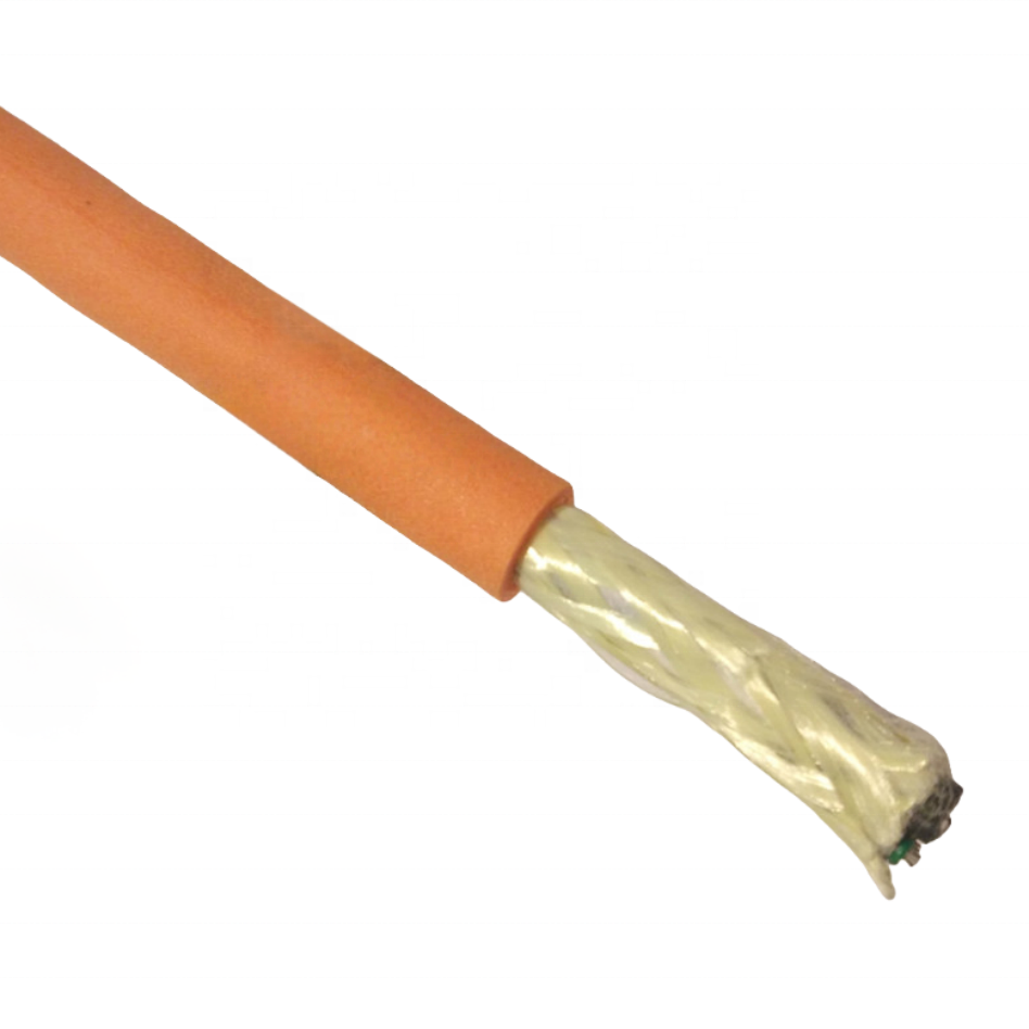
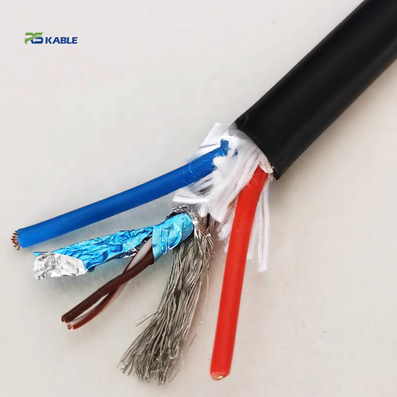
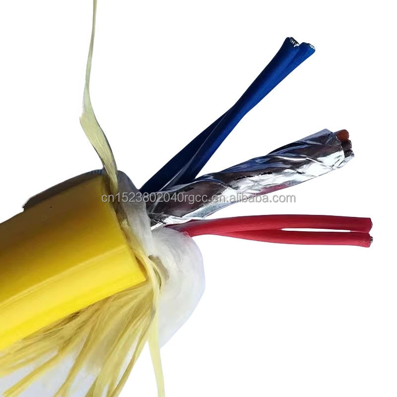
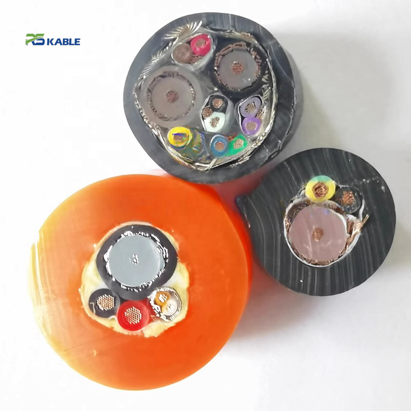
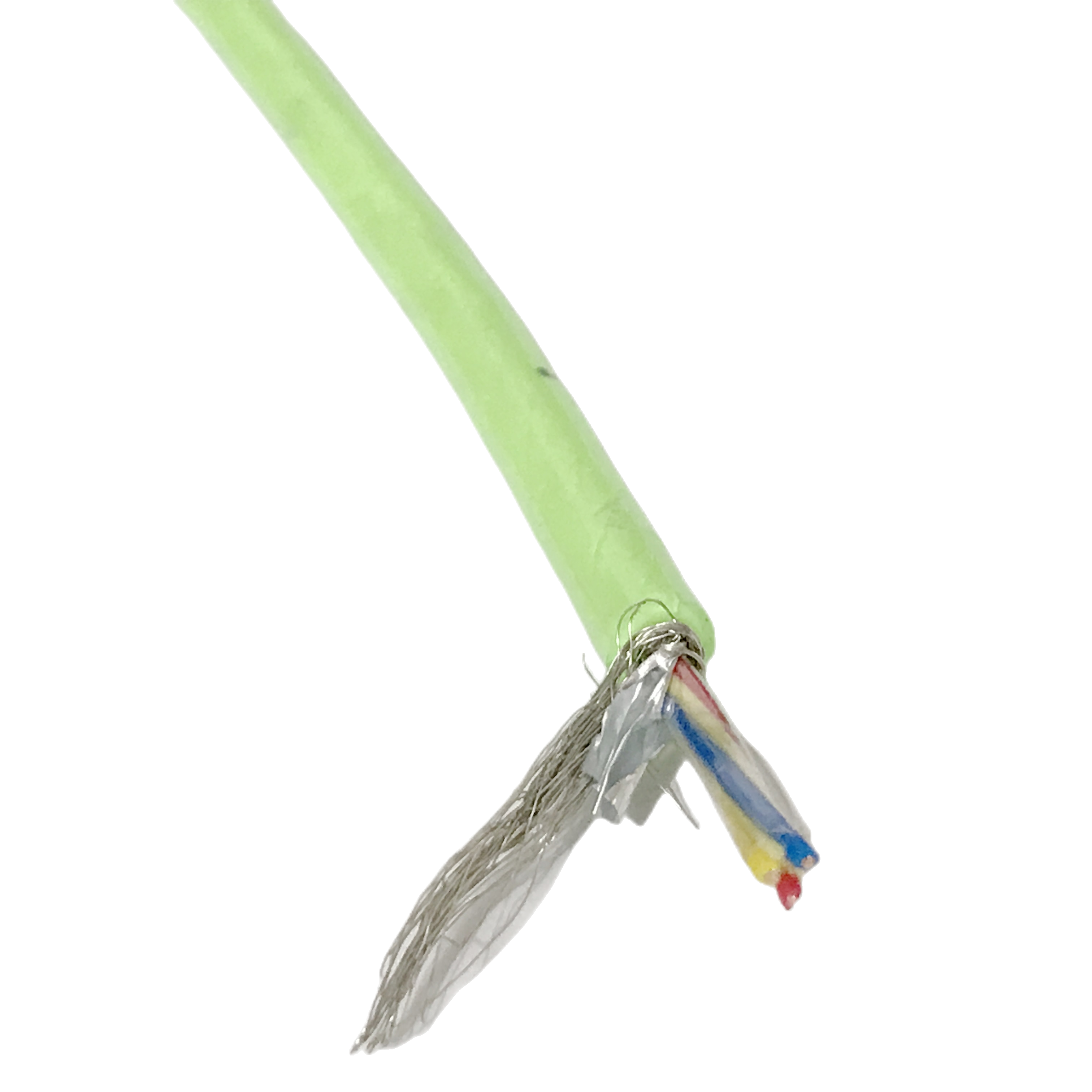
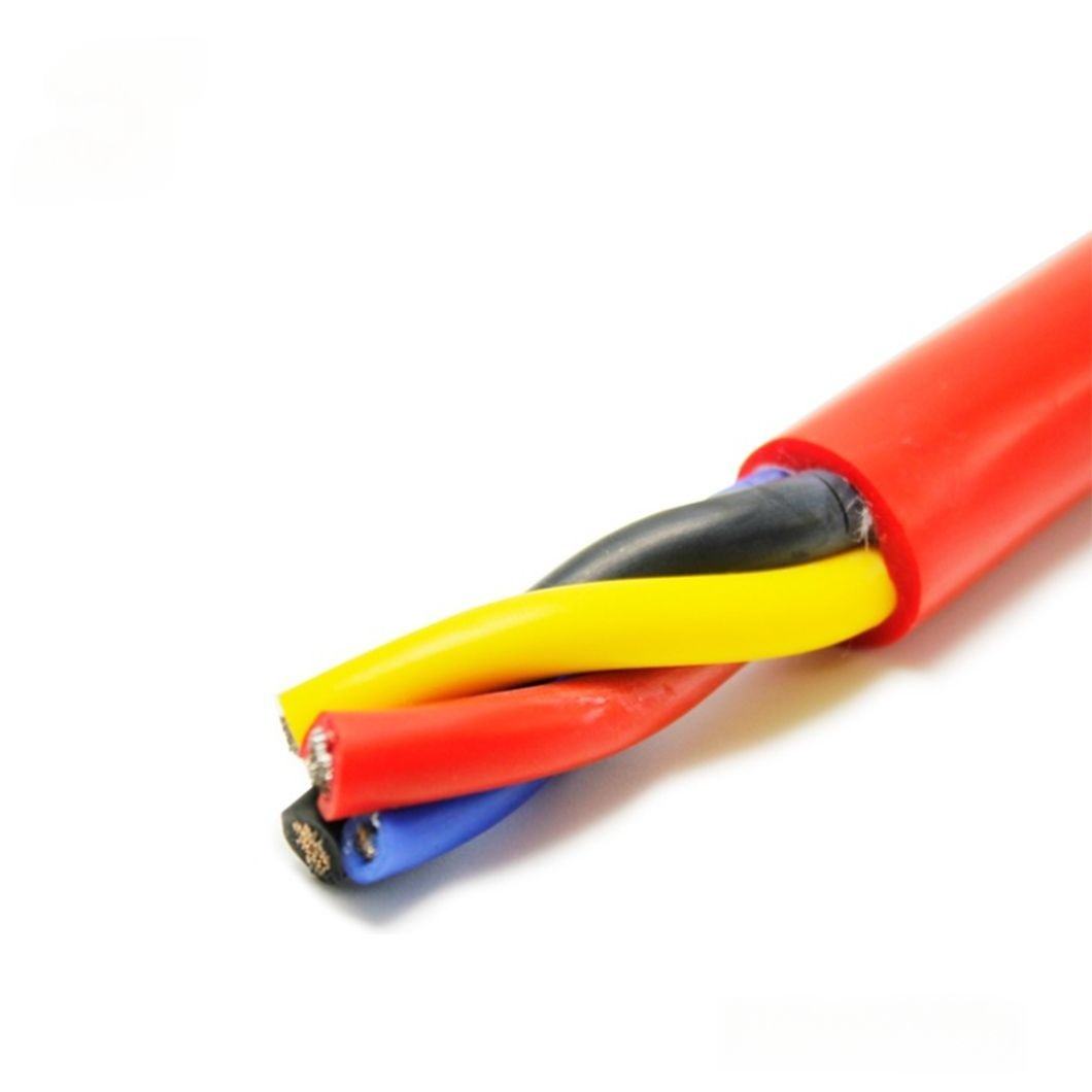
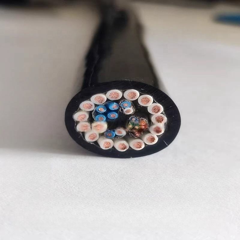
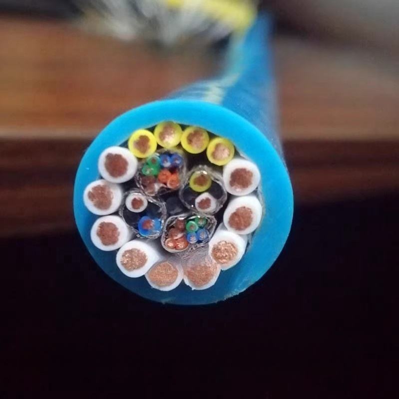
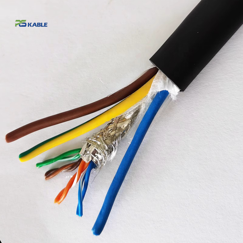
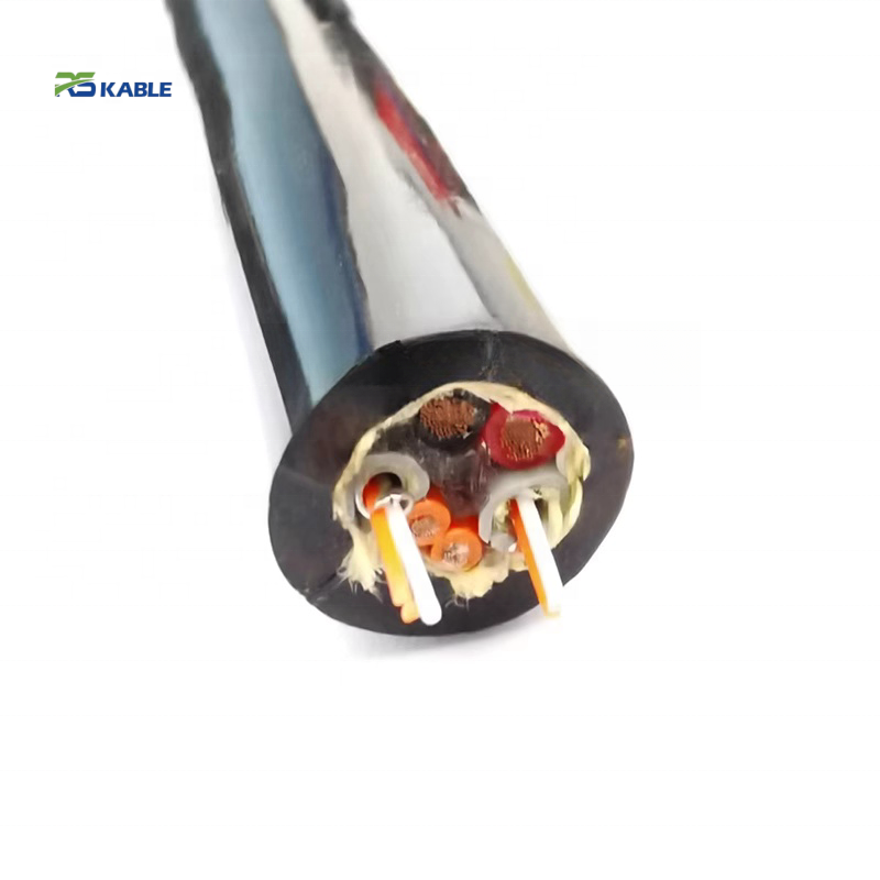
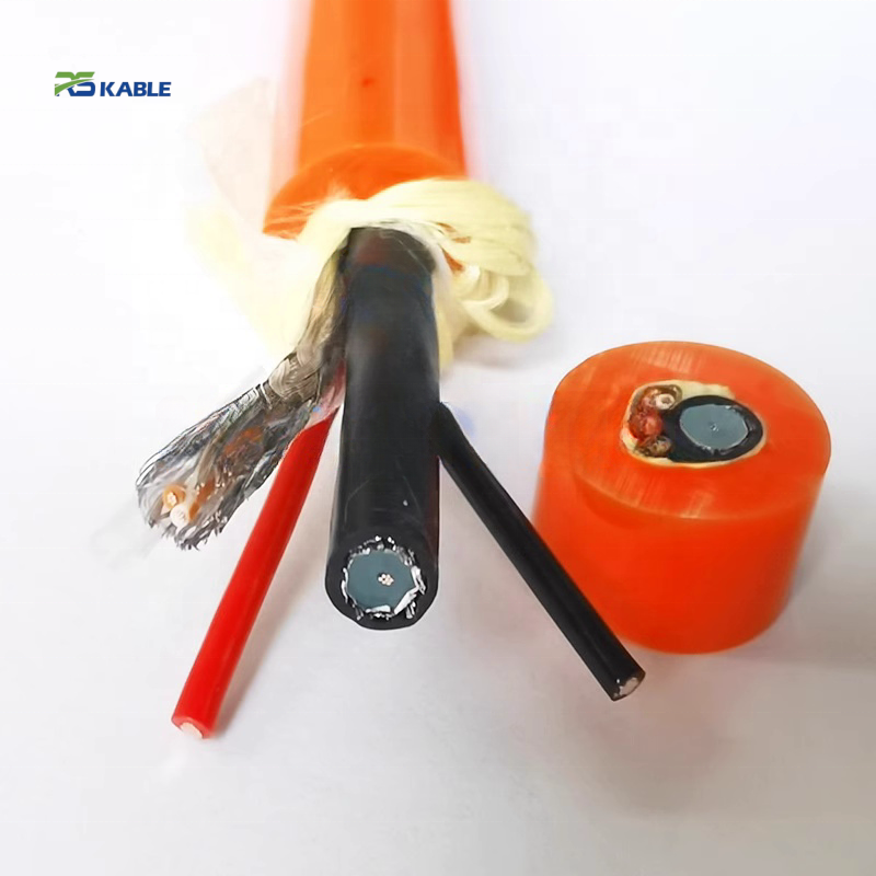
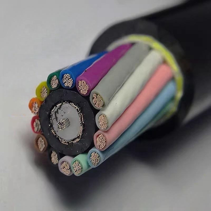
Shielding Architecture Designed for Motion
-
Foil Shield (AL/PET): suppresses high-frequency interference
-
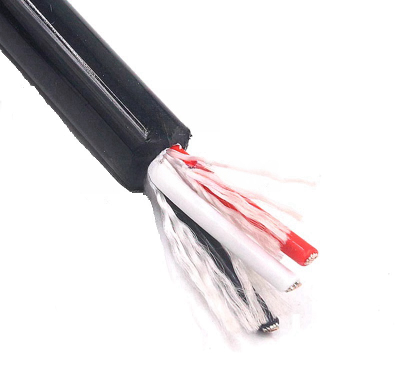
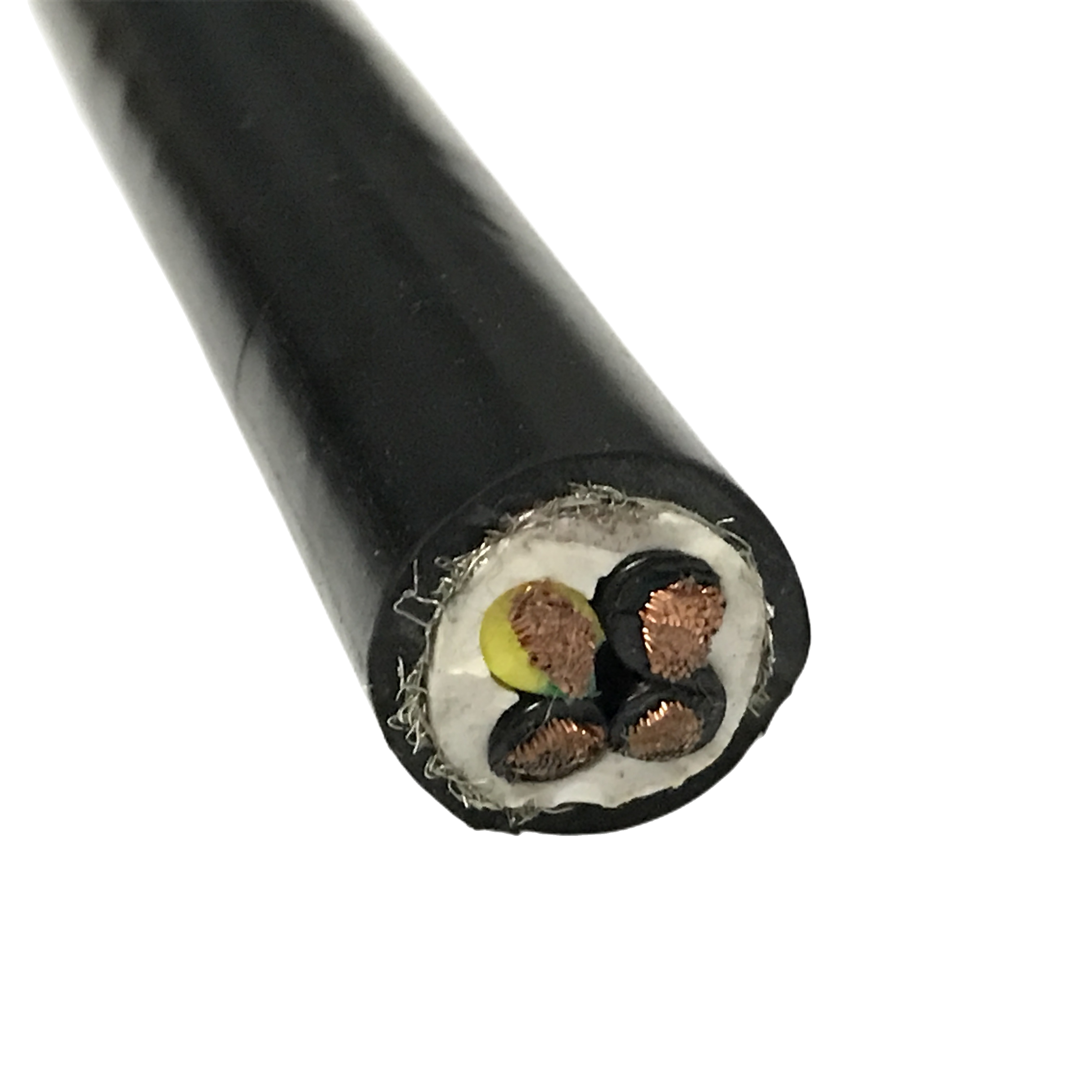
Braided Copper Shield (≥85% coverage): stabilizes low-frequency noise
-
Bonded Drain Wire: maintains electrical continuity under torsion
This dual-layer structure ensures reliable EMI/RFI protection across the full frequency range encountered in robotic systems.
Measured Electrical & Mechanical Performance
| Parameter | Specification |
|---|---|
| Transfer Impedance | ≤20 mΩ/m @ 1 MHz |
| Shield Stability | ≤28 mΩ/m after 5M flex cycles |
| Flex Life | ≥5,000,000 cycles |
| Torsion Capability | ±180°/m |
| Bend Radius | 6–8 × OD |
| Temperature Range | −40°C to +90°C |
| Jacket Material | Polyether PUR |
All shielding values are verified at dynamic flex positions rather than straight cable sections.
Common Failure Modes in Shielded Robot Cables
Shield Breakage at Flex Points
Repeated bending can lead to fatigue of braid wires, reducing shielding continuity.
Design approach:
Braid angle is controlled within 32–38° to balance flexibility and coverage.
Drain Wire Separation Under Torsion
In twisting applications, unrestrained drain wires may detach from the shielding layer.
Design approach:
Drain wire is bonded at defined intervals to maintain electrical path stability.
EMI Leakage from Incomplete Coverage
Low shielding coverage results in unstable EMI protection.
Design approach:
High-coverage braid combined with foil shielding provides full-spectrum protection.
Jacket Wear in Dynamic Environments
Oil exposure and mechanical contact accelerate material degradation.
Design approach:
Ether-based PUR resists abrasion, oil, and hydrolysis over long service periods.
Braided Shield vs Foil Shield in Robot Cables
| Shield Type | Strength | Limitation | Typical Use |
|---|---|---|---|
| Foil (AL/PET) | High-frequency shielding | Prone to cracking under flex | Data / encoder signals |
| Braided Copper | Flex durability, low-frequency stability | Limited high-frequency shielding | Power / control circuits |
| Foil + Braid | Full-spectrum shielding | More complex structure | Robotics, servo systems |
Under repeated motion, foil-only shielding may degrade after extended cycles, while braided structures maintain continuity more effectively.
Engineering conclusion:
For robotic systems with servo or VFD interference, combined shielding provides more stable long-term performance than single-layer shielding.
Where Shielded Robot Cable Is Required
| Application Environment | EMI Source | Shield Requirement |
|---|---|---|
| Material handling robot | Minimal interference | Not required |
| Servo-driven system | PWM noise | Required |
| Welding robot | Arc interference | Mandatory |
| Encoder feedback system | High sensitivity | Mandatory |
| Collaborative robot (cobot) | Mixed environment | Recommended |
In many cases, signal instability appears before visible cable damage, particularly in high-precision systems.

Shield Performance Metrics That Matter in Motion
| Parameter | Significance |
|---|---|
| Transfer Impedance | Indicates shielding effectiveness |
| Stability After Flex Cycles | Determines long-term reliability |
| Braid Coverage (%) | Affects EMI leakage resistance |
| Torsion Stability | Ensures shielding continuity under twist |
| Test Position | Must be measured at flex point |
Static test data alone does not reflect real operating conditions. Performance must be validated under dynamic movement.
Application Matching
| Application | Requirement | Recommended Configuration |
|---|---|---|
| Robot wrist joints | High torsion + EMI | Double shielded cable |
| Welding robots | Strong interference | Foil + braid shield |
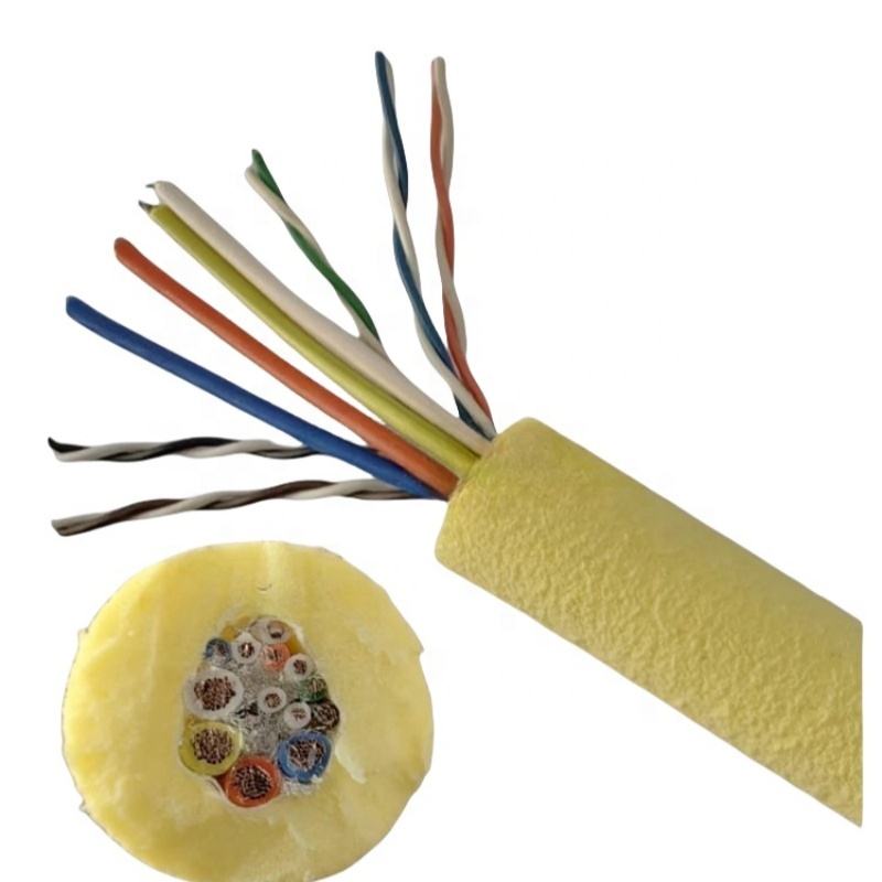
| Encoder systems | Signal precision | Enhanced shielding |
| High-speed robots | Continuous motion | High-flex PUR cable |
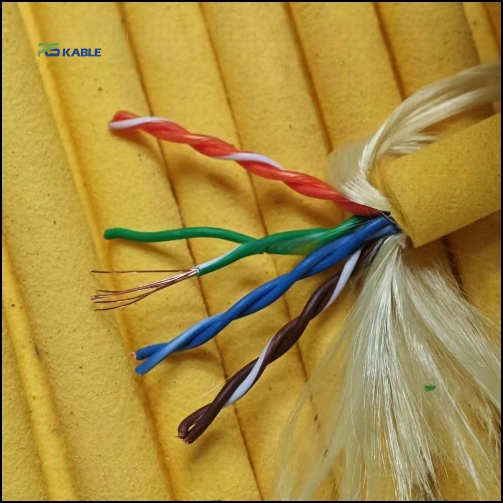
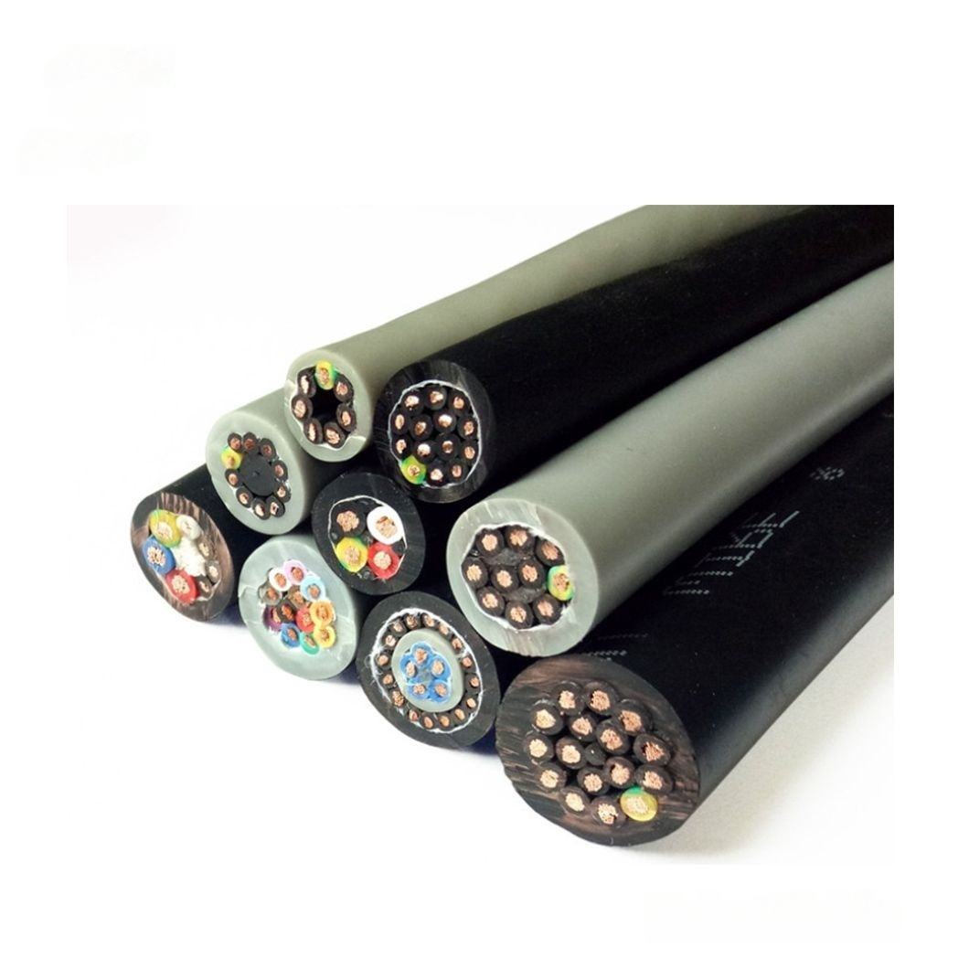
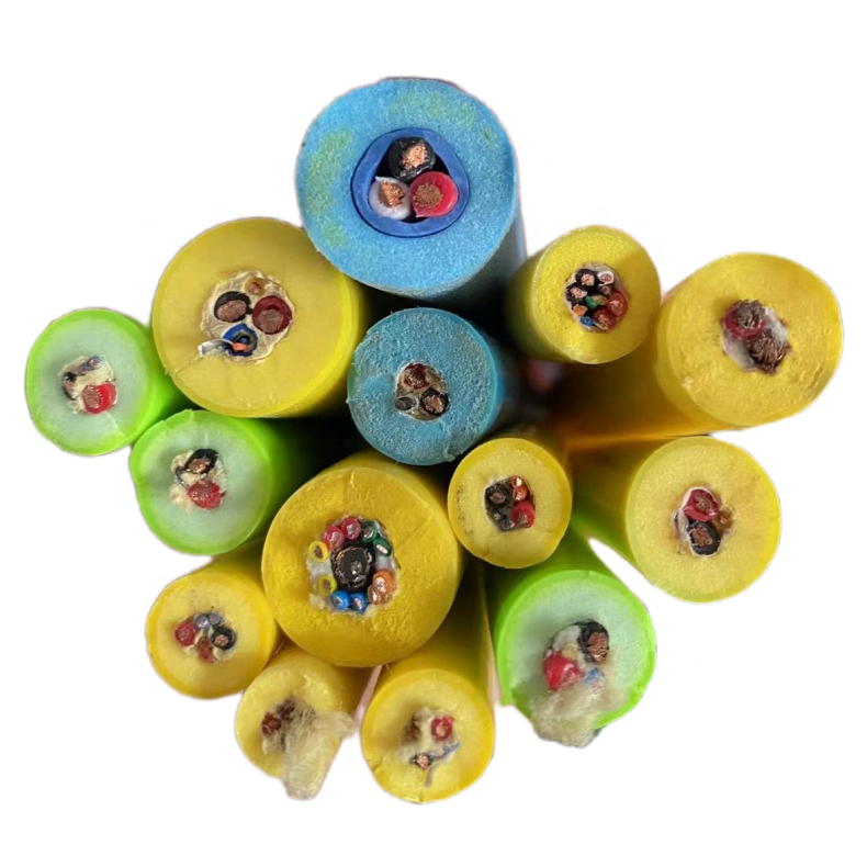
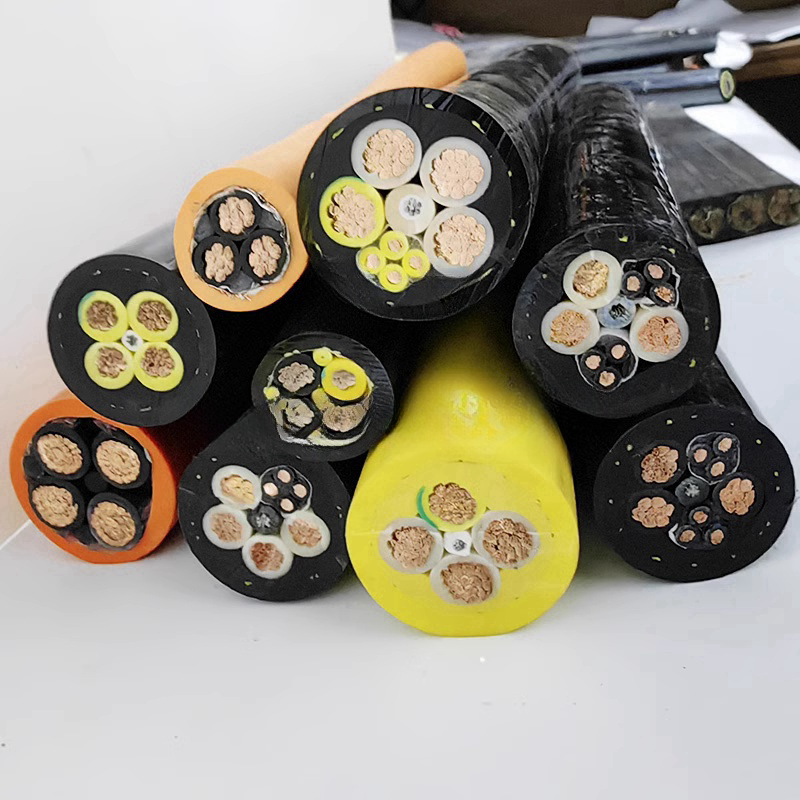
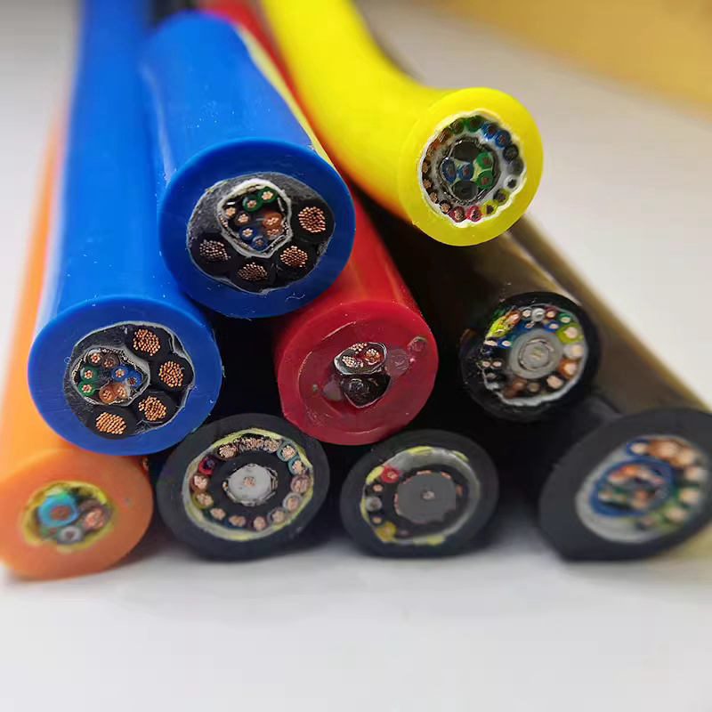
Available Configurations
-
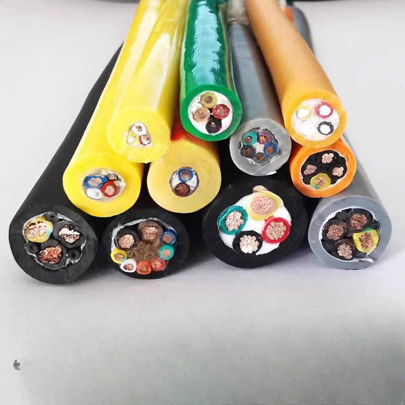
Core count: 2–36 cores
-
Cross-section: 0.14 – 2.5 mm²
-
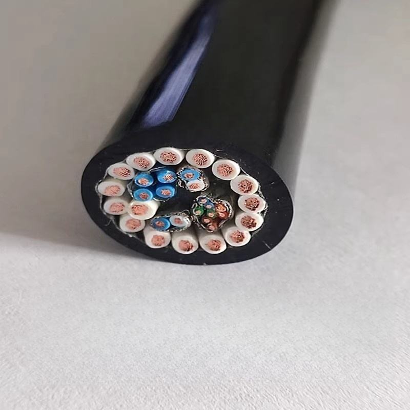
Shielding: single / double / encoder-grade
-
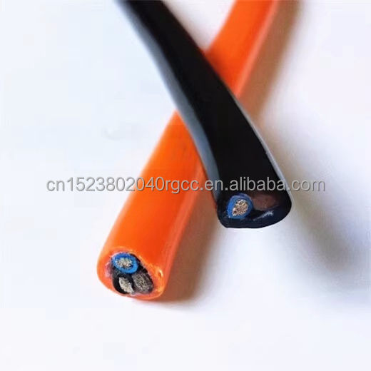
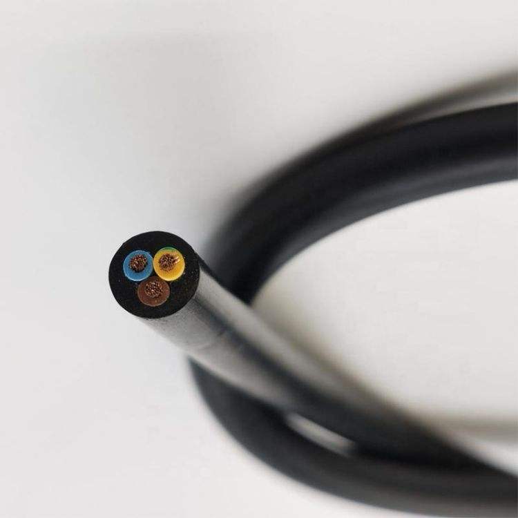
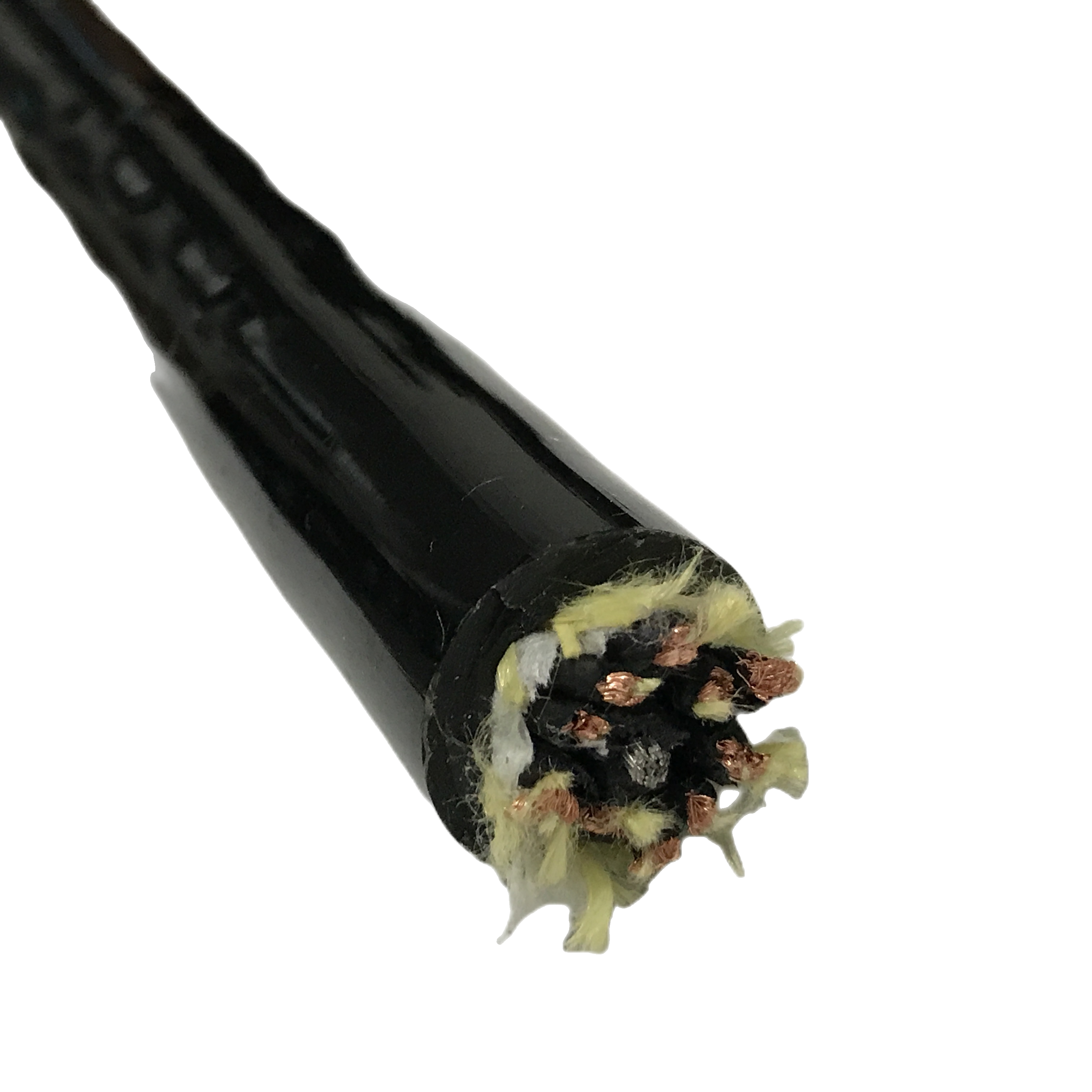
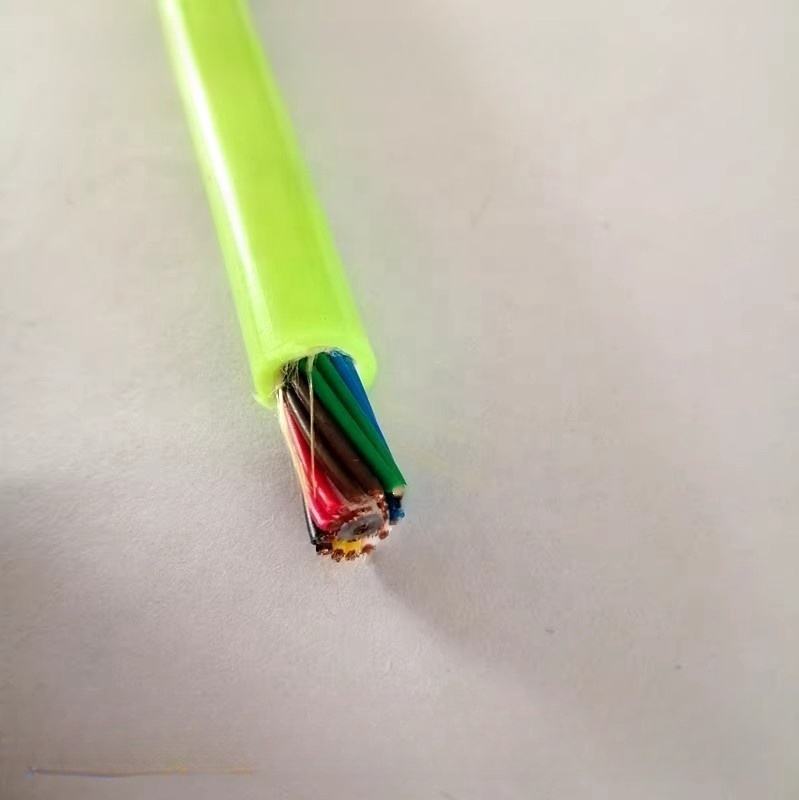
Structure: signal / hybrid (power + signal)
-
Jacket: PUR (standard), LSZH optional
Customization available for:
-
High-speed motion systems
-
Enhanced shielding performance
-
Compact or lightweight robot designs
Installation Considerations
-
Maintain torsion within specified limits
-
Ensure proper grounding of shield and drain wire
-
Avoid excessive compression at fixed points
-
Follow recommended bend radius
Improper installation is a frequent cause of early shielding degradation.
Typical Applications
-
Industrial robot arms (multi-axis systems)
-
Automotive welding lines
-
Servo-driven automation equipment
-
Precision encoder feedback systems
FAQ
What is the advantage of braided shielding in robot cables?
It maintains electrical continuity under repeated bending and torsion.
Why is transfer impedance important?
It directly reflects the cable’s ability to resist electromagnetic interference.
Is foil shielding alone sufficient?
Not in dynamic robotic systems—combined shielding is more reliable.
Why test shielding at the flex point?
Because mechanical stress concentrates at bending positions during operation.
Request Technical Matching
To determine the correct cable configuration, provide:
-
Robot type and motion characteristics
-
EMI environment (servo, welding, etc.)
-
Signal type (control, encoder, hybrid)
-
Installation conditions
Technical support is available for specification matching and custom design.