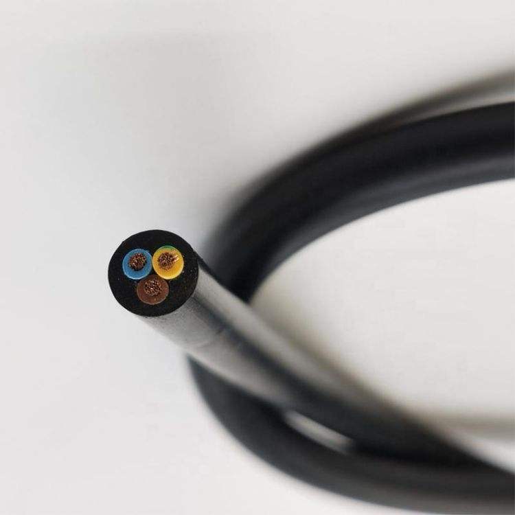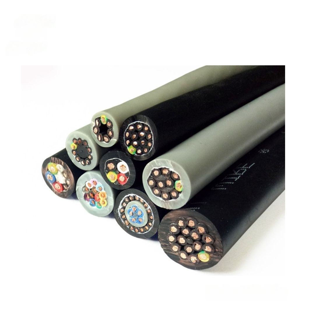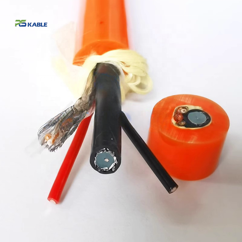

Industrial Robot Cable for Automation Systems Wiring with High Durability and Stability
Engineered for industrial automation systems, the RST-IA series maintains signal integrity through millions of flex cycles, with controlled resistance drift to ensure reliable long-term performance and predictable maintenance cycles.
Key Benefits:
✅ Class 6 conductors — stable performance with <2% resistance change
✅ Multi-level shielding — from standard I/O to encoder-grade applications
✅ Ether-based PUR jacket — oil resistant, hydrolysis-free, −40°C to +90°C
✅ LSZH clean-room and high-speed 10M cycle ETO options available
Industrial Robot Cable for Automation Systems Wiring with High Durability and Stability
Every industrial robot cable supplier claims long service life. The question that separates a validated claim from a marketing statement is: what measurement confirms it, and at what point in the cable’s life does the measurement fail? The RST-IA series answers this with three independently verifiable parameters: a < 2% resistance change limit through 5,000,000 flex cycles, a < 3.5% cross-section ovality limit, and a ≥ 100 MΩ insulation resistance floor at 1,000 V DC — all measured at the same flex checkpoint protocol, not at installation only.
This page is structured around those measurements. Section 1 documents the total cost consequence of selecting cable that does not meet these limits. Section 2 gives the construction parameters that determine whether the limits are achievable. Sections 3–5 provide the product matrix, a tier-selection decision framework with specific distance and signal-type boundaries, and a service-life calculator with a dual-axis correction factor for compound-loaded robot joints.
Section 6 documents resistance drift versus signal accuracy across the flex life — the data that allows a control engineer to predict measurement error at any point in the cable’s service, not just at end of life.
|
Flex life |
R stability |
Ovality limit |
Insulation R |
Jacket |
|
≥ 5,000,000 |
< 2% change |
≤ 3.5% |
≥ 100 MΩ |
PUR 90 Shore A |
|
cycles · 4–5× OD |
all 5M checkpoints |
cross-section at 5M |
at 1,000 V DC · 5M |
ether-type · oil/UV |

Why industrial robot cable specification is a profitability decision, not a procurement decision
Cable cost is 3–8% of the total cost of ownership in a high-cycle automation axis. The remaining 92–97% is downtime, labour, and fault diagnosis. The table below presents the 25-year cost comparison at three downtime rates — light industry (USD 600/h), automotive body shop (USD 1,500/h), and semiconductor fab (USD 5,000/h) — covering the realistic range of industrial automation environments.
Assumptions: Class 5 standard flex cable requires 3 replacements over 25 years in an axis cycling 200,000 times per year. RST-IA Class 6 requires zero replacements. Cable cost index: RST-IA = 100; Class 5 = 65 per replacement.
|
Cost element |
Class 5 — count |
Light industry (USD 600/h) |
Automotive (USD 1,500/h) |
Semiconductor (USD 5,000/h) |
|
Cable purchase cost (index) |
3 × 65 = 195 |
195 |
195 |
195 |
|
Planned downtime — replacement (4 h × 3) |
12 hours |
USD 7,200 |
USD 18,000 |
USD 60,000 |
|
Labour — pull, terminate, test (6 h × 3 × USD 80/h) |
18 hours |
USD 1,440 |
USD 1,440 |
USD 1,440 |
|
Unplanned fault downtime (1 event × 8 h) |
8 hours |
USD 4,800 |
USD 12,000 |
USD 40,000 |
|
Fault diagnosis labour (4 h × USD 80/h) |
4 hours |
USD 320 |
USD 320 |
USD 320 |
|
Total non-cable costs — Class 5 |
|
USD 13,760 |
USD 31,760 |
USD 101,760 |
|
RST-IA — total cost (cable only, no replacements) |
|
Index 100 |
Index 100 |
Index 100 |
|
RST-IA premium over Class 5 (index 35) pays back after how many hours of avoided downtime? |
|
35 ÷ USD 600 = 0.058 h — less than 4 minutes of avoided downtime |
35 ÷ USD 1,500 = 0.023 h — less than 2 minutes |
35 ÷ USD 5,000 = 0.007 h — less than 30 seconds |
The payback row is the key procurement argument: at any downtime rate above USD 100/h, the RST-IA’s cost premium pays back in avoided downtime before the robot arm completes its first hour of unplanned maintenance. The question for the procurement decision is not whether RST-IA costs more per metre — it does. The question is how many minutes of downtime justify the premium. At semiconductor fab rates, the answer is 30 seconds.
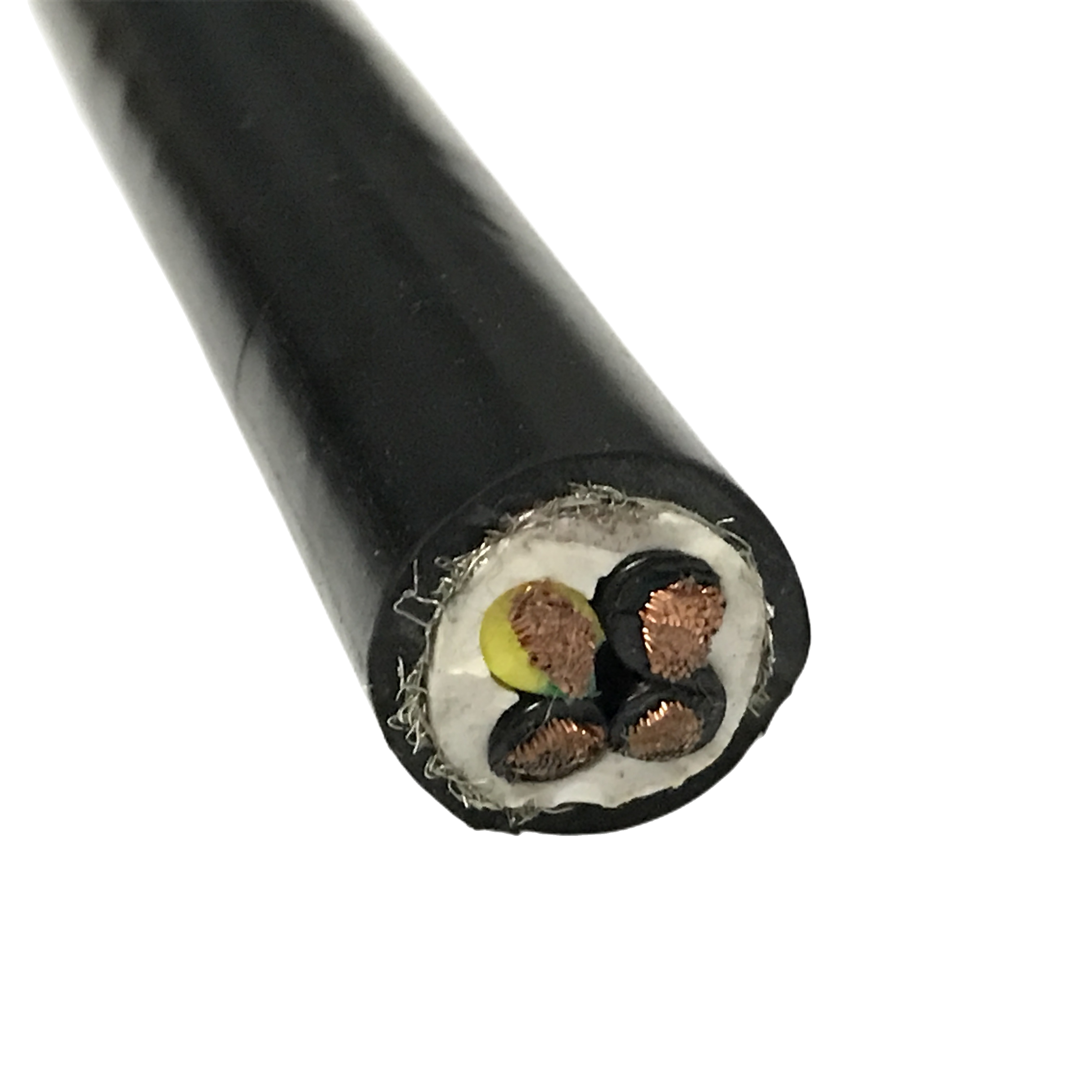
Construction Parameters and Measured Performance
Four validated construction parameters that determine industrial cable flex life
The following table maps each construction parameter to its specific failure mode, the validated specification for RST-IA, and the measured result at the 5M-cycle endpoint. All measurements use the same test protocol: single-axis flex at 4× OD, 0.5 m/s, 25°C ambient, per IEC 60227-2 modified.
|
Parameter |
Failure mode prevented |
RST-IA specification |
Measured result at 5M cycles |
|
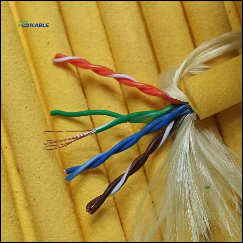
Conductor — Class 6, ≤ 0.10 mm wire |
Work-hardening fatigue fracture — wire stress above copper endurance limit at 4× OD |
≥ 196 wires / 0.75 mm²; lay 10–12× conductor OD |
DC resistance change: +1.6%. Zero conductor open-circuit events in any core. |
|
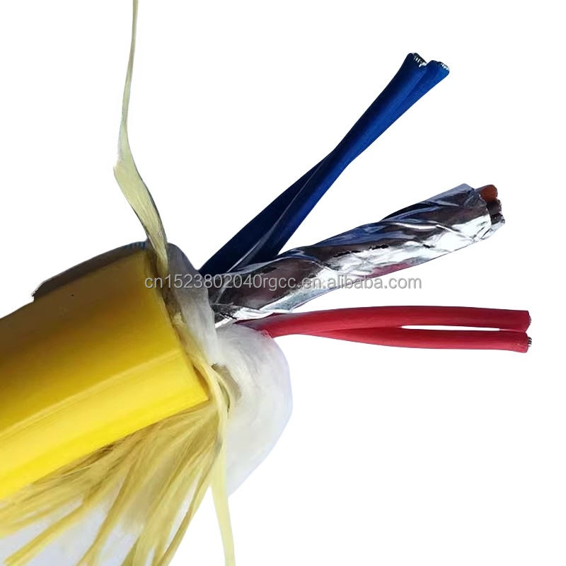
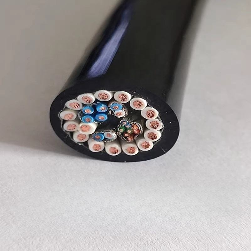
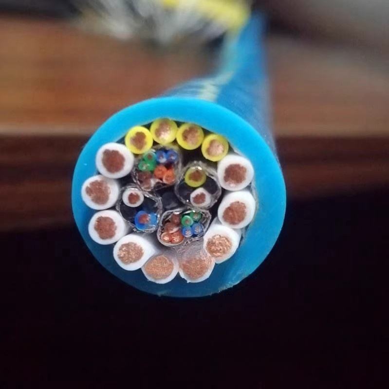
Core assembly — reverse-lay concentric stranding |
Layer binding (tightening) or unwinding under repeated flex — both increase effective stiffness |
Clockwise inner / counterclockwise outer; balanced torque design |
Cable OD change at flex mid-point after 5M cycles: +0.8% — within ±3% limit. No layer separation observed. |
|
Filler — foamed PE per core geometry |
Cross-section collapse to elliptical shape — outer cores travel longer differential path per cycle than inner cores |
Filler elements dimensioned to cable core count and OD; ovality limit ≤ 3.5% |
Cross-section ovality at 5M cycles: 3.1% — within ≤ 3.5% limit. |
|
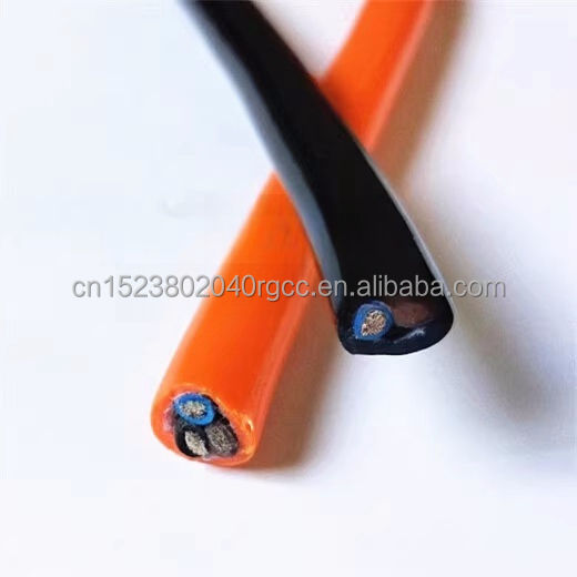
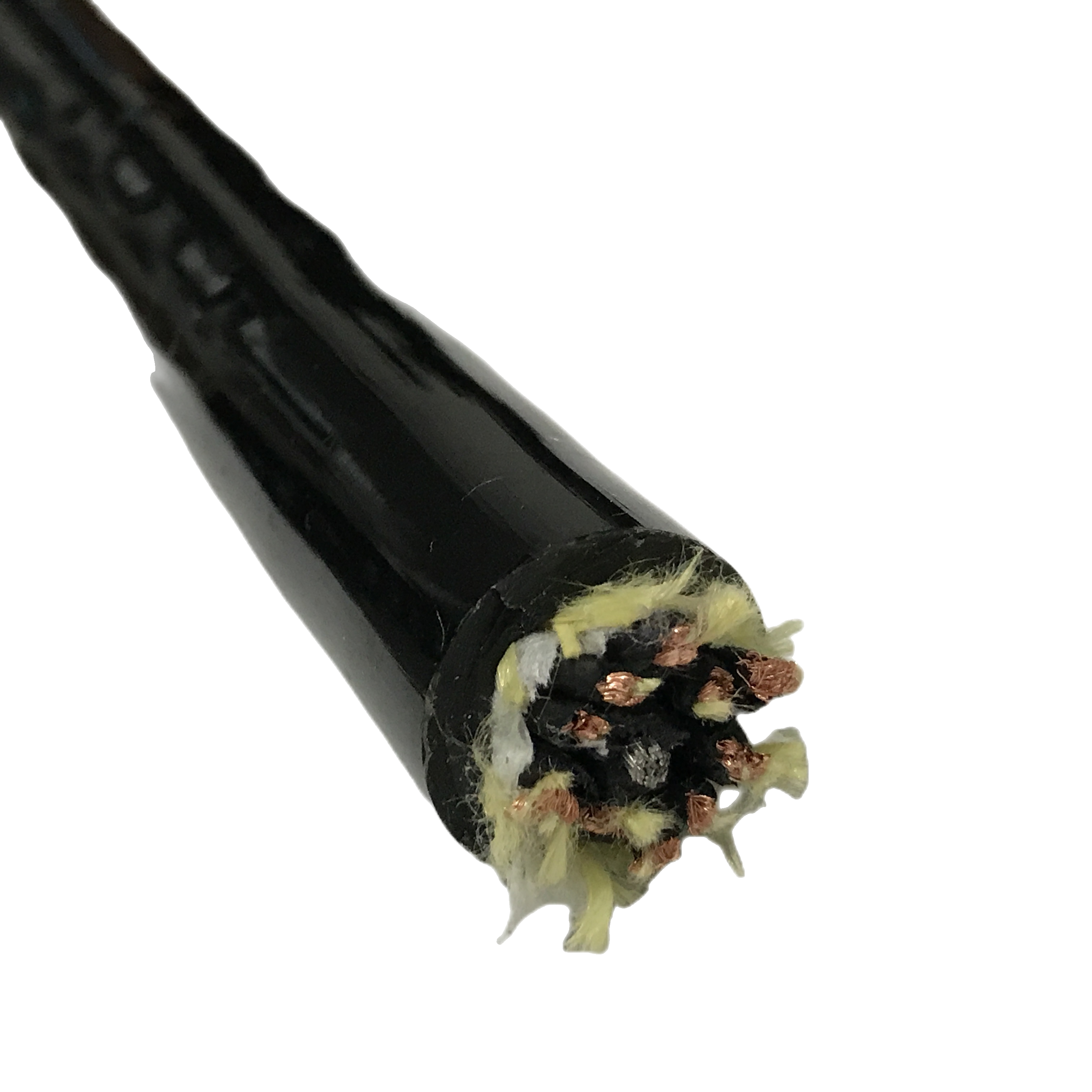
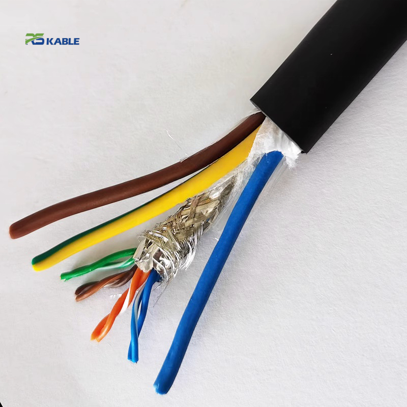
Jacket — ether-type PUR 90 Shore A |
Hydrolysis (ester-type): autocatalytic acid degradation in humid environments. Abrasion wear through to insulation. |
Ether-type PUR — no ester linkages; 90 Shore A balances abrasion and flex recovery |
Permanent set at 4× OD bend reversal point: 2.2% OD reduction — within ≤ 2.5% limit. No cracking at −40°C. |
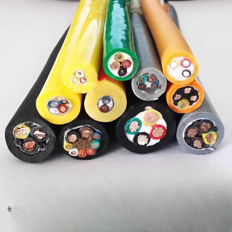
RST-IA Series Product Matrix
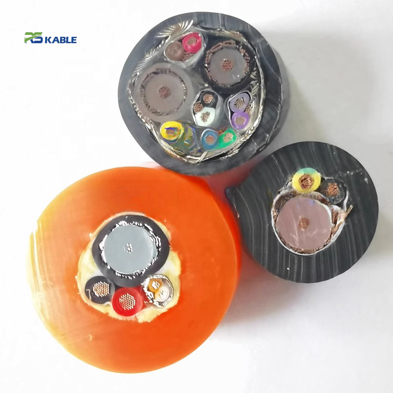
Industrial robot cable — all configurations with shielding tier and bend radius
All RST-IA models: IEC 60228 Class 6, ether-type PUR 90 Shore A, ≥ 5M flex cycles. Tier column (1/2/3) references the shielding selection framework in Section 4.
|
Model |
Tier |
Cores×mm² |
Shield |
OD (mm) |
Min bend R |
TI@1MHz |
Application |
|
RST-IA-110 |
1 |
4×0.34 mm² |
None |
5.5±0.3 |
4× OD = 22 mm |
— |
Limit switch, digital sensor |
|
RST-IA-120 |
1 |
4×0.75 mm² |
None |
7.0±0.3 |
4× OD = 28 mm |
— |
Control valve, 24 V DC I/O |
|
RST-IA-130 |
1 |
7×0.75 mm² |
None |
9.2±0.3 |
4× OD = 37 mm |
— |
Multi-signal arm wiring |
|
RST-IA-140 |
1 |
12×0.75 mm² |
None |
12.0±0.4 |
4× OD = 48 mm |
— |
Full I/O bundle (unshielded) |
|
RST-IA-210 |
2 |
4×0.34 mm² |
Cu braid overall |
7.0±0.3 |
5× OD = 35 mm |
<35 mΩ/m |
Digital I/O near VFD |
|
RST-IA-220 |
2 |
4×0.75 mm² |
Cu braid overall |
8.8±0.3 |
5× OD = 44 mm |
<35 mΩ/m |
Robot arm control — standard |
|
RST-IA-230 |
2 |
12×0.75 mm² |
Cu braid overall |
13.5±0.4 |
5× OD = 68 mm |
<35 mΩ/m |
Full I/O shielded, arm wiring |
|
RST-IA-240 |
2 |
3×1.5+4×0.75 |
Cu braid overall |
14.8±0.5 |
5× OD = 74 mm |
<35 mΩ/m |
Servo power + control combined |
|
RST-IA-310 |
3 |
2pr×0.14 mm² |
Foil/pr + braid |
6.5±0.3 |
5× OD = 33 mm |
<22 mΩ/m |
Encoder / resolver |
|
RST-IA-320 |
3 |
4pr×0.25 mm² |
Foil/pr + braid |
9.0±0.3 |
5× OD = 45 mm |
<22 mΩ/m |
Multi-encoder bundle |
|
RST-IA-330 |
3 |
2pr×0.75 mm² |
Foil/pr + braid |
9.8±0.3 |
5× OD = 49 mm |
<22 mΩ/m |
Analogue 4–20 mA in VFD env. |
|
RST-IA-C (ETO) |
1–3 |
Per spec |
Per spec |
4–22 mm |
Per OD |
Per spec |
10M cycle, LSZH, custom |
Tier colour guide: White rows = Tier 1 (unshielded). Sky-blue rows = Tier 2 (overall braid, TI < 35 mΩ/m). Lavender rows = Tier 3 (pair foil + braid, TI < 22 mΩ/m). See Section 4 for the distance-based selection boundary between tiers.
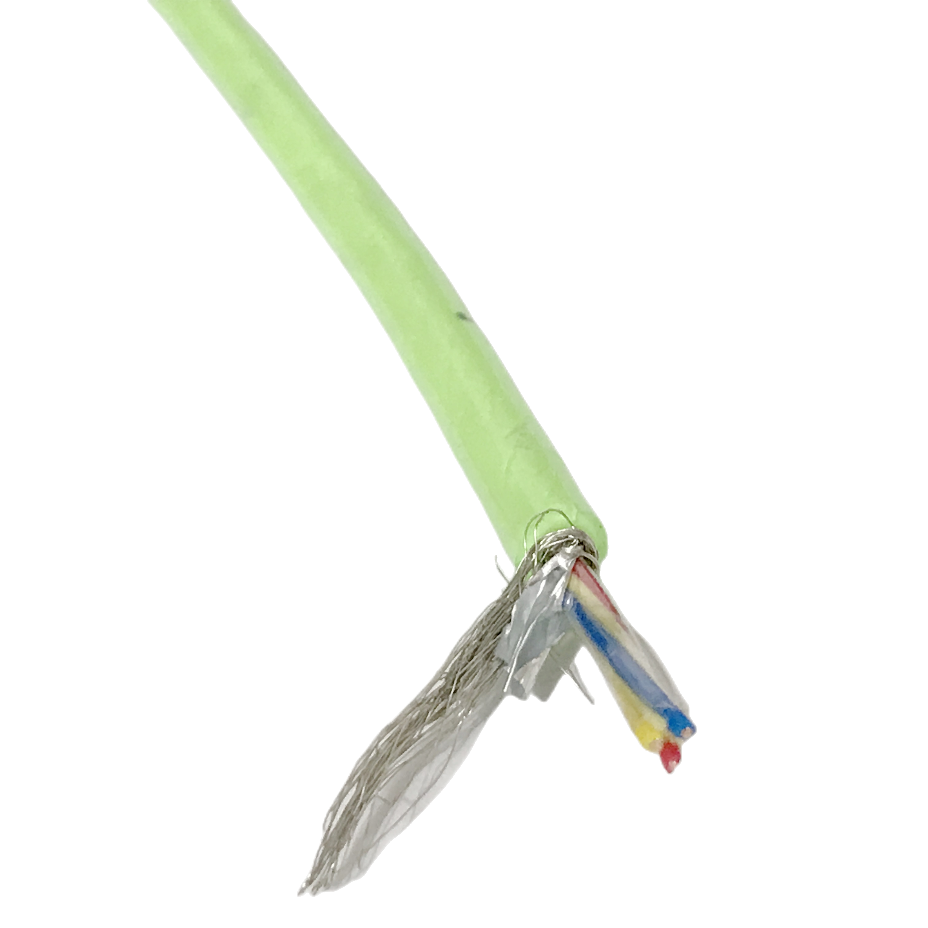
Shielding Tier Selection: Distance and Signal-Type Boundaries
How to select the correct industrial cable shielding tier for your automation wiring
The three RST-IA shielding tiers are not qualitative categories — they have specific, measurable trigger conditions. Using the wrong tier means either over-specifying (Tier 3 where Tier 1 is sufficient, adding OD and cost) or under-specifying (Tier 1 where Tier 3 is required, allowing signal errors that accumulate over the cable’s life). The following decision rules define the boundaries.
Tier 1 → Tier 2 boundary: the 300 mm distance rule
Upgrade from Tier 1 (unshielded) to Tier 2 (overall braid) when the industrial robot cable runs within 300 mm of a servo drive power cable, VFD output cable, or motor power cable — and there is no grounded metal barrier (cabinet wall, cable tray divider, or conduit) between the two cables.
The 300 mm threshold is based on magnetic field attenuation from an unshielded servo cable: at 300 mm distance, the field strength at the signal cable is approximately 40 dB below the source — below the noise floor of most 24 V DC digital I/O circuits. At 100 mm without a grounded barrier, the field is approximately 20 dB above the noise floor — Tier 2 shielding provides the additional 20 dB attenuation required.
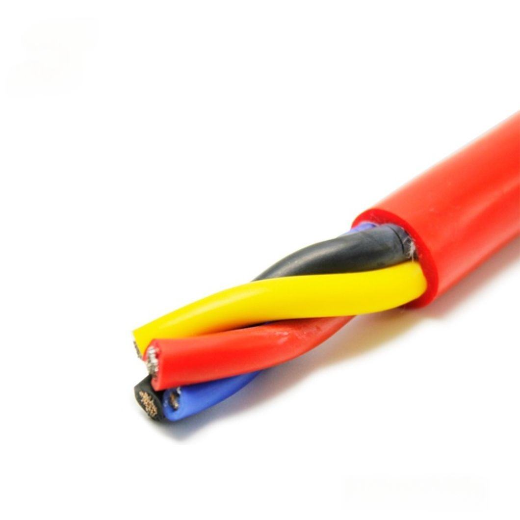
Tier 2 → Tier 3 boundary: signal sensitivity and frequency
Upgrade from Tier 2 (overall braid) to Tier 3 (pair foil + overall braid) when the signal is in one of these categories:
- Analogue 4–20 mA loop where the control loop accuracy requirement is ≤ 1% of full scale (the overall braid’s TI < 35 mΩ/m provides approximately 6–7% full-scale error margin at high cycle counts — adequate for ±2% loops, not for ±1% loops)
- Encoder or resolver signal at frequencies above 200 kHz — above this frequency, the individual pair foil provides 8–12 dB additional inter-pair isolation that prevents adjacent pair crosstalk from distorting edge timing
- Thermocouple wiring in a workcell with variable-frequency drives — thermocouple voltages (10–50 mV full scale) are 100–500× smaller than typical digital I/O voltage swings; even well-attenuated VFD noise exceeds the thermocouple signal level without pair-level shielding
Mixed-signal cables: when a single cable carries both Tier 1 and Tier 3 signals
When a cable carries both non-sensitive digital I/O (Tier 1 signals) and analogue or encoder signals (Tier 3 signals) in the same outer jacket, the entire cable must be specified as Tier 3. The pair foil on the analogue/encoder pairs provides isolation from the digital I/O cores within the same cable — this is the primary reason the Tier 3 pair-foil construction exists. Specifying Tier 2 for a cable carrying mixed signal types protects against external EMI but not against internal crosstalk between the digital and analogue/encoder cores.
|
TIER DECISION SUMMARY |
Tier 1 (unshielded): all cables > 300 mm from servo/VFD power cables, with digital-only signals (24 V DC I/O, limit switches, relay circuits). Tier 2 (overall braid): any cable within 300 mm of servo/VFD power cables, or > 300 mm but carrying analogue signals with ±2% or looser accuracy requirement. Tier 3 (pair foil + braid): analogue signals with ±1% or tighter accuracy; encoder/resolver at > 200 kHz; thermocouple wiring in VFD workcell; any cable carrying mixed digital and analogue/encoder signals in the same jacket. |

Service Life Calculator: Flex Cycles to Years with Compound-Load Correction
Industrial robot cable service life at your axis cycle rate — with dual-axis correction
The life calculator translates rated flex cycles into years of service for your specific axis cycle rate. The table includes a compound-load correction column for robot wrist joints (J4/J5) that flex simultaneously in two directions — an important correction that single-axis cycle counts alone do not capture.
Compound-load correction factor for dual-axis joints
At robot wrist joints J4 and J5, the cable bends in two planes simultaneously during most motion waypoints — not sequentially. The combined strain per motion cycle is approximately 1.5–2× the strain of single-axis bending at the same OD bend radius. Because fatigue life scales as (strain)^−3.5, a 1.5× strain increase reduces fatigue life to approximately (1.5)^−3.5 = 0.26× of the single-axis rating.
In practice, the cable does not spend 100% of its cycles in maximum dual-axis loading — the average compound factor for a typical 6-axis robot J4/J5 joint is approximately 1.35× the single-axis strain, producing a life correction factor of (1.35)^−3.5 ≈ 0.40×. The service life column for J4/J5 joints in the table below uses this 0.40× (40% of single-axis life) correction.
|
Application |
Cycles/hour |
Cycles/year (5,000 h/yr) |
RST-IA single-axis life |
RST-IA dual-axis life (×0.40) |
Class 5 single-axis comparison |
|
Conveyor divert arm |
60 |
300,000 / yr |
> 16.7 yr |
N/A — single axis |
1.7–5.0 yr |
|
CNC tool changer |
240 |
1,200,000 / yr |
> 4.2 yr |
N/A — single axis |
0.4–1.3 yr |
|
Welding robot — J2/J3 lower arm |
120 |
600,000 / yr |
> 8.3 yr |
N/A — near single axis |
0.8–2.5 yr |
|
6-axis robot — J4/J5 wrist (compound load) |
180 |
900,000 / yr |
5.6 yr (single-axis; not corrected) |
> 2.2 yr (×0.40 compound correction) |
0.3–0.8 yr |
|
SCARA robot — high speed |
600 |
3,000,000 / yr |
> 1.7 yr — ETO 10M recommended |
< 1 yr — use ETO |
0.2–0.5 yr |
|
Assembly robot — end-effector tether |
300 |
1,500,000 / yr |
> 3.3 yr |
> 1.3 yr (×0.40 for combined flex+extension) |
0.3–1.0 yr |
|
FORMULA AND CORRECTION |
Single-axis service life (yr) = Rated flex cycles ÷ (Cycles/hour × Operating hours/year) Dual-axis joint correction: multiply single-axis result by 0.40 for J4/J5 wrist joints under typical compound loading (1.35× average strain increase). 80% replacement rule: schedule replacement at 80% of calculated service life — at the next planned maintenance window, before end-of-life failure. Example: J4/J5 at 2.2 yr → replace at 1.8 yr from installation. High-speed applications exceeding 3M cycles/year: specify RST-IA-C ETO 10M-cycle variant; apply the same correction factors to the 10M base rating. |
Resistance Stability and Signal Accuracy Across Flex Life
How industrial robot cable resistance drift affects automation control accuracy
Resistance drift in an industrial robot cable is not an end-of-life event — it is a continuous process that affects signal accuracy from the first flex cycle. The practical consequence depends on the signal type carried by the cable.
Effect on 4–20 mA analogue signals
A 4–20 mA current loop signal uses the conductor resistance as part of the loop impedance. A 2% increase in conductor resistance shifts the loop current by approximately 0.13 mA at 20 mA full-scale — equivalent to 0.8% full-scale error. This is within the ±1% tolerance of most process instruments. A 15% increase (Class 5 at mid-service) shifts the current by 1.0 mA — equivalent to 6.3% full-scale error, above the ±0.5% accuracy specification of most closed-loop controllers.
Effect on encoder and resolver signals
Encoder and resolver cables are not affected by DC resistance drift in the same way — the signal is digital (pulse counting) rather than analogue (current level). However, conductor resistance interacts with the cable’s distributed capacitance to form a low-pass filter. As resistance increases, the −3 dB cutoff frequency of this RC filter decreases. At 15% resistance increase on a 100 m encoder cable, the cutoff frequency drops from approximately 2.5 MHz to 2.1 MHz — below the edge-rate requirement of some high-resolution absolute encoders at maximum traverse speed.
Resistance stability data by flex cycle checkpoint
|
Checkpoint |
RST-IA R change |
Class 5 R change |
4–20 mA full-scale error (RST-IA) |
4–20 mA full-scale error (Class 5) |
|
0 cycles (baseline) |
— |
— |
— |
— |
|
500,000 cycles |
+0.3% |
+2.1% |
0.02 mA · < 0.2% FS |
0.17 mA · 1.1% FS |
|
1,000,000 cycles |
+0.7% |
+6.5% |
0.06 mA · 0.4% FS |
0.52 mA · 3.3% FS |
|
3,000,000 cycles |
+1.2% |
+18% (if not failed) |
0.10 mA · 0.6% FS — within ±1% spec |
1.44 mA · 9% FS — outside ±0.5% spec |
|
5,000,000 cycles |
+1.6% |
N/A — cable failed |
0.13 mA · 0.8% FS — within ±1% spec |
Cable replacement required |
Field Diagnostic Reference: Failure Patterns in Automation Robot Cable
Identifying industrial cable failures by measurable symptom
These four failure patterns cover the large majority of robot cable faults reported to Rousheng’s field service team. The confirming measurement column identifies the specific instrument and test that separates cable failure from drive, sensor, or controller fault.
|
Symptom |
Root cause |
Confirming test |
Pass/fail threshold |
Correction |
|
Analogue signal drift — gradual, tied to flex cycle count on cycle counter |
Conductor resistance increasing — Class 5 work-hardening |
4-wire Kelvin resistance at flex mid-point vs straight section of same cable |
R increase > 5% at flex vs straight = work-hardening |
Replace with RST-IA. Use 80% life rule for scheduling: calculate service life from axis cycle counter, replace at 80% to avoid recurrence. RST-IA < 2% R change through 5M cycles — analogue error remains < 0.8% full-scale throughout rated life. |
|
Intermittent digital fault at specific arm position — repeatable |
Conductor micro-fracture at minimum bend radius — cable at end of Class 5 life |
Continuity test at fault position and at neutral position; compare resistance at both |
Resistance increase > 20% at fault position vs neutral = micro-fracture |
Replace with RST-IA. Check installation: verify bend radius at fault position ≥ 4× cable OD (unshielded) or 5× OD (shielded). If bend radius is adequate, the fault is conductor fatigue — use life calculator to set replacement schedule at 80% of calculated remaining life. |
|
EMI noise on analogue signal — proportional to servo motor load current |
Tier 1 cable within 300 mm of servo drive power cable without metal barrier |
Measure noise with motor drives enabled vs disabled; note if noise scales with motor load |
Noise > 3× with drives enabled vs disabled, scaling with load = EMI coupling |
Upgrade to Tier 2 (RST-IA-220) if cable is within 300 mm of servo/VFD power cable. Upgrade to Tier 3 (RST-IA-330) if signal is analogue 4–20 mA with ±1% accuracy requirement. Re-route to achieve ≥ 300 mm separation or add grounded metal divider — either approach eliminates the need for Tier upgrade. |
|
Jacket splitting or cracking — surface becoming tacky |
Ester-type PUR hydrolysis — autocatalytic acid degradation in humid/wet robot workcell |
Apply DI water to cracked surface and pH paper; measure surface condensate pH |
pH < 5.5 confirms acid hydrolysis product — ester-type PUR identified |
Replace with RST-IA ether-type PUR. Ester-type PUR is not identifiable visually or by flex test — pH confirmation at the crack surface is the only field method. When sourcing cables outside the RST-IA series, require written supplier confirmation of PUR chemistry type in purchase order terms. |
Frequently Asked Questions
How does the total cost of ownership calculation change for different industries using industrial robot cable?
The cable cost premium of RST-IA over Class 5 standard flex cable (approximately index 35) paybacks at any downtime rate above USD 100/h — this is true across all industries. What changes is how fast the payback occurs. At USD 600/h (light assembly), the premium pays back in 3.5 minutes of avoided downtime. At USD 1,500/h (automotive body shop), payback in 84 seconds. At USD 5,000/h (semiconductor fab), payback in 25 seconds. The cross-industry conclusion: the more the robot cell produces per hour, the less the cable cost difference matters and the more the replacement frequency matters.
What is the compound-load correction factor, and when do I apply it?
The compound-load correction factor (0.40×) applies to robot wrist joints J4/J5 that bend simultaneously in two directions during most motion waypoints. Single-axis flex life tests do not capture this combined loading. The 0.40× factor is derived from fatigue mechanics: a 1.35× average strain increase (typical for J4/J5 compound loading) reduces fatigue life by (1.35)^−3.5 = 0.40×. Apply the correction only to joints with genuine simultaneous multi-axis bending — J1/J2/J3 lower arm joints are near-planar flexors and do not require the correction.
When should I upgrade from Tier 2 to Tier 3 shielding?
Upgrade to Tier 3 (pair foil + overall braid) when the signal type is 4–20 mA analogue with ≤ ±1% full-scale accuracy requirement, encoder/resolver at frequencies above 200 kHz, or thermocouple wiring in any workcell with VFD or servo drive. The pair foil provides pair-level isolation that an overall braid alone does not — it attenuates inter-pair crosstalk within the cable as well as external EMI. For digital 24 V DC I/O signals, Tier 2 is always sufficient regardless of drive proximity, because 24 V digital signals have a 12 V noise margin that comfortably exceeds the residual noise after Tier 2 shielding.
How do I schedule cable replacement before failure without waiting for a fault?
Step 1: Read the axis cycle counter from the robot controller at installation. Step 2: Calculate service life using the formula (rated cycles ÷ cycles per year). Step 3: Apply the 0.40× correction for J4/J5 wrist joints. Step 4: Schedule replacement at 80% of the calculated service life — at the next planned annual shutdown after 80% of life is consumed. This approach converts cable maintenance from a reactive (failure-driven) event to a planned (shutdown-timed) event, eliminating unplanned downtime from cable end-of-life failures.
Request Samples, Flex Life Data, or a Quotation
Specifying the right industrial robot cable tier and variant for your automation system
Rousheng provides free application review — TCO calculation at your downtime rate, tier selection confirmation, service life calculation with compound-load correction, and bend radius check — before order placement.
For a complete first-reply response, include:
- Automation system type: robot arm (specify joint), drag chain, conveyor, SCARA, or other
- Axis cycle rate (cycles per hour) and annual operating hours
- Whether any axis is a dual-axis compound-load joint (robot wrist J4/J5 type)
- Signal types: digital I/O, analogue 4–20 mA (with accuracy spec), encoder (with frequency), or combined
- Distance from signal cable to nearest servo drive or VFD power cable, and whether a metal barrier exists
- Minimum bend radius available (conduit inner radius or drag chain inner radius)
- Environment: standard industrial, oil/coolant, clean-room (with ISO class), weld shop, or outdoor
- Downtime cost per hour at your facility (for TCO calculation in the application review)
- Quantity in metres or assembled cable sets with connector types
|
CONTACT |
Email: Jerry@rstlkable.com WhatsApp / Phone: +86 134 8219 7396 Address: No. 2591 Fengzhe Road, Fengxian District, Shanghai, China Sample requests: state RST-IA model, shielding tier, and automation system type. |