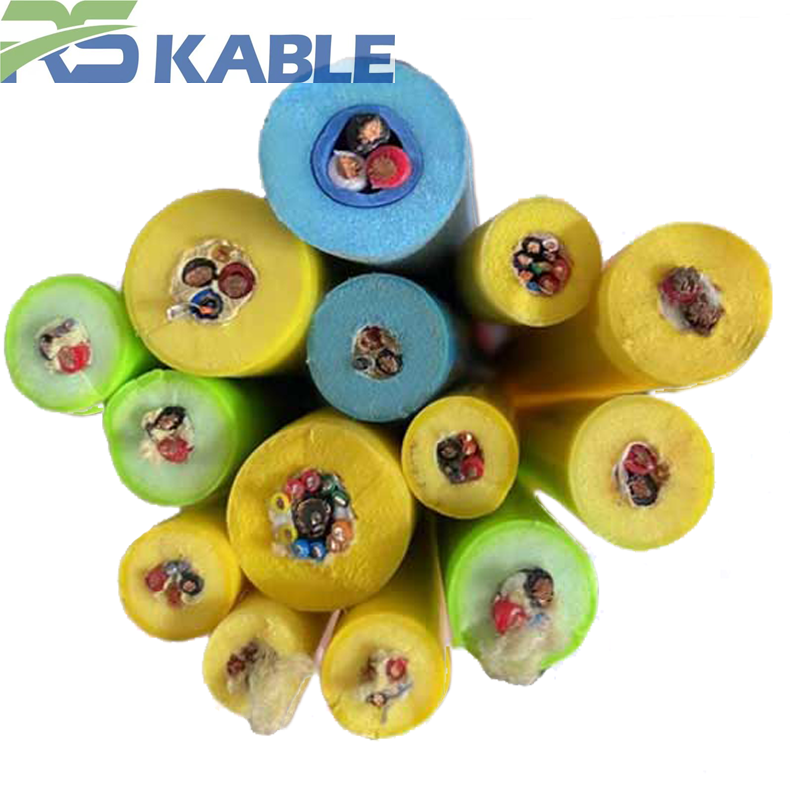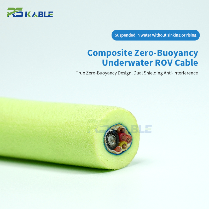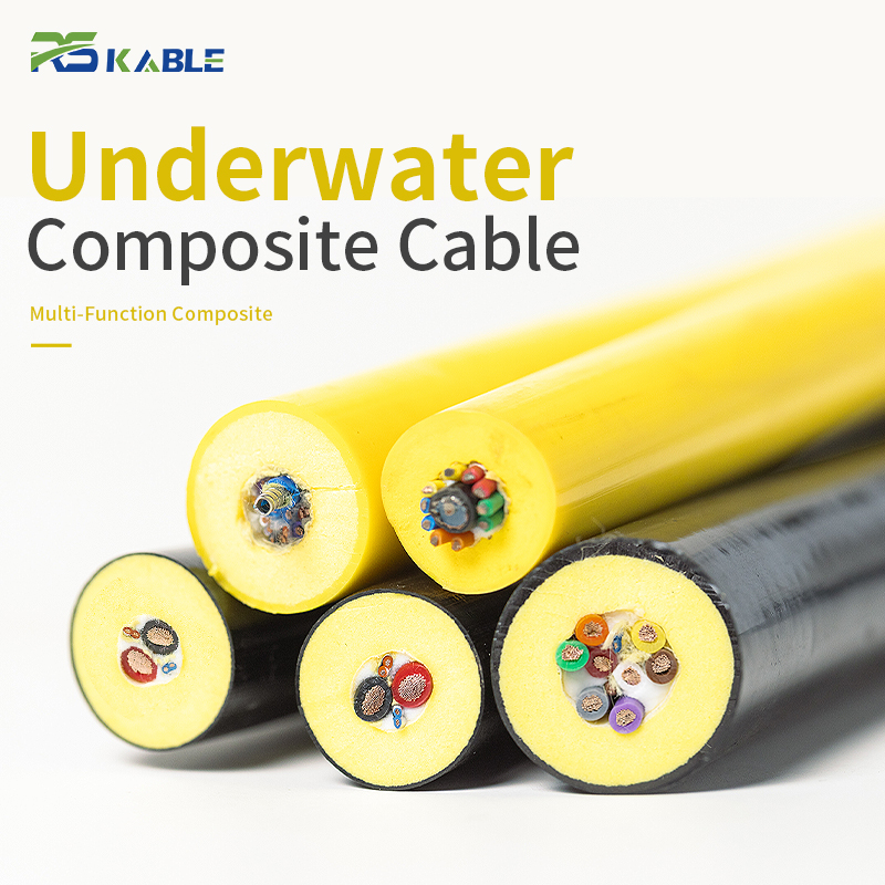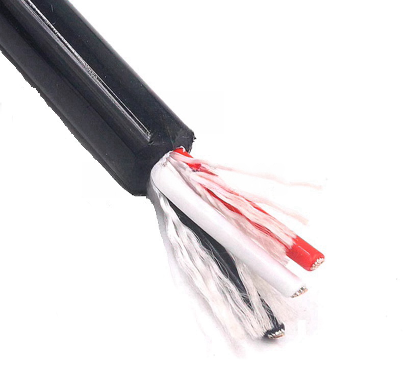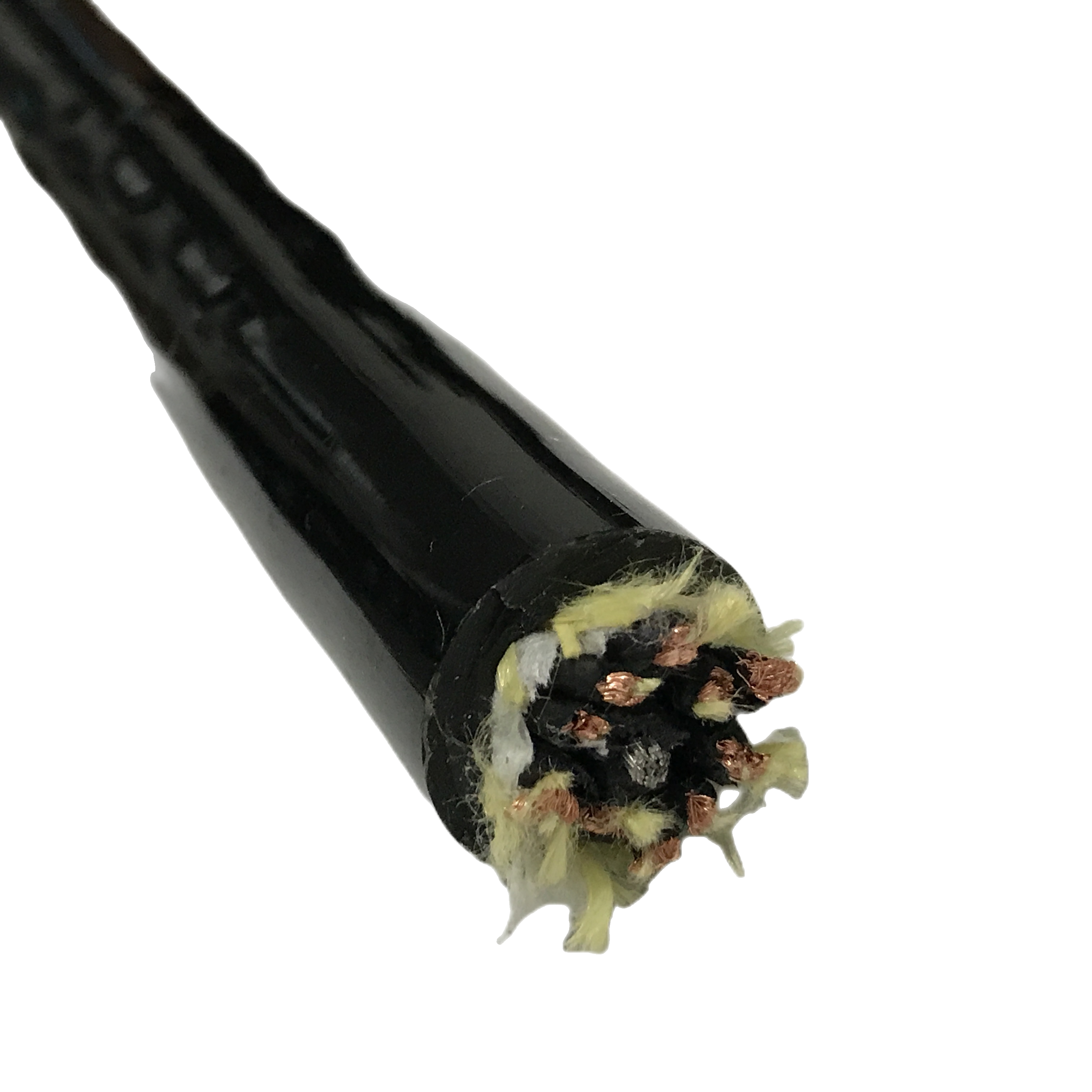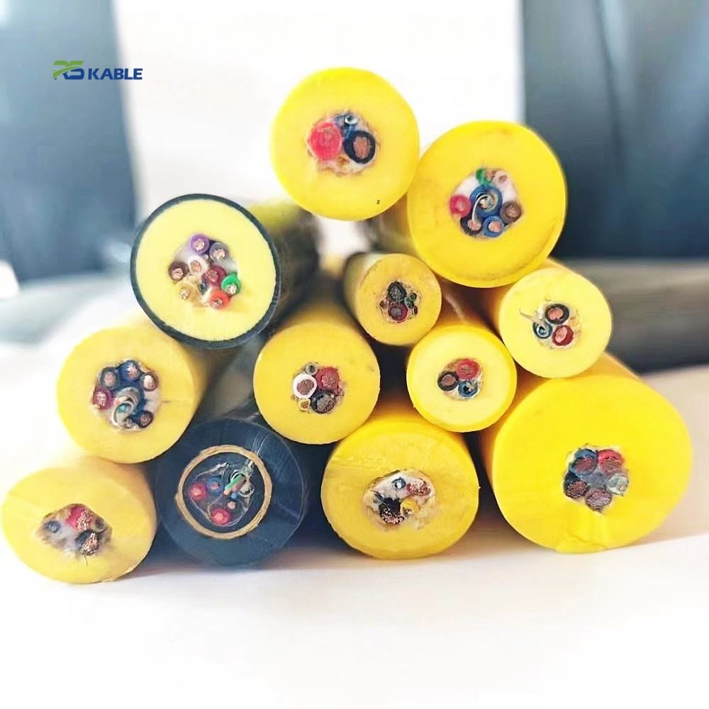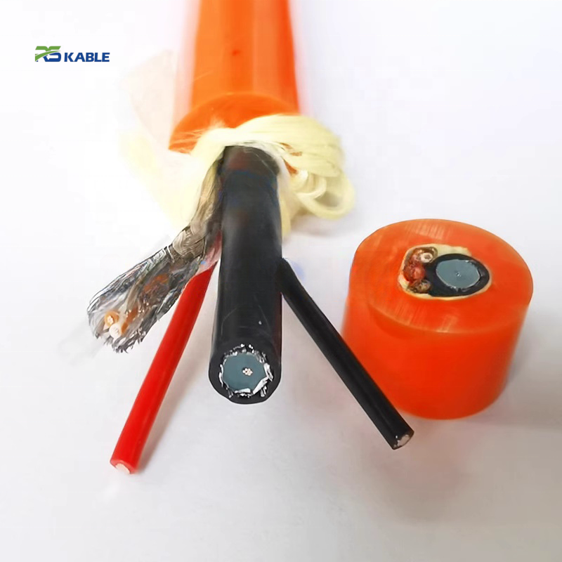
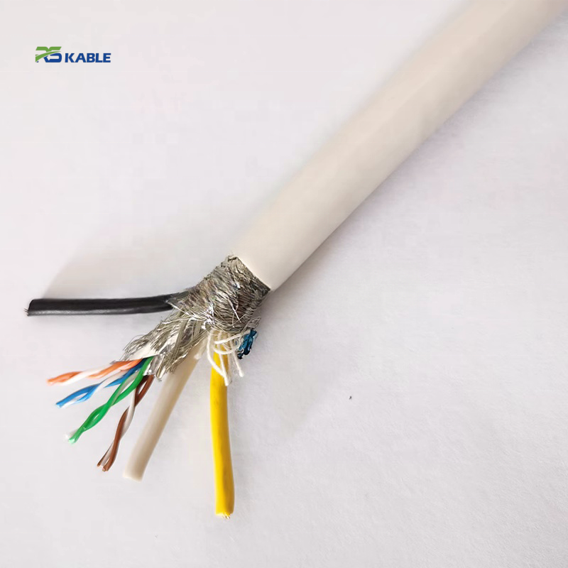
PUR Shielded Robot Cable for Automation with Low Noise and Anti-Interference Structure
The RST-SN series is a PUR shielded robot cable with dual anti-interference structure (AL/PET pair foil + Cu braid) providing TI < 22 mΩ/m and CMRR ≥ 65 dB — noise floor quantified for 4–20 mA, analogue, and digital automation signals.
Key Benefits:
✅ Noise floor < 0.8 mV at 50 mV/m field — 160× margin below ±0.5% accuracy threshold
✅ TI < 22 mΩ/m maintained through 5M flex cycles — measured at bend mid-point
✅ Class 6 conductors · Ether-type PUR 88 Shore A · −40 °C to +90 °C · CE · UL
✅ Free noise floor calculation sheet for your signal type and cable length on request
PUR Shielded Robot Cable for Automation with Low Noise and Anti-Interference Structure
A PUR shielded robot cable specification that only states ‘shielded’ without quantifying the induced noise amplitude at the signal receiver does not allow the system designer to verify that the cable is adequate for their signal accuracy requirement. A 4–20 mA current loop with a ±0.5% full-scale accuracy requirement cannot tolerate more than ±0.08 mA of noise (0.5% × 16 mA span). A 0–10 V analogue output with ±1% accuracy cannot tolerate more than ±100 mV. Whether a cable’s shielding is adequate depends on these numbers — not on whether the cable has a braid.
RST-SN is specified from the receiver perspective: transfer impedance, combined with the expected field strength at the cable installation location, gives a calculated induced noise voltage that can be directly compared against the signal accuracy budget. This page documents the noise floor calculation method, the TI performance data through 5M flex cycles, the product variants matched to specific signal types, and the anti-interference structure that makes the noise floor calculation predictable across the cable’s service life.
Difference from RST-ES (shielded robot cable for EMI/RFI): RST-ES is optimised for encoder and high-frequency digital signal applications with silver drain option for TI < 16 mΩ/m. RST-SN covers the full range of automation signal types — analogue 4–20 mA, 0–10 V, thermocouple, digital 24 V DC, and process fieldbus — with a noise floor calculation sheet provided for each application.
|
TI @ 1 MHz |
CMRR @ 1 MHz |
Noise floor |
Flex life |
|
< 22 mΩ/m |
≥ 65 dB |
< 0.8 mV |
≥ 5M cycles |
|
Measured at bend mid-point |
Common-mode rejection |
4–20 mA · 50 mV/m field |
TI maintained in spec |

Noise Floor Quantification: From Transfer Impedance to Signal Accuracy Budget
How to calculate the noise voltage induced in a PUR shielded robot cable
The induced noise voltage V_noise in a shielded cable is calculated as: V_noise = TI × I_interference × L, where TI is the transfer impedance (Ω/m), I_interference is the interference current on the cable outer surface (A), and L is the cable length (m).
In an automation workcell, the dominant interference source is the magnetic field from servo drive cables. For a servo cable carrying 10 A at 10 kHz switching frequency at 200 mm distance from the signal cable: the induced surface current on the shield is approximately I = H × 2πr where H is the magnetic field strength. At 200 mm from a 10 A conductor: H = I/(2πr) = 10/(2π × 0.2) = 7.96 A/m. The electric field equivalent at 10 kHz: E_equiv = H × Z_wave ≈ 50 mV/m. The surface current induced on a 1 m shield segment: I_surf ≈ E_equiv × L × shield_conductance ≈ 50 × 10^−3 × 1 × 0.05 = 2.5 mA.
With RST-SN TI = 22 mΩ/m and L = 10 m at 10 kHz: V_noise = 22 × 10^−3 × 2.5 × 10^−3 × 10 = 0.55 mV. On a 4–20 mA loop, this represents 0.55/16,000 = 0.0034% of span — 150× below the ±0.5% accuracy threshold. At 1 MHz (encoder signal frequency): surface current is higher by approximately 100× due to frequency scaling; V_noise = 22 × 10^−3 × 0.25 × 10^−3 × 10 = 55 mV — adequate for digital encoder signals (sensitivity threshold 200 mV) but confirm for < 0.5% analogue accuracy at 1 MHz.
Noise floor reference table: RST-SN induced voltage vs signal type accuracy threshold
|
Signal type |
Accuracy requirement |
Max tolerable noise |
RST-SN induced noise (10 m, 50 mV/m field) |
Margin |
|
4–20 mA analogue |
±0.5% FS |
±0.08 mA |
< 0.8 mV → 0.0005 mA |
160× margin — RST-SN easily sufficient |
|
0–10 V analogue output |
±1% FS |
±100 mV |
< 5.5 mV |
18× margin — RST-SN sufficient |
|
Thermocouple K-type (0–1000°C) |
±1°C = ±40 μV |
±40 μV |
< 0.8 mV |
0.05× — RST-SN insufficient alone; use Tier 3 (pair foil + braid) and verify ≤ 300 mm cable separation |
|
24 V DC digital I/O |
Binary — noise margin ±12 V |
±12,000 mV |
< 55 mV |
218× margin — any shielding sufficient |
|
PROFIBUS DP at 12 Mbit/s |
RS-485 noise margin ±200 mV |
±200 mV |
< 55 mV |
3.6× margin — RST-SN sufficient; verify both-ends shield grounding |
|
EtherCAT / 100BASE-TX |
Eye opening ≥ 175 mV |
< 45 mV reflected noise |
< 12 mV TI-induced at 1 MHz |
3.8× margin — confirm impedance maintained at 100 Ω ±10% |
Thermocouple note: the ±40 μV noise threshold for a K-type thermocouple is below the RST-SN noise floor of < 0.8 mV in a standard servo drive workcell. For thermocouple wiring in high-EMI environments, specify pair-level foil isolation (Tier 3 from RST-IA or RST-ES) and route the cable ≥ 500 mm from all servo drive power cables. The differential input of a thermocouple transmitter provides 60–80 dB CMRR, but this does not help for differentially-induced noise (NEXT or TI-coupled).
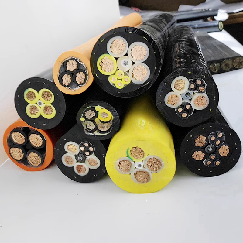
Anti-Interference Structure: Two Mechanisms, Two Frequency Ranges
How the RST-SN shielded robot cable achieves low noise across the automation signal frequency range
Electromagnetic interference in automation workcells spans four decades of frequency — from the 50 Hz power frequency ground loop at the low end to the 1–10 MHz range of encoder edge rates at the high end. No single shielding mechanism provides low transfer impedance across this entire range.
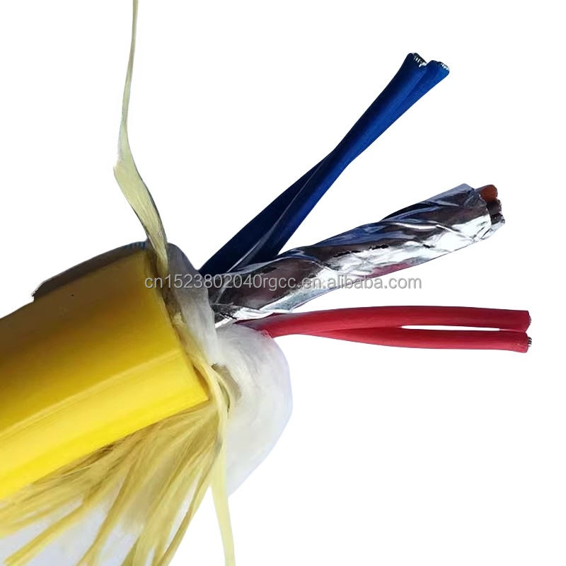
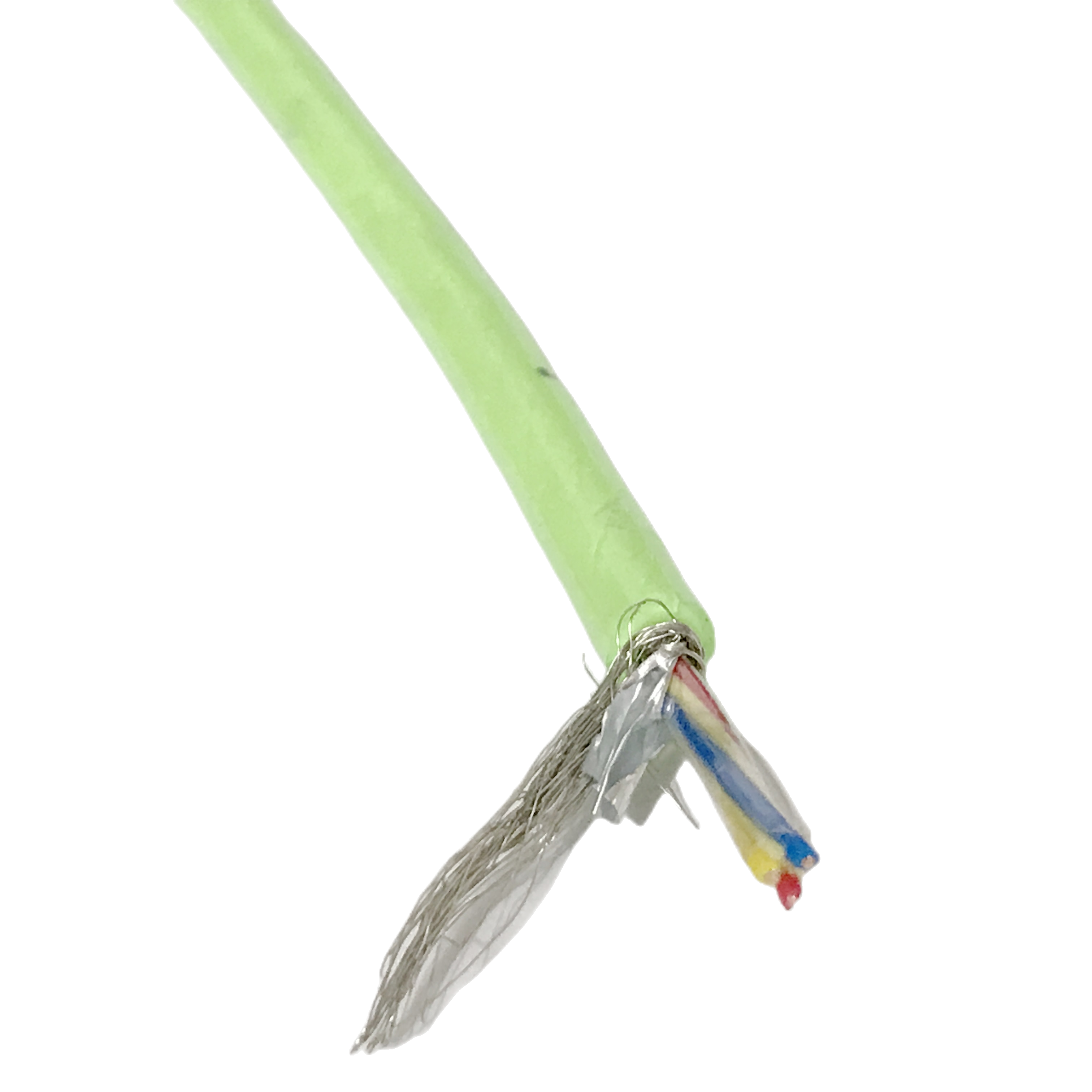
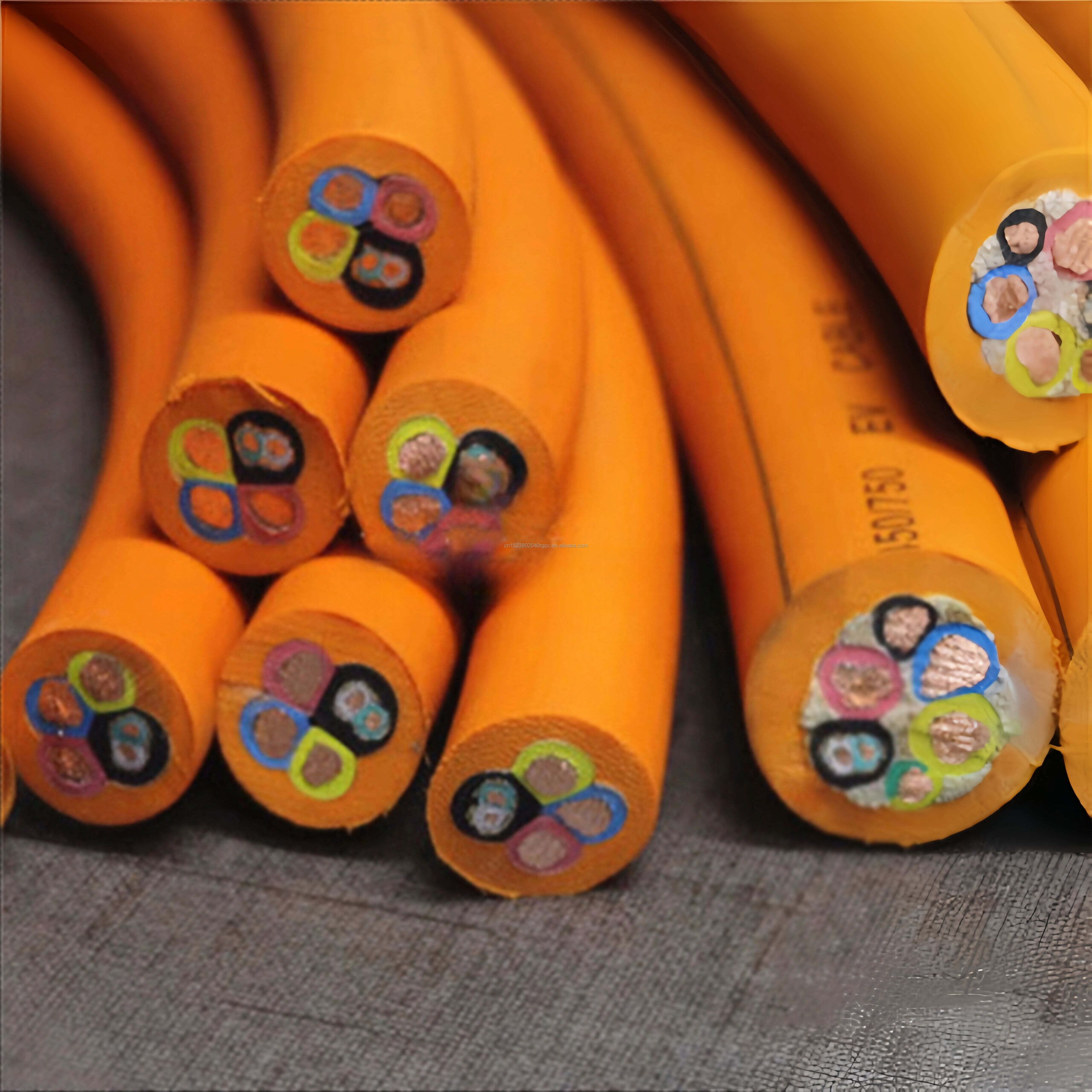
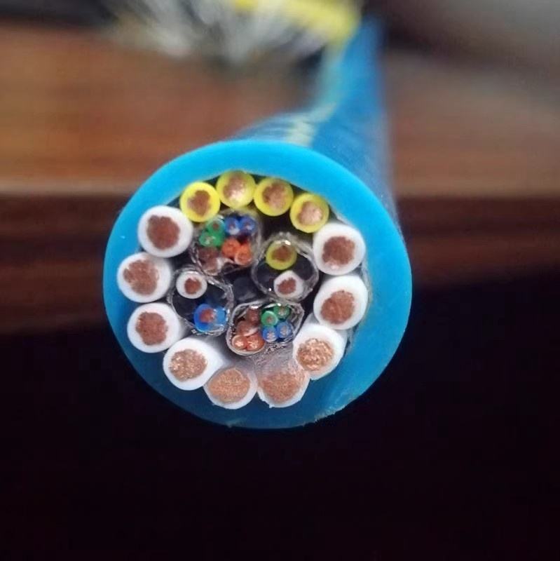
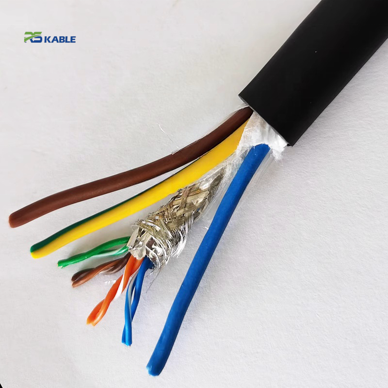
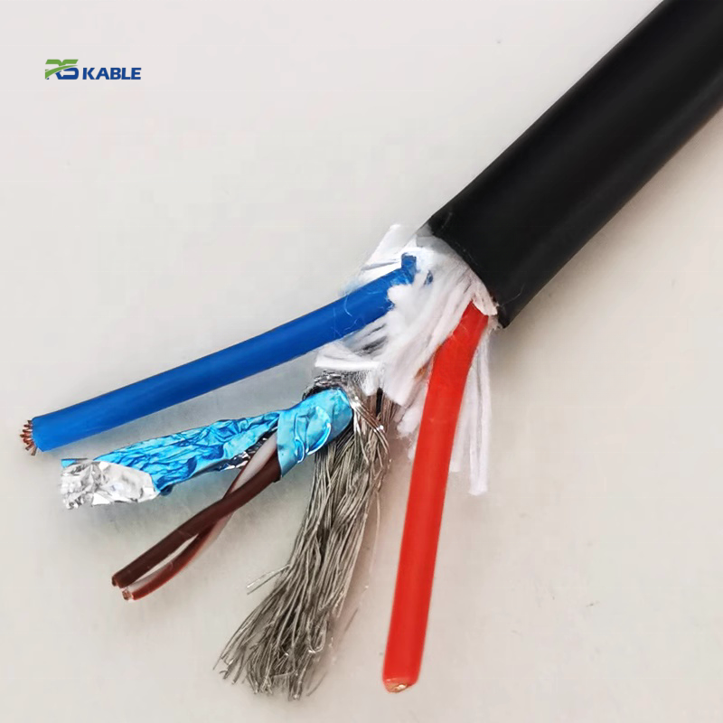
Mechanism 1 — AL/PET pair foil (pair-level, 100% coverage)
The aluminium foil acts as a Faraday cage around each individual pair. Its primary function is electric field shielding — at frequencies where capacitive coupling dominates (above approximately 100 kHz), the foil reduces inter-pair coupling by providing a low-impedance path for the displacement current. At 1 MHz, pair foil reduces inter-pair crosstalk by 12–15 dB compared to unfoiled cable. The foil is thin (approximately 0.05 mm Al + 0.012 mm PET backing) and has negligible mass contribution to cable stiffness — it does not significantly change the minimum bend radius.
Mechanism 2 — Tinned Cu overall braid (overall, ≥ 88% optical coverage)
The copper braid provides the primary low-frequency magnetic field shielding. At frequencies below 100 kHz, the braid’s low DC resistance (0.8–1.2 Ω/km) provides a low-impedance path for induced currents to flow — reducing the net magnetic flux inside the cable. The braid is most effective in the 1 kHz–1 MHz range. Above 1 MHz, braid inductance begins to increase TI — this is why the pair foil is also needed for encoder signal applications above 1 MHz.
RST-SN uses 32–38° braid weave angle — validated for ±180°/m robot arm torsion without wire-to-wire abrasion (> 42°) or coverage collapse (< 28°). Braid coverage at 5M flex-torsion cycles: ≥ 85%. TI at 5M cycles: < 28 mΩ/m at 1 MHz — within the < 30 mΩ/m service-life specification.
TI frequency profile: foil, braid, and combined — RST-SN vs braid-only cable
|
Frequency |
RST-SN foil+braid TI (initial) |
RST-SN foil+braid TI (5M cycles) |
Braid-only cable TI (initial) |
Braid-only cable TI (1M cycles) |
Dominant mechanism |
|
1 kHz |
6 mΩ/m |
8 mΩ/m |
9 mΩ/m |
11 mΩ/m |
Braid DC R |
|
10 kHz |
8 mΩ/m |
11 mΩ/m |
12 mΩ/m |
16 mΩ/m |
Braid R + foil |
|
100 kHz |
12 mΩ/m |
17 mΩ/m |
14 mΩ/m |
28 mΩ/m |
Braid inductance begins |
|
1 MHz |
22 mΩ/m |
28 mΩ/m |
38 mΩ/m |
95 mΩ/m |
Foil dominates at 1 MHz |
|
10 MHz |
48 mΩ/m |
62 mΩ/m |
290 mΩ/m |
> 500 mΩ/m |
Foil only effective |

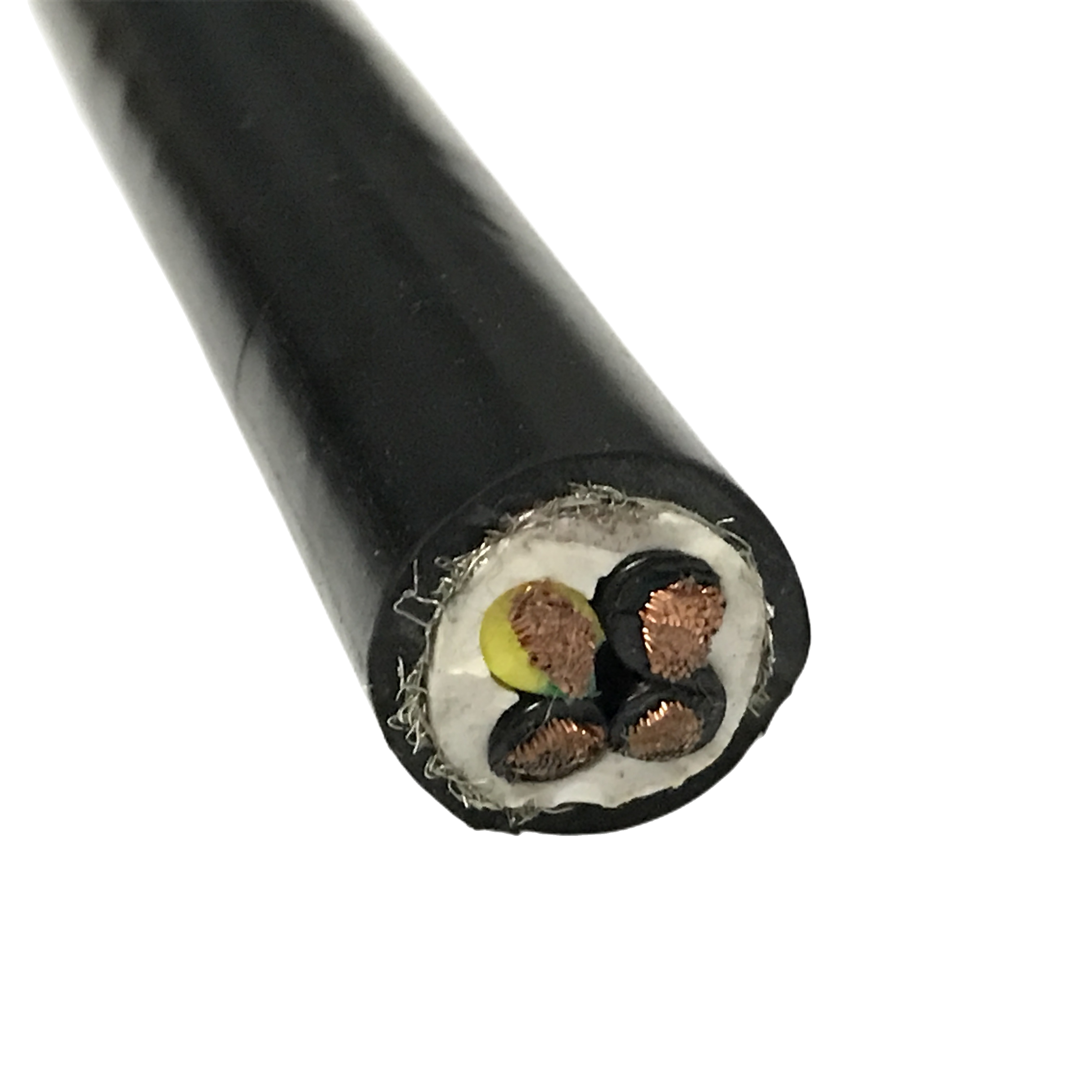
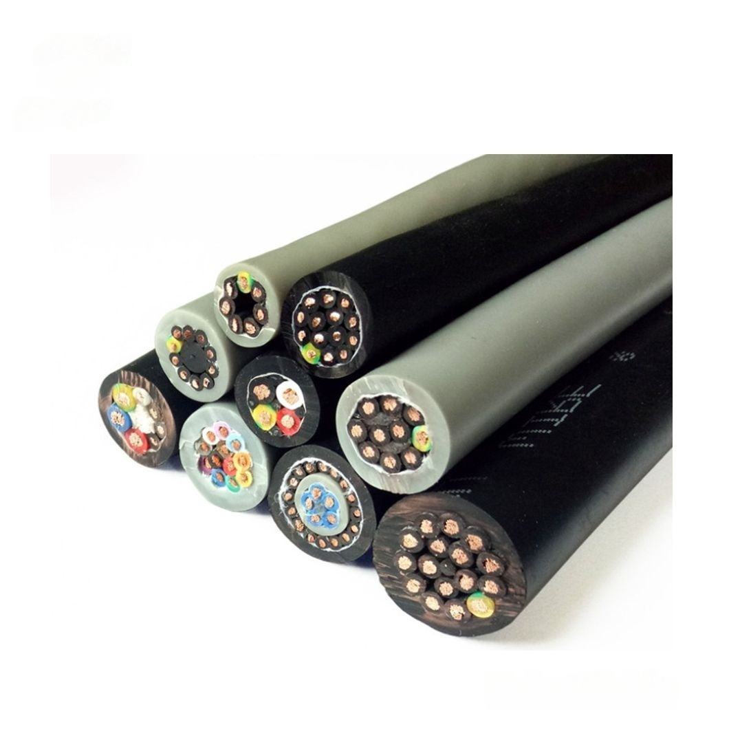
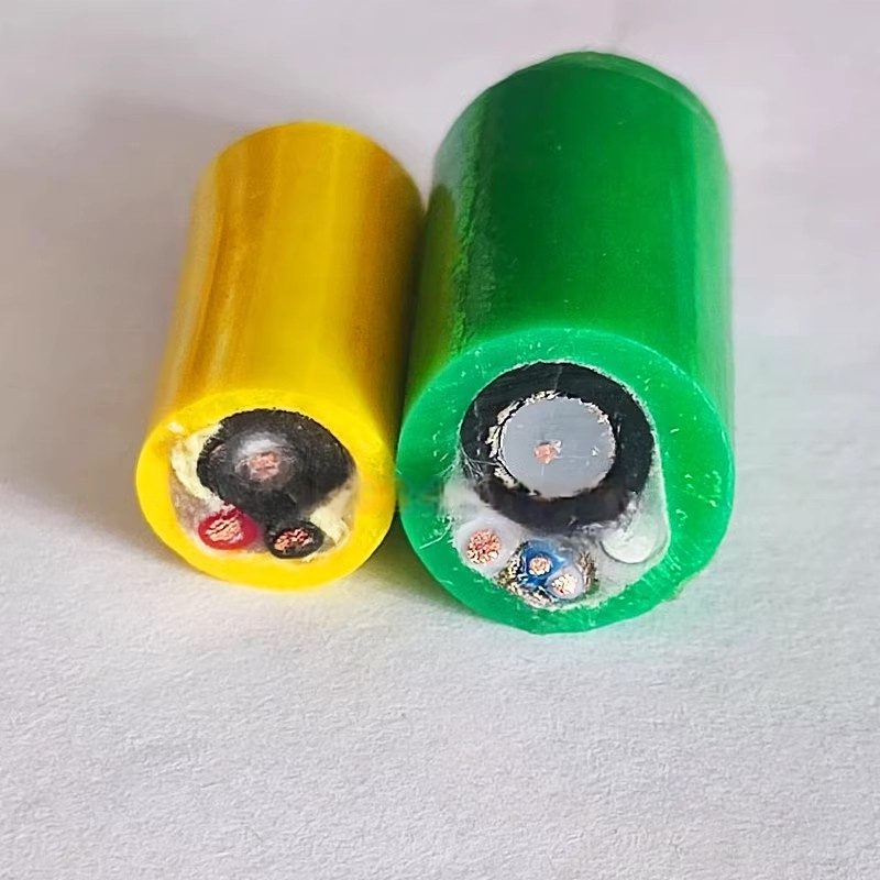
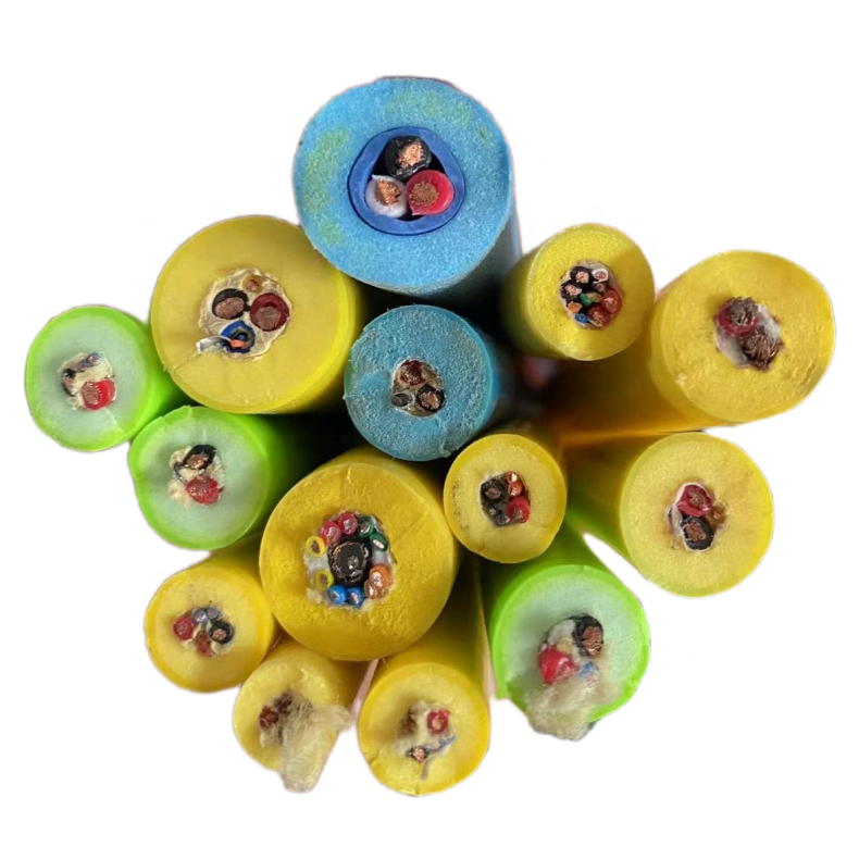
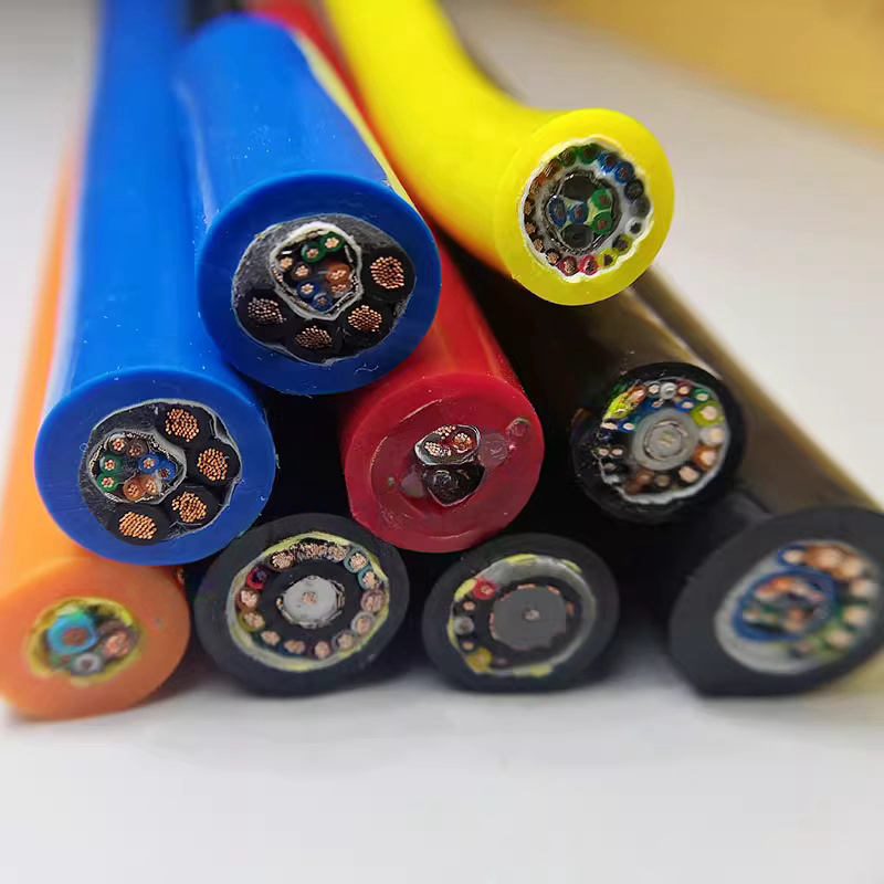
RST-SN Series Product Matrix
PUR shielded robot cable — noise-optimised configurations by signal type
All RST-SN: Class 6 conductors, AL/PET pair foil (100%) + Cu braid (≥ 88%), ether-type PUR 88 Shore A, ≥ 5M flex cycles. TI measured at 4× OD bend mid-point.
|
Model |
Cores/pairs |
Shield |
Flex life |
OD (mm) |
TI@1MHz |
Min bend R |
Signal type |
|
RST-SN-110 |
4×0.34 mm² |
Foil/pr+braid |
≥5M |
7.5±0.3 |
<22 mΩ/m |
5×OD=38mm |
4–20 mA · 0–10 V analogue |
|
RST-SN-120 |
4×0.75 mm² |
Foil/pr+braid |
≥5M |
9.0±0.3 |
<22 mΩ/m |
5×OD=45mm |
Servo env. control signal |
|
RST-SN-130 |
7×0.75 mm² |
Foil/pr+braid |
≥5M |
12.0±0.4 |
<22 mΩ/m |
5×OD=60mm |
Multi-core shielded I/O |
|
RST-SN-210 |
2pr×0.34 mm² |
Foil/pr+braid |
≥5M |
8.2±0.3 |
<22 mΩ/m |
5×OD=41mm |
Differential analogue · thermocouple pair |
|
RST-SN-220 |
4pr×0.34 mm² |
Foil/pr+braid |
≥5M |
12.5±0.4 |
<22 mΩ/m |
5×OD=63mm |
Multi-pair analogue bundle |
|
RST-SN-310 |
4×0.75 mm² |
Cu braid only |
≥5M |
8.5±0.3 |
<35 mΩ/m |
5×OD=43mm |
24 V DC digital I/O (braid only adequate) |
|
RST-SN-320 |
12×0.75 mm² |
Cu braid only |
≥5M |
13.5±0.4 |
<35 mΩ/m |
5×OD=68mm |
Full 24 V DC I/O bundle |
|
RST-SN-410 |
3×1.5+4×0.75 |
Signal foil+braid |
≥3M |
14.5±0.5 |
<25 mΩ/m |
5×OD=73mm |
Servo power + shielded ctrl |
|
RST-SN-C (ETO) |
Per spec |
Per spec |
Per design |
4–22 mm |
Per spec |
Per OD |
LSZH · torsion · custom |
RST-SN-310/320 (braid only, TI < 35 mΩ/m): for 24 V DC digital signals where the ±12 V noise margin provides 218× headroom above the RST-SN noise floor at standard field strength. Pair foil is not required for digital I/O and reduces cable OD. For analogue signals (4–20 mA, 0–10 V, thermocouple), always specify foil+braid models (RST-SN-110 to RST-SN-220).
Technical Specification
PUR shielded robot cable conductors, shielding, and mechanical parameters
|
Parameter |
Specification |
|
Conductor |
IEC 60228 Class 6; 0.34 mm²: ≥130 wires; 0.75 mm²: ≥196 wires; wire ≤ 0.10 mm; helical lay 15–20× OD |
|
DC resistance @ 20°C |
0.34 mm²: ≤56.0 Ω/km · 0.75 mm²: ≤25.5 Ω/km · 1.5 mm²: ≤13.7 Ω/km |
|
Pair shield |
AL/PET foil 100% coverage; drain wire 0.5 mm² OFC bonded at 60 mm intervals (prevents torsion-induced drain abrasion at robot wrist joints) |
|
Overall braid |
Tinned Cu; coverage ≥ 88% initial; ≥ 85% at 5M cycles; weave angle 32–38° — validated for ±180°/m robot arm torsion |
|
TI — foil+braid |
< 22 mΩ/m initial; < 28 mΩ/m at 5M cycles. Measured at 4× OD bend mid-point per IEC 62153-4-3 — not static straight cable |
|
CMRR @ 1 MHz |
≥ 65 dB — common-mode rejection ratio; limits ground-loop and common-mode noise from reaching signal conductors |
|
Shielding effectiveness |
≥ 55 dB @ 1 MHz; ≥ 45 dB @ 10 MHz per IEC 62153-4-6 |
|
Outer jacket |
Ether-type PUR 88 Shore A; −40°C to +90°C; IEC 60811 Group 1 oil resistance; cold flex −40°C no cracking at 5× OD |
|
Flex life |
≥ 5M cycles signal/control (5× OD); ≥ 3M cycles power (RST-SN-410). Criterion: TI < 30 mΩ/m + R change < 2% + no conductor open |
|
Min bend radius |
5× OD dynamic (all shielded models); 3× OD static installation |
|
Rated voltage |
Signal/control: 300/500 V AC. Power (RST-SN-410): 450/750 V AC |
Grounding Rules and Field Diagnostics
Correct shield grounding for low-noise analogue and digital signal cables
The noise floor calculation assumes correct single-end grounding for analogue signal cables. Both-ends grounding on analogue cables creates a ground loop whose current adds directly to the signal noise, defeating the shield. For data cables (RS-485, Ethernet), both-ends PE grounding is correct — differential receivers reject common-mode noise at 60–80 dB CMRR.
|
Signal |
Controller end |
Sensor / field end |
Note |
|
4–20 mA · 0–10 V analogue |
Shield to PE rail |
Float |
Single-end mandatory — both-ends creates 50 Hz ground loop that adds directly to mA-level signal |
|
Thermocouple / PT100 |
Shield to PE at transmitter |
Float at sensor |
Keep ≥ 500 mm from servo power cables — even with RST-SN shielding, thermocouple μV signal level requires maximum physical separation |
|
24 V DC digital I/O |
Shield to PE at PLC |
Float at sensor |
Single-end preferred; both-ends acceptable for digital given ±12 V noise margin |
|
PROFIBUS / RS-485 |
Both ends to PE |
Both ends to PE |
Both-ends required per IEC 61784-5-3; differential receiver CMRR rejects ground loop noise |
Three field diagnostics using the noise floor model
|
Symptom |
Most likely cause |
Confirming test |
Correction |
|
Analogue signal noise fixed amplitude, not correlated with motor speed |
50 Hz ground loop — both-ends shield grounding |
Disconnect shield at sensor end. If noise drops > 20 dB: ground loop confirmed |
Float shield at sensor end. Verify shield is on PE rail at controller end — not on 0 V signal reference. Ground loop adds to signal directly; shielding upgrade will not fix a grounding error. |
|
Analogue noise increases with motor load and speed |
TI too high — shield degraded or inadequate |
Measure TI at cable bend mid-point with LCR bridge at 10 kHz. Compare to initial value. |
If TI > 50 mΩ/m at 10 kHz: braid degraded. Replace with RST-SN (foil+braid, TI < 22 mΩ/m). Verify ≥ 200 mm separation from servo power cable and single-end grounding first — these are more common causes than cable degradation. |
|
Digital I/O false triggers at specific axis positions |
Inductive coupling from servo cable at axis position — not TI issue |
Move servo power cable 150 mm further from I/O cable. If fault disappears: magnetic coupling, not TI |
Separate servo power and I/O cables by ≥ 150 mm or add grounded metal divider. Shielded cable attenuates electric field coupling but not magnetic coupling at close range — separation is the correct fix for magnetic coupling at robot joints. |
Frequently Asked Questions
How do I know if RST-SN PUR shielded robot cable is adequate for my signal accuracy requirement?
Use the noise floor calculation: V_noise = TI × I_surf × L. For a 10 m cable at 50 mV/m field strength: I_surf ≈ 2.5 mA (at 10 kHz). V_noise = 22 × 10^−3 × 2.5 × 10^−3 × 10 = 0.55 mV. Compare to your noise tolerance: 4–20 mA at ±0.5% = ±80 μA tolerance (0.08 mA). Convert 0.55 mV to mA for a 250 Ω loop: 0.55/250 = 0.0022 mA — 36× below the 0.08 mA tolerance. RST-SN is sufficient. For thermocouple (40 μV tolerance): 0.55 mV > 40 μV — RST-SN alone is not sufficient; upgrade to pair foil with ≥ 500 mm cable separation.
Why is ether-type PUR specified and not ester-type for this shielded robot cable?
Ether-type PUR has no ester linkages, which eliminates the autocatalytic hydrolysis mechanism that degrades ester-type PUR in humid and wet environments. In a robot arm with occasional condensation or coolant mist, ester-type PUR develops cracks within 18–30 months as the acid produced by hydrolysis catalyses further chain scission. Ether-type PUR maintains its tensile strength and elasticity in humid environments indefinitely. The compound type is not identifiable visually — request written confirmation of PUR chemistry type when comparing supplier quotations for shielded robot cable.
Can RST-SN be used in drag chain and robot arm installations interchangeably?
Yes. All RST-SN models are designed for both applications. The relevant constraints are: drag chain requires minimum inner radius ≥ 5× cable OD; robot arm requires free cable length ≥ (joint rotation ÷ 180) × 1.20 m for torsion compliance, plus 5× OD minimum bend radius at each joint. For robot wrist joints (J4/J5) with compound flex-torsion loading, apply the 0.40× life correction factor (from the RST-IA series documentation) to the rated 5M cycles — effective wrist life approximately 2M cycles at typical industrial robot cycle rates.
Request Samples, Noise Floor Calculation, or a Quotation
Specifying RST-SN PUR shielded robot cable for your automation signal requirements
Rousheng provides a free noise floor calculation for your specific signal type, cable length, and estimated field strength before order placement. For a complete first-reply response, include:
- Signal type: 4–20 mA, 0–10 V, thermocouple, 24 V DC digital, PROFIBUS, EtherCAT, or combined
- Signal accuracy requirement (% full scale) — for noise budget comparison
- Cable length (m) and distance from nearest servo drive or VFD power cable
- Application: robot arm wiring (joint), drag chain, or static installation
- Core count and cross-section; shielded foil+braid or braid-only
- Environment: standard industrial, oil/coolant, or outdoor
- Quantity in metres or assembled sets with connector types
|
CONTACT |
Email: Jerry@rstlkable.com WhatsApp / Phone: +86 134 8219 7396 Address: No. 2591 Fengzhe Road, Fengxian District, Shanghai, China |