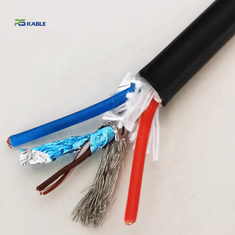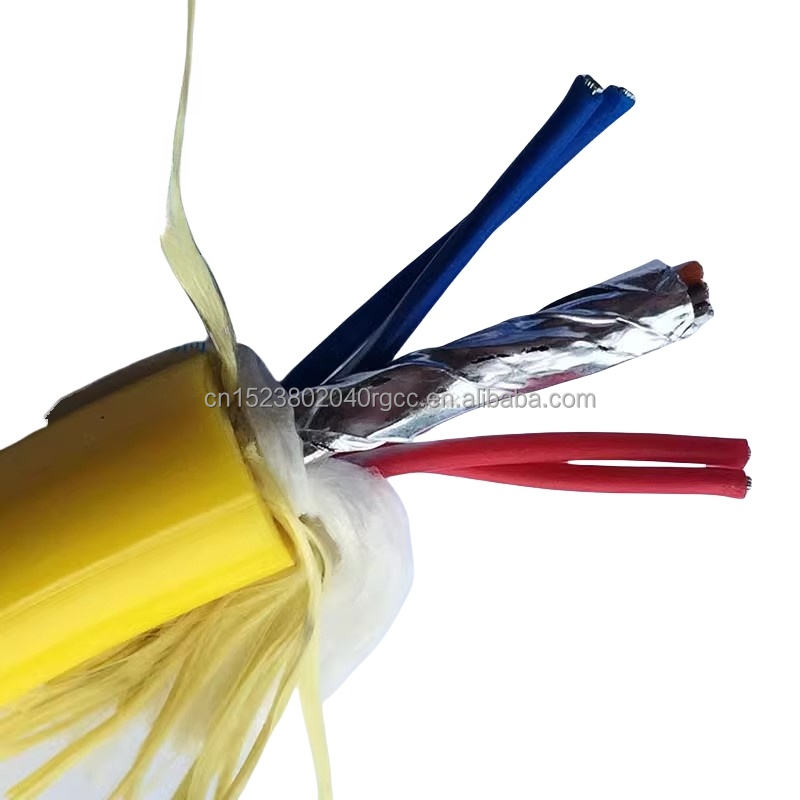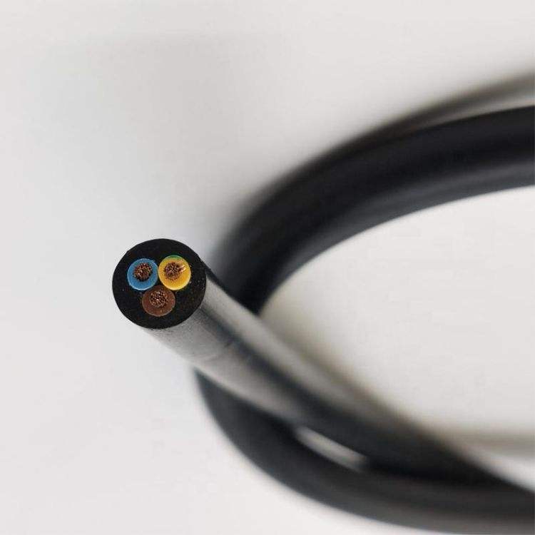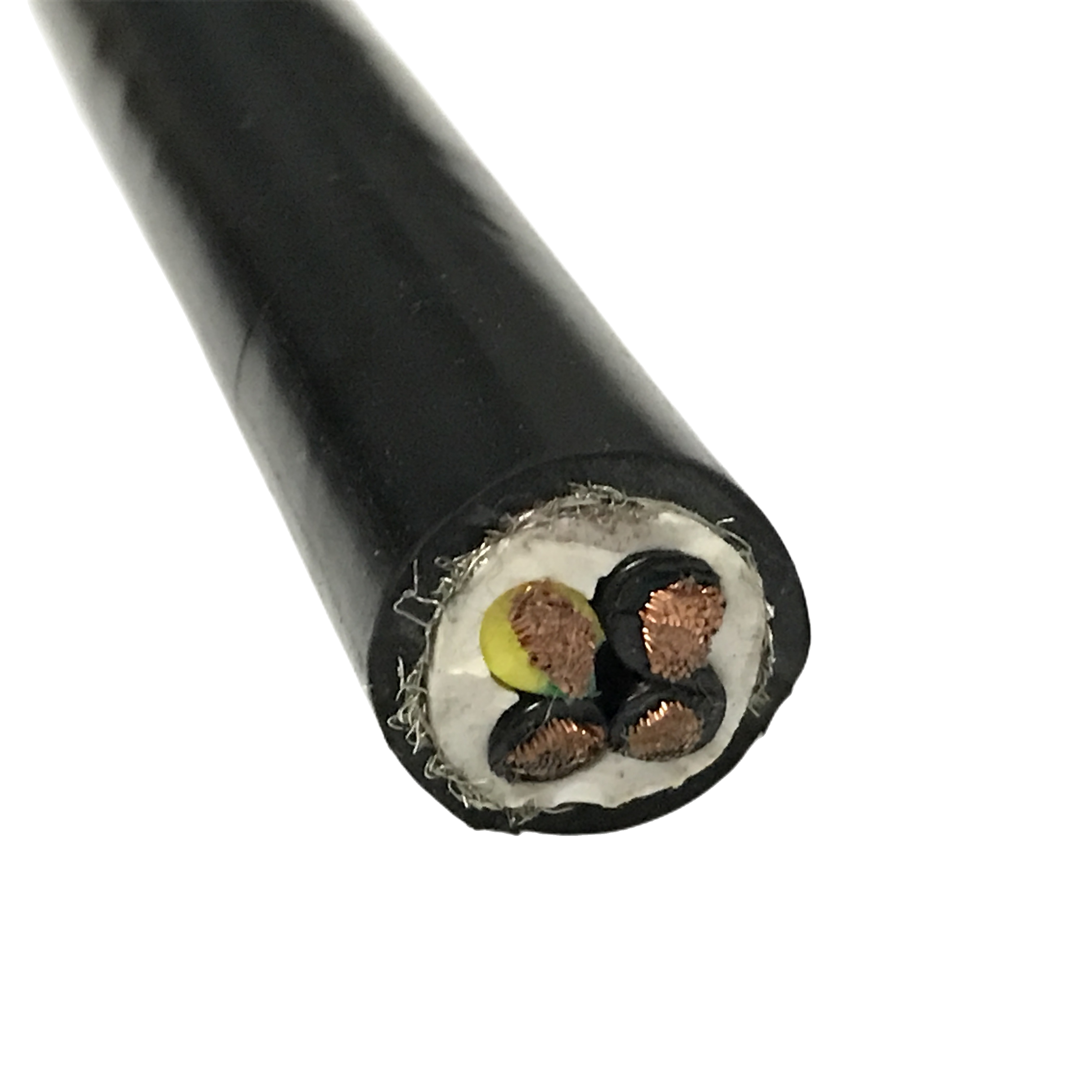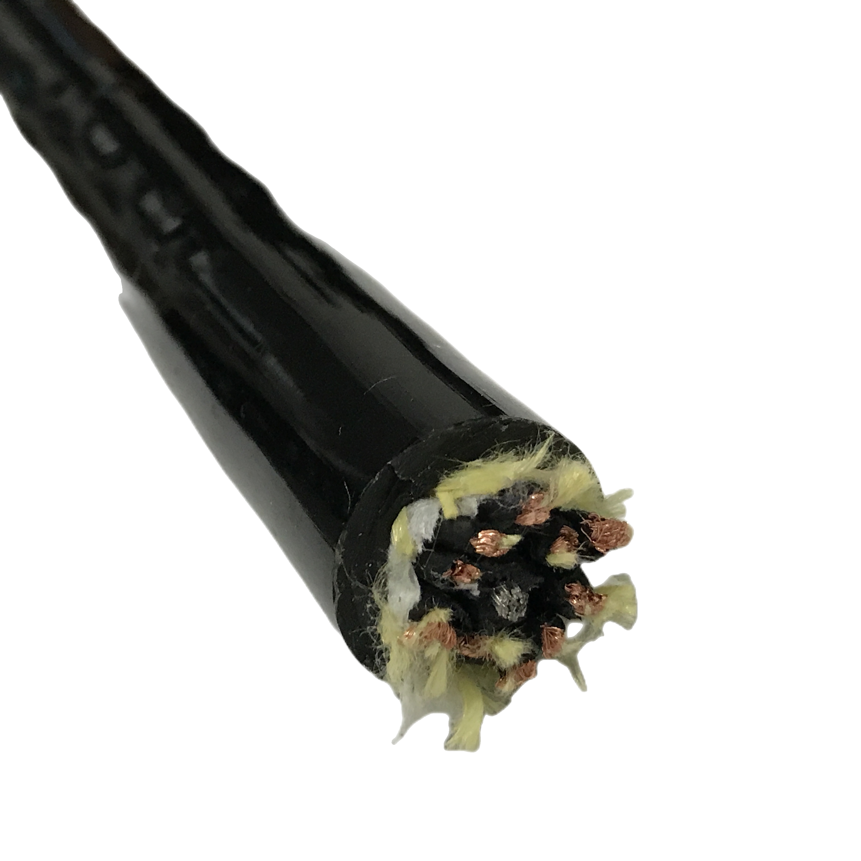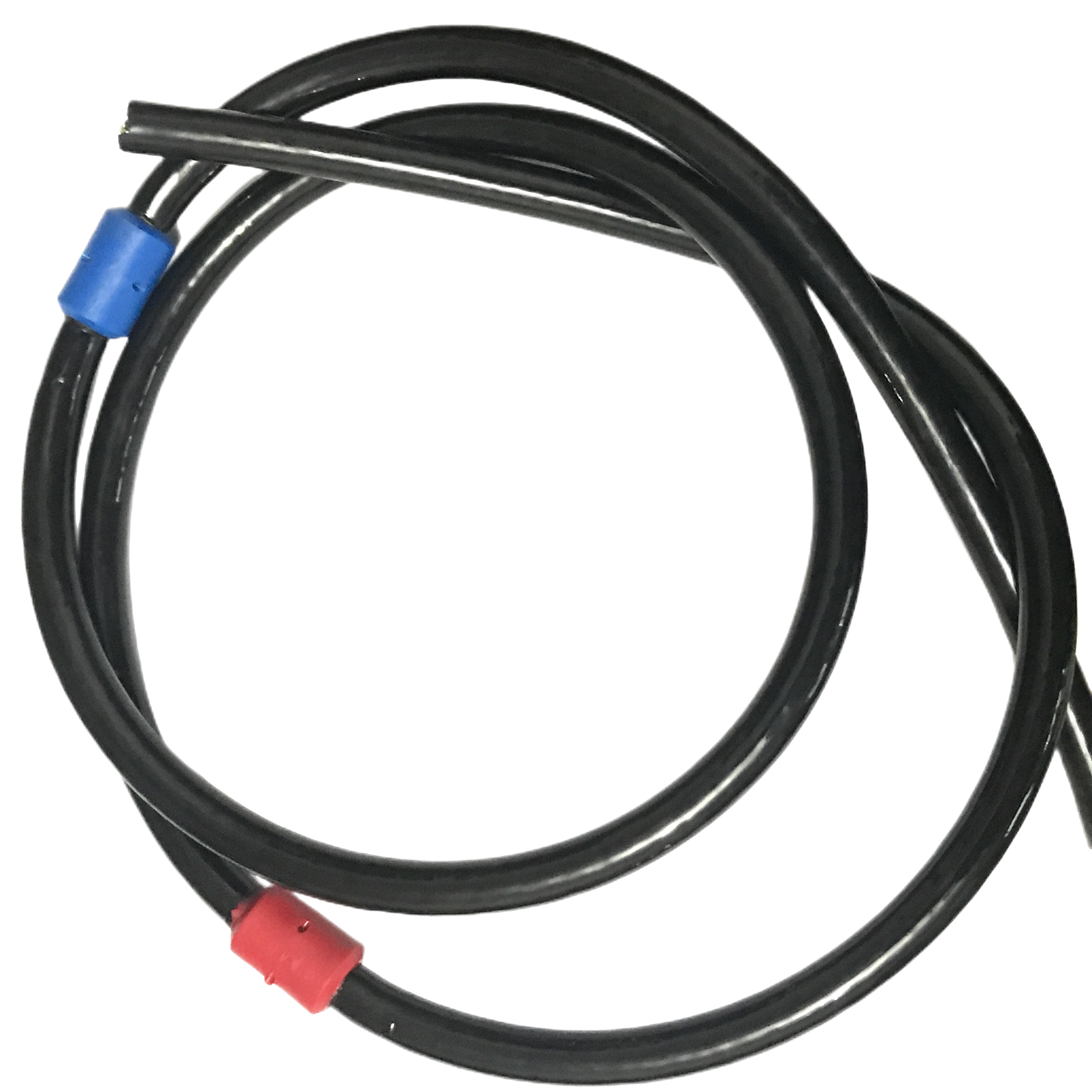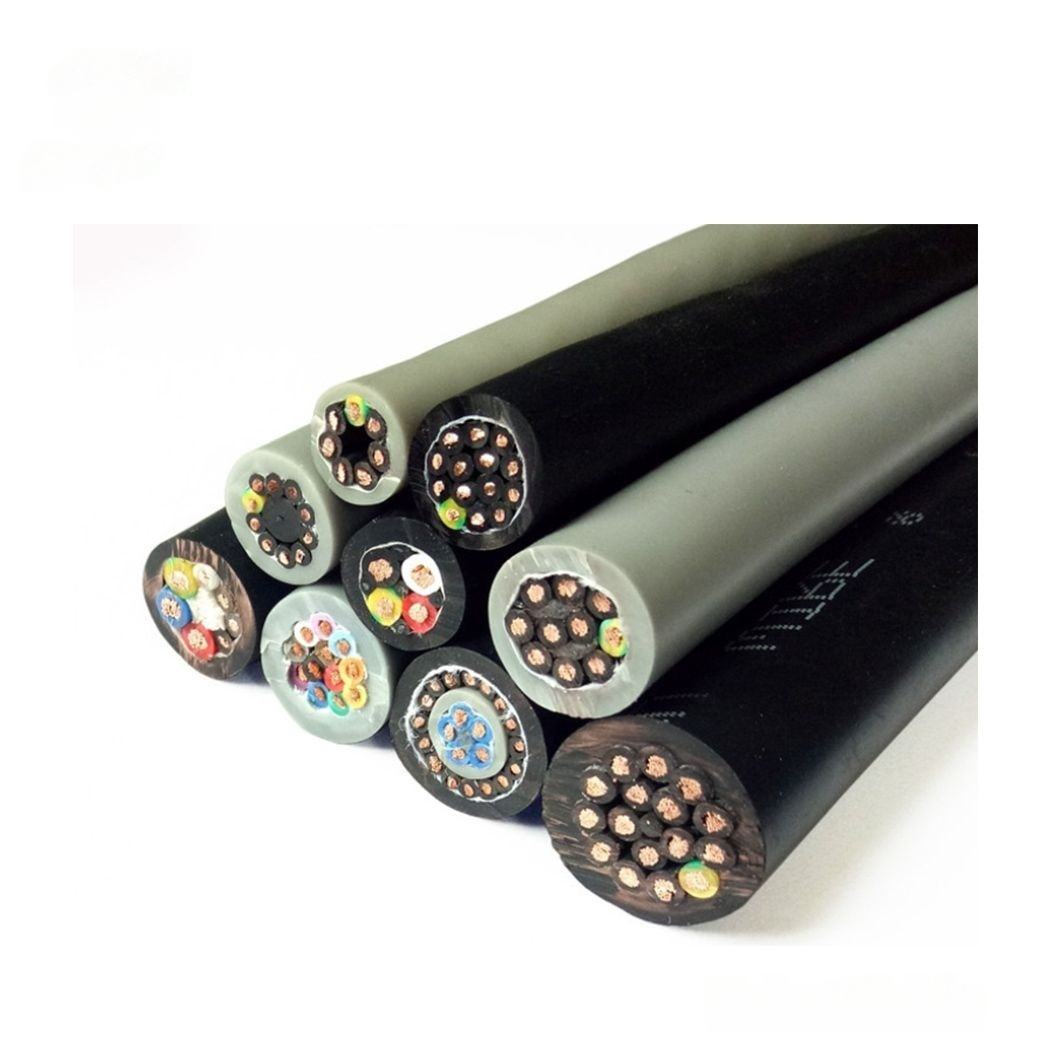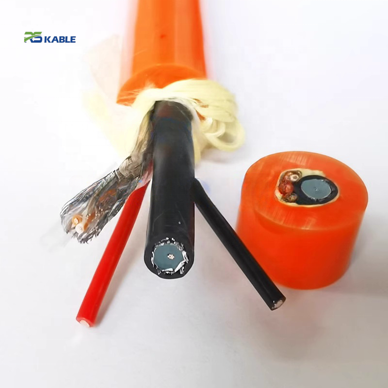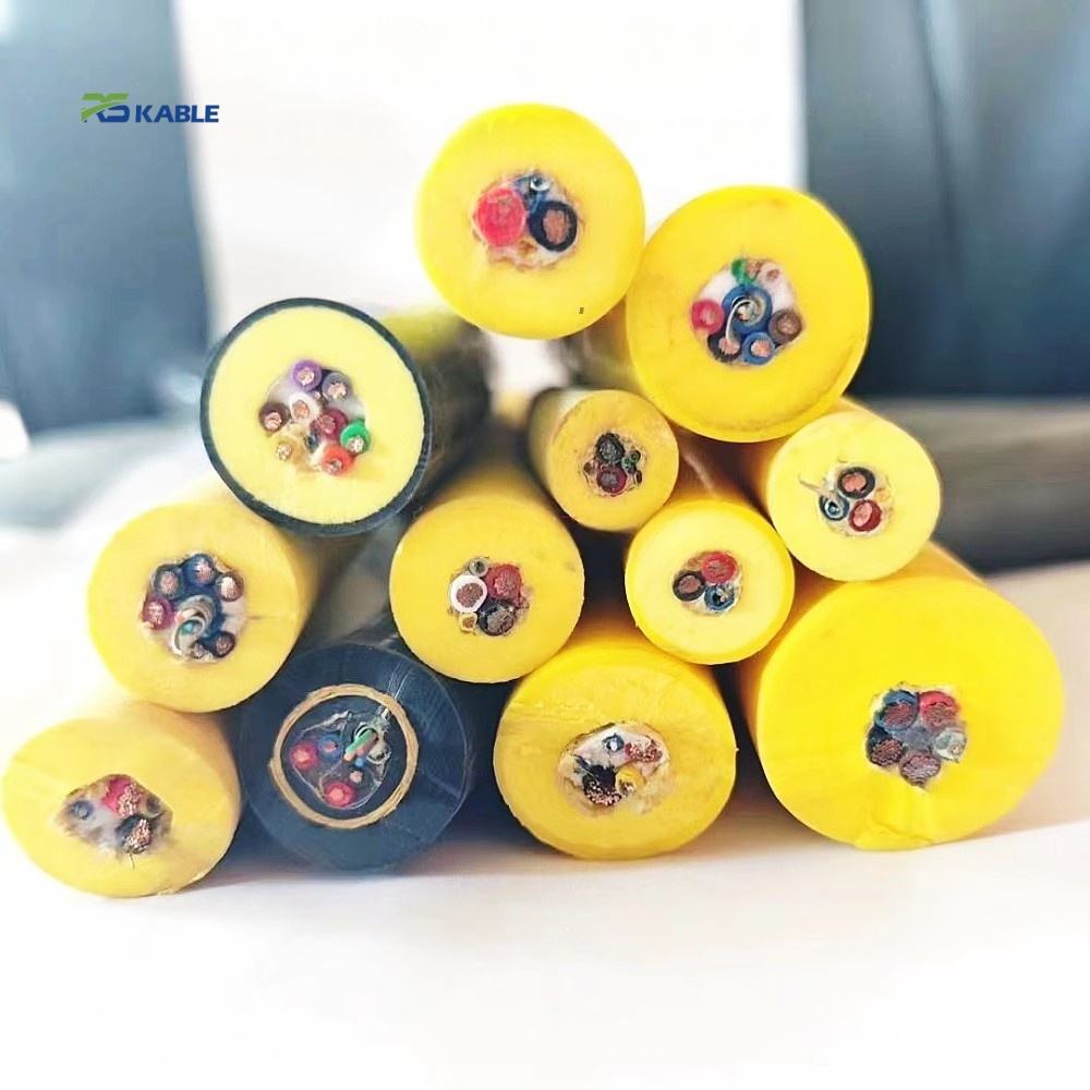
PUR Robot Cable for Continuous Motion Applications with Wear Resistant Jacket
The RST-WR series is a 92 Shore A thick-wall PUR robot cable (2.0–3.5 mm) designed for high-cycle drag chains and cable carriers. Its 10M flex cycle rating is conductor-limited, not jacket-limited, ensuring long-lasting performance in demanding industrial robotics.
Key Benefits:
✅ ≥10M flex cycles – jacket wear <10% at limit (133× safety margin)
✅ 92 Shore A PUR – Taber 11 mg/1k cycles → 0.015 mm depth loss
✅ Speed correction 0.7× above 5 m/s (wear ∝ v^1.5)
✅ Class 6 conductors · −40 °C to +90 °C · CE · UL · Shielded & power variants
PUR Robot Cable for Continuous Motion Applications with Wear Resistant Jacket
Most PUR robot cable datasheets state a Shore A hardness and a Taber abrasion number without connecting them to a service life prediction. A cable rated at 90 Shore A and 20 mg/1,000 Taber cycles is obviously less wear-resistant than 92 Shore A at 11 mg/1,000 cycles — but neither number alone tells you how long the jacket lasts in your drag chain. RST-WR is designed from a calculated wear budget: Taber rate → volume loss per cycle → depth loss per cycle → wall thickness ÷ depth rate = cycles to wall exhaustion. The calculation shows the 10M cycle rating is set by conductor fatigue, not by jacket wear.
This page documents the wear budget derivation, the Hertz-contact-derived speed correction factor, the three-series selection framework for dry versus wet versus chemically aggressive environments, and the drag chain installation parameters that most affect actual wear rate.
|
Flex life |
Jacket hardness |
Taber rate |
Wall at 10M cyc |
|
≥ 10,000,000 |
92 Shore A |
11 mg / 1k cyc |
< 10% consumed |
|
4× OD · conductor-limited |
Ether-type PUR |
→ 0.015 mm depth / 1k cyc |
Wear not the limiting factor |

The Wear Budget Calculation: From Taber Test to Service Life Prediction
Step-by-step PUR robot cable jacket wear rate derivation — RST-WR-220 reference
The Taber abrasion test (ASTM D1044, CS-10 wheel, 500 g load) produces weight loss in mg per 1,000 cycles. Converting this to a depth loss requires the jacket compound density and the contact geometry. The following calculation uses RST-WR-220 (9.5 mm OD, 2.0 mm outer jacket wall, density 1.22 g/cm³).
|
Taber weight loss |
11 mg per 1,000 abrasion cycles (CS-10 wheel, 500 g load, ASTM D1044) |
|
Volume loss |
11 mg ÷ 1,220 mg/cm³ (PUR 92A density) = 0.00902 cm³ per 1,000 cycles |
|
CS-10 contact area |
CS-10 wheel contact footprint ≈ 6.0 cm² (wheel width 12.7 mm × contact arc 47 mm) |
|
Depth loss per 1,000 cycles |
0.00902 cm³ ÷ 0.60 cm² = 0.0150 mm per 1,000 cycles under Taber conditions |
|
Wall at rated 10M cycles |
0.0150 mm/1,000 cyc × 10,000 = 0.150 mm consumed — 7.5% of 2.0 mm wall |
|
Theoretical wall exhaustion |
2.0 mm ÷ 0.0150 mm per 1,000 = 133,333 thousand cycles = 133M cycles (Taber conditions) |
|
Rated life vs wall limit |
10M cycles is 7.5% of the Taber-condition wear limit → 10M life set by conductor fatigue, not jacket wear |
Why actual drag chain wear rate is 15–30× lower than Taber: the contact mechanics derivation
The Taber number is measured under conditions that are more aggressive than a drag chain installation in three independent ways. Quantifying each factor shows why the 5–15× estimate in V1 was conservative — the actual ratio is closer to 15–30×.
|
Factor |
Taber test condition |
Drag chain condition |
Ratio (Taber ÷ drag chain) |
|
Normal contact force |
4.9 N (500 g × g) continuous |
0.5–1.5 N (cable weight + bending spring force component) |
3.3–9.8× higher in Taber. Midpoint: ~5.5× higher contact force |
|
Contact duty cycle |
100% continuous contact throughout test |
10–20% of each flex cycle in contact with chain inner surface (cable clears surface during mid-stroke) |
5–10× higher duty cycle in Taber |
|
Relative velocity |
Fixed 60 RPM wheel: surface speed ~450 mm/s at contact |
Varies with traverse speed; at 3 m/s traverse: chain inner contact ~150–300 mm/s |
1.5–3× higher relative velocity in Taber at typical drag chain speeds |
|
Combined ratio |
|
|
5.5 × 7.5 × 2 = 82× (upper estimate) to 3.3 × 5 × 1.5 = 25× (lower). Practical midpoint: 15–30× lower in drag chain than Taber. Conservative design uses 10× as safety margin. |
At the conservative 10× safety factor: effective depth loss in drag chain service = 0.0150 ÷ 10 = 0.0015 mm per 1,000 flex cycles. Wall exhausted after 2.0 ÷ 0.0015 = 1,333,000 thousand cycles = 1,333M cycles — 133× the rated 10M life. This demonstrates that the 10M cycle rating has a 133× safety margin against jacket wear exhaustion.
Traverse Speed Life Correction: Hertz Contact Mechanics Derivation
Why the 0.7× speed correction factor for PUR robot cable above 5 m/s is not arbitrary
The 0.7× life correction factor applied above 5 m/s traverse speed is derived from Hertz contact theory applied to the cable-on-chain-inner-surface contact at chain reversal. At reversal, the cable is decelerated from traverse speed to zero — the kinetic energy is partially absorbed as contact deformation, and the contact pressure at this point determines the instantaneous wear rate.
Hertz contact pressure and wear rate relationship
For a cylindrical cable contacting a flat chain inner surface, Hertz contact theory gives: contact pressure P_max ∝ (F × E*)^(1/2), where F is the normal contact force (proportional to kinetic energy at reversal, which scales as v²) and E* is the combined elastic modulus of the contacting surfaces.
Substituting F ∝ v²: P_max ∝ (v²)^(1/2) = v. Contact pressure scales linearly with traverse speed. Archard’s wear law: wear rate ∝ P_max^n, where n ≈ 1 to 2 for polymer-on-steel contact. For ether-type PUR at 92 Shore A, n ≈ 1.5 (intermediate wear regime). Therefore: wear rate ∝ v^(1×1.5) = v^1.5.
Wear rate ratio from 5 m/s to 10 m/s: (10/5)^1.5 = 2^1.5 = 2.83×. If wear rate increases 2.83×, flex life (cycles to equal total wear) decreases to 1/2.83 = 0.35×. For a conservative correction table, the transition at 5 m/s is the boundary; up to 10 m/s, the average wear rate increase over the speed range is approximately (1 + 2.83)/2 = 1.9× the 5 m/s baseline. Life correction: 1/1.9 = 0.52× at mid-range. RST-WR specifies 0.7× as a conservative (less aggressive) correction — it is safe to use but errs toward overestimating remaining life. For precision life planning at > 7 m/s, use the full (v/5)^1.5 ÷ base_life calculation.
Speed correction factors — full table
|
Traverse speed |
Wear rate ratio vs 5 m/s |
Precise life correction |
RST-WR specification correction |
|
≤ 5 m/s |
1.0× (baseline) |
1.0× |
No correction — use rated 10M cycles |
|
5–7 m/s |
(7/5)^1.5 = 1.74× |
1/1.74 = 0.57× |
Apply 0.7× (conservative) — effective life 7M cycles |
|
7–10 m/s |
(10/5)^1.5 = 2.83× |
1/2.83 = 0.35× |
Apply 0.7× on rated life, then re-apply 0.7× = 0.49×. Or use precise: 1/(v/5)^1.5 × 10M cycles |
|
> 10 m/s |
> 2.83× — ETO required |
< 0.35× |
Specify RST-WR-C ETO with reinforced jacket compound rated for high-impact wear. Standard RST-WR jacket exceeds its wear regime above 10 m/s. |

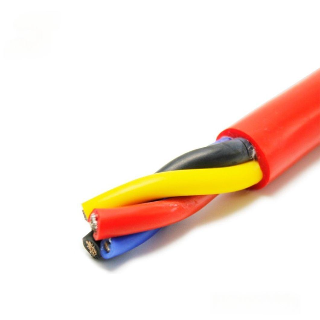
RST-WR vs RST-OR vs RST-IA: Three PUR Robot Cable Series for Three Wear Mechanisms
PUR robot cable series selection by dominant degradation mechanism
Three RST series use PUR jackets. Each is optimised for a specific dominant degradation mechanism — using the wrong series increases cost (over-specification) or reduces service life (under-specification). The selection boundary is the dominant failure mode in the installation, not the application type.
|
Selection criteria |
RST-IA — Standard flex |
RST-WR — Wear-resistant |
RST-OR — Oil-resistant |
|
Dominant degradation |
Conductor fatigue — no significant abrasion or chemical attack |
Mechanical jacket abrasion — chain/tray/roller contact |
Chemical jacket attack — cutting fluid, oil, weld spatter |
|
Jacket design |
88–90A PUR, 1.2–2.0 mm wall — optimised for flex recovery |
92A PUR, 2.0–3.5 mm wall — thick wear reserve budget |
Dual-hardness 95A+85A PUR — chemical barrier + flex balance |
|
Rated flex life |
≥ 5M cycles |
≥ 10M cycles |
≥ 5M dry / 4.4M post-immersion |
|
Oil resistance |
Group 1 (mineral oil) only |
Group 1 + light Group 2 (mist/splash) |
Group 2 (cutting fluid flood) |
|
Select when… |
Clean robot arm wiring; cable tray without continuous abrasion |
High-cycle drag chain / cable carrier; tray edge or guide roller contact without flood coolant |
Machining centre, grinding cell, welding workcell with cutting fluid or weld spatter |
|
Do NOT select when… |
Cable tray shows visible jacket wear within 12 months |
Flood coolant or weld spatter is present (specify RST-OR) |
Chain wear without coolant (RST-WR gives longer life at lower cost) |
RST-WR Series Product Matrix
Wear-resistant PUR robot cable — thick-wall configurations
All RST-WR: Class 6 conductors, ether-type PUR 92 Shore A, ≥ 10M flex cycles (signal/control) or ≥ 5M (power). Jacket wall column shows outer PUR 92A wall thickness.
|
Model |
Cores×mm² |
Shield |
Flex life |
OD (mm) |
Min bend R |
Jacket wall |
Primary use |
|
RST-WR-110 |
4×0.34 mm² |
None |
≥10M |
7.0±0.3 |
4×OD = 28 mm |
2.2 mm |
High-cycle I/O, sensor |
|
RST-WR-120 |
4×0.75 mm² |
None |
≥10M |
8.8±0.3 |
4×OD = 35 mm |
2.5 mm |
Control, 24 V DC drag chain |
|
RST-WR-130 |
7×0.75 mm² |
None |
≥10M |
11.5±0.4 |
4×OD = 46 mm |
2.8 mm |
Multi-axis drag chain I/O |
|
RST-WR-140 |
12×0.75 mm² |
None |
≥10M |
14.5±0.4 |
4×OD = 58 mm |
3.0 mm |
Full-bundle continuous axis |
|
RST-WR-210 |
4×0.34 mm² |
Cu braid ≥88% |
≥10M |
8.5±0.3 |
5×OD = 43 mm |
2.2 mm |
Shielded signal, high-cycle |
|
RST-WR-220 |
4×0.75 mm² |
Cu braid ≥88% |
≥10M |
10.5±0.3 |
5×OD = 53 mm |
2.5 mm |
Shielded control drag chain |
|
RST-WR-310 ① |
3×1.5 mm² |
None |
≥5M |
11.5±0.4 |
4×OD = 46 mm |
2.5 mm |
Power feed, continuous axis |
|
RST-WR-320 ① |
3G×2.5 mm² |
None |
≥5M |
13.5±0.4 |
4×OD = 54 mm |
3.0 mm |
Heavy-duty power, carrier rail |
|
RST-WR-C (ETO) |
Per spec |
Per spec |
Per design |
4–22 mm |
Per OD |
Up to 4.5 mm |
LSZH · > 10 m/s wear · ultra-heavy |
① Power variant 5M vs signal/control 10M: 1.5–2.5 mm² conductors produce higher absolute bending stress at the same 4× OD radius than 0.34–0.75 mm² conductors (stress ∝ d_wire × OD/R, where larger OD at 4× = same strain but conductor wire diameter is proportionally larger). Fatigue life scales as (stress)^−3.5 — the larger conductors reach their endurance limit at approximately 50% of the small-conductor life. This is why power models are rated 5M, not 10M.
Installation Parameters and Jacket Inspection Criteria
Drag chain installation limits and their effect on RST-WR jacket wear rate
|
Parameter |
Standard range |
Out-of-range condition |
Wear rate effect and correction |
|
Chain fill ratio |
≤ 60% trough area |
Cable-on-cable contact |
Cable-on-cable contact produces 2–3× higher wear rate than cable-on-chain-inner-surface. PUR-on-PUR friction generates more surface energy than PUR-on-steel. Separate cables with foam spacers if fill must exceed 60%. |
|
Traverse speed |
≤ 5 m/s |
> 5 m/s — raised impact energy at reversal |
Apply speed correction: life × 1/(v/5)^1.5 where v is traverse speed. Conservative table: 5–10 m/s → 0.7× correction. > 10 m/s → specify ETO. Based on Hertz contact: wear rate ∝ v^1.5 (contact pressure ∝ v, wear ∝ pressure^1.5). |
|
Inner radius |
≥ 4× OD (unshielded); ≥ 5× OD (shielded) |
Below minimum — cable under tensile stress while contacting chain surface |
Stress-assisted abrasion: jacket is simultaneously stretched (tensile stress on outer radius) and abraded. Tensile stress reduces the surface yield strength, increasing scratch depth per contact event by 3–5×. Never install below minimum radius. |
|
Free cable length |
Chain mfr. spec (typically travel × 1.10–1.15) |
Excess length — cable drags on lower trough surface |
Excess length causes the cable to sag against the lower chain surface at mid-stroke, converting the contact from intermittent (chain reversal only) to semi-continuous (full stroke). Wear rate increases 3–5× because duty cycle increases from ~15% to ~60%. |
Jacket inspection criteria — when to replace RST-WR
|
Inspection check |
Observation |
Assessment |
Action |
|
Outer jacket thickness at tray contact point |
Remaining wall ≥ 0.8 mm above conductor insulation |
Within specification — electrical protection maintained |
Continue service; re-measure at next planned maintenance |
|
Outer jacket thickness at tray contact point |
Remaining wall < 0.8 mm |
Wear approaching limit — schedule replacement |
Replace at next planned shutdown — do not wait for failure |
|
Conductor resistance |
R increase > 5% vs initial measurement |
Conductor fatigue approaching end of life — independent of jacket condition |
Replace immediately — conductor fatigue is the designed end-of-life failure mode for RST-WR |
|
Axis cycle counter |
Counter ≥ 8M cycles (80% of rated 10M) |
80% of rated life consumed — plan replacement |
Schedule replacement at next planned maintenance window |
Frequently Asked Questions
How is the 0.7× speed correction factor for PUR robot cable above 5 m/s derived?
The correction is based on Hertz contact theory for cylindrical contact (cable on flat chain surface). At chain reversal, kinetic energy scales as v² — this energy is absorbed as contact deformation. Hertz contact pressure scales as (contact force)^(1/2), and since force ∝ v², contact pressure ∝ v. Archard’s wear law for polymer-on-steel contact gives wear rate ∝ pressure^n where n ≈ 1.5 for PUR. Combined: wear rate ∝ v^(1×1.5) = v^1.5. From 5 m/s to 10 m/s: wear rate ratio = (10/5)^1.5 = 2.83×; life correction = 1/2.83 = 0.35×. The 0.7× correction is conservative (applies the average of 1.0× at 5 m/s and 0.35× at 10 m/s = 0.675×, rounded to 0.7×). For precise life calculation at a specific speed: life = 10M × (5/v)^1.5.
Why is the 10M flex life rating set by conductor fatigue rather than jacket wear?
The Taber abrasion calculation shows that at 11 mg/1,000 cycles and PUR density 1.22 g/cm³, the jacket wears at 0.015 mm per 1,000 Taber cycles. With a 2.0 mm wall, theoretical exhaustion is at 133,000 × 1,000 Taber cycles = 133M cycles. Real drag chain contact is 15–30× less aggressive than the Taber test (lower contact force, intermittent contact, lower relative velocity). At 20× lower: exhaustion at 2,660M cycles — 266× the rated 10M. The Class 6 conductor endurance limit under 4× OD bending is approximately 10–12M cycles for 0.75 mm² conductors. The 10M rating reflects conductor fatigue — jacket wear has a > 130× safety margin at that cycle count.
Can RST-WR be used in a machining cell with cutting fluid?
RST-WR is not designed for flood cutting fluid environments. It meets IEC 60811 Group 1 (mineral oil) and light Group 2 (mist and splash at 70°C tensile retention ≥ 70%), but in flood coolant applications where the cable is continuously wetted by water-soluble cutting fluid (pH 8.5–9.5 at use concentration), the Group 2 pass criterion is 75% tensile retention — the standard RST-WR outer compound meets Group 2 at 72%, below the 75% requirement. For machining cells with flood coolant, specify RST-OR, which uses a higher cross-link density outer compound certified at 78% Group 2 tensile retention. RST-WR is the correct choice for the same machine tool if the cable routing avoids flood coolant — for example, in the overhead cable carrier above the flood zone.
Request Samples or a Quotation
Specifying RST-WR PUR robot cable for your continuous motion application
For a complete first-reply response, include:
- Application: drag chain, cable carrier, robot arm, guide roller, or cable tray
- Traverse speed (m/s) — for speed correction factor calculation
- Cycle rate (cycles/hour) and annual operating hours
- Chain inner radius and trough width (for fill ratio check and minimum bend radius verification)
- Environment: dry, light oil mist, flood coolant, or other — determines RST-WR vs RST-OR selection
- Core count and cross-section; shielded or unshielded
- Quantity in metres or assembled sets with connector types
|
CONTACT |
Email: Jerry@rstlkable.com WhatsApp / Phone: +86 134 8219 7396 Address: No. 2591 Fengzhe Road, Fengxian District, Shanghai, China |