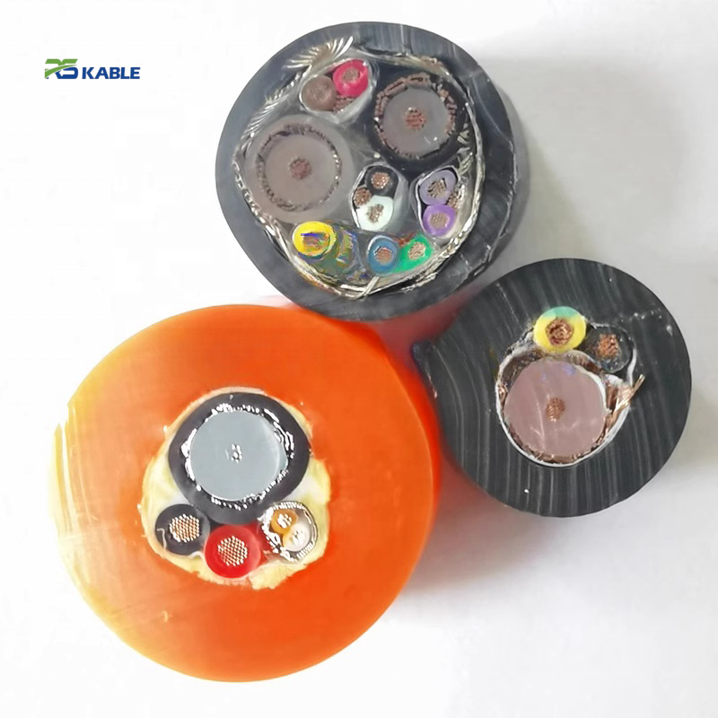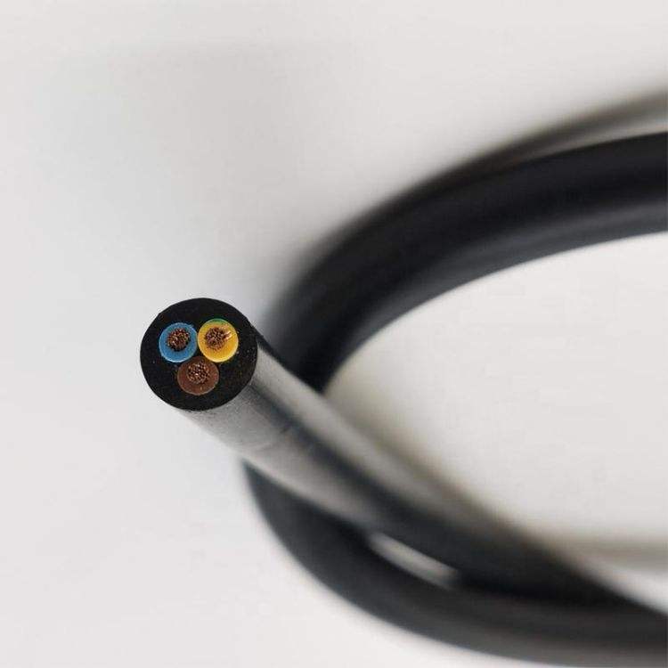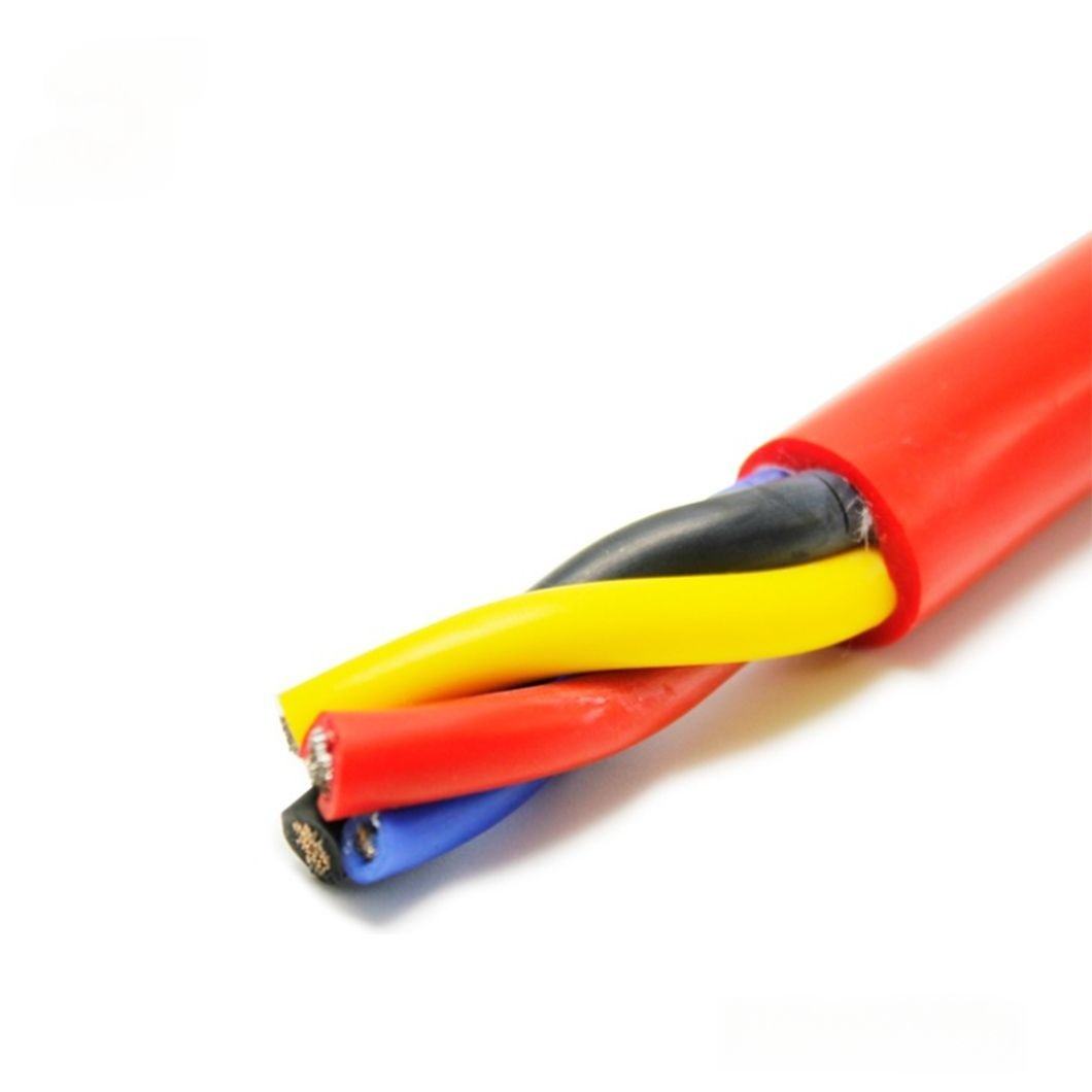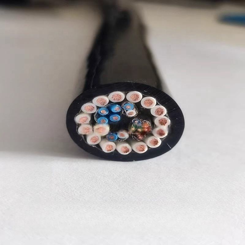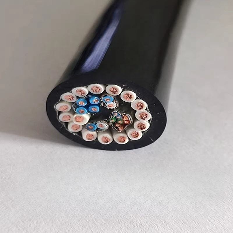
Shielded Robot Cable for Automation Systems with EMI and RFI Protection and Low Noise
Designed for robotic systems exposed to servo drives, VFDs, and switching noise, the RST-ES series maintains low transfer impedance under continuous motion. Shield performance is verified at the flex point, ensuring stable signal integrity throughout the cable’s service life.
Key Benefits:
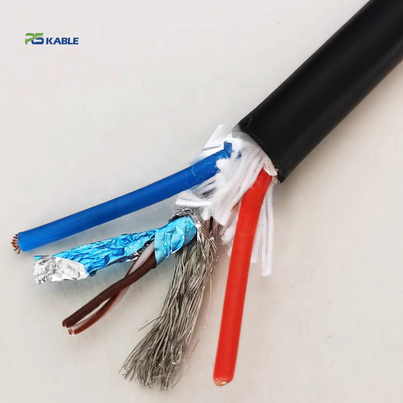
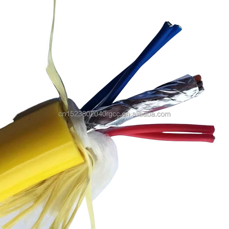
✅ Dual shielding (foil + braid) — TI ≤20 mΩ/m @ 1 MHz, stable after 5M cycles
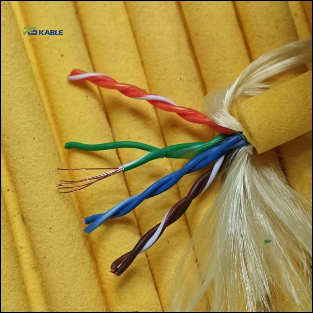
✅ Torsion-ready braid design — supports ±180°/m at robot joints
✅ Bonded drain structure — prevents shielding degradation during motion
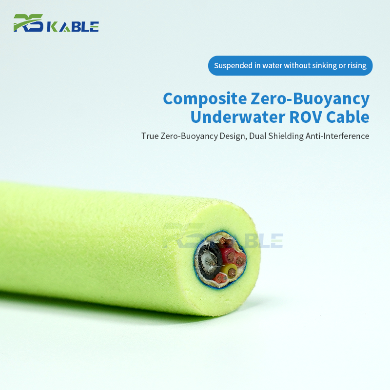
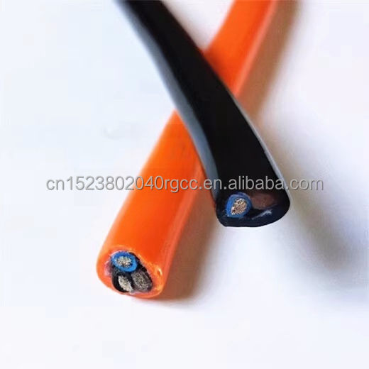
✅ Ether-based PUR jacket — oil resistant, hydrolysis-free, −40°C to +90°C
✅ Encoder-grade variants — enhanced shielding for high-precision signals
Shielded Robot Cable for Automation Systems with EMI and RFI Protection and Low Noise
The shielded robot cable specification sheet that an automation engineer receives from most suppliers shows transfer impedance measured on a straight, undisturbed cable sample at room temperature. In service, that same cable is held in a 5× OD arc at a robot wrist joint, simultaneously twisted at ±180°/m during every motion cycle. These two conditions produce fundamentally different TI values — and the difference determines whether your EMC margin calculation is accurate or optimistic by a factor of 3–7×.
The RST-ES series is specified with TI measured at the 4× OD bend reversal point under simultaneous torsion loading — the condition that represents actual service, not ideal laboratory conditions. This page is structured around three measurement questions: what TI do you need at each noise frequency, what TI does the RST-ES deliver at each flex checkpoint, and what grounding scheme is required to achieve the rated shielding performance in an installed robot arm.
Contents: frequency-domain noise source analysis with required shielding mechanism; silver drain wire TI improvement with physical mechanism; TI data across four frequencies and five flex checkpoints; product matrix; robot-specific grounding guide including joint bearing impedance effects; and field diagnostics with frequency-signature-first fault identification.
|
TI @ 1 MHz initial |
TI @ 1 MHz — 5M cyc |
Silver drain TI |
Shielding eff. @ 1M |
|
< 20 mΩ/m |
< 28 mΩ/m |
< 16 mΩ/m |
≥ 60 dB |
|
Pair foil + braid |
IEC 62153-4-3 flex tested |
RST-ES-310/320 encoder models |
IEC 62153-4-6 — Class C2 |

EMI Frequency Analysis: Matching Shield Mechanism to Noise Source
Shielded robot cable shielding performance is frequency-dependent — here is why
Transfer impedance is not a single-frequency property. A copper braid shield reaches its lowest (best) TI in the 100 kHz–1 MHz range where its optical coverage and low DC resistance combine most effectively. Above 1 MHz, braid inductance increases TI rapidly — a 90% coverage braid that shows TI = 15 mΩ/m at 1 MHz typically shows TI > 200 mΩ/m at 10 MHz. An aluminium foil, by contrast, has negligible inductance and maintains low TI above 1 MHz, but its thin wall thickness means it provides less attenuation at low frequencies than a thick braid.
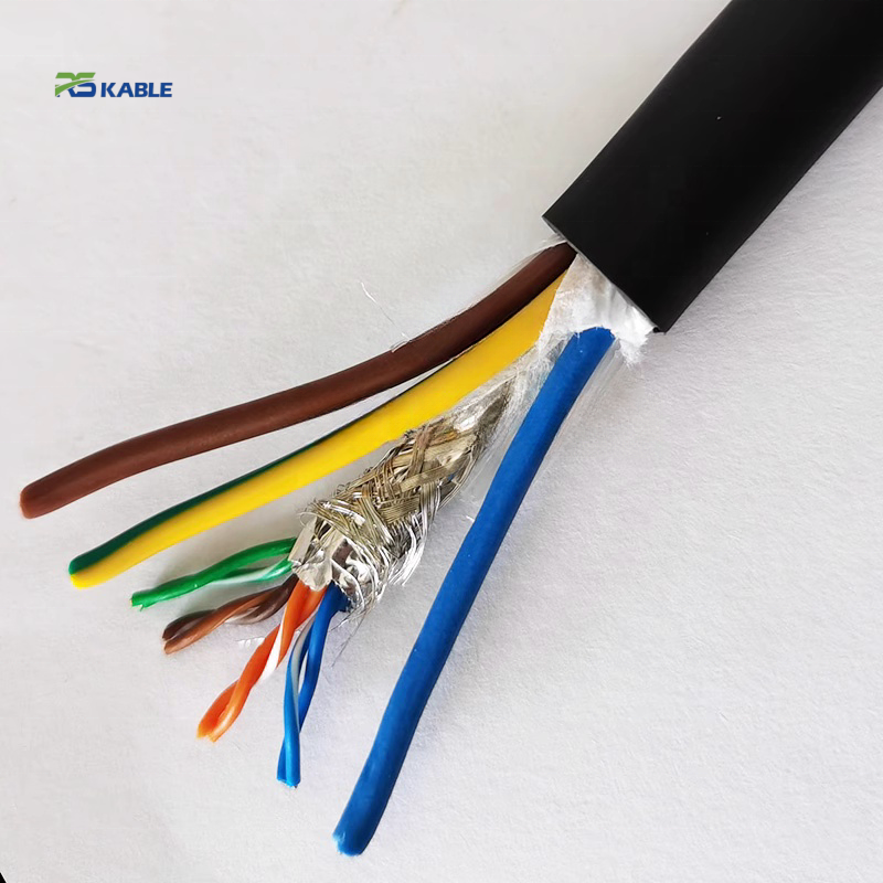
The correct shielding architecture depends on which noise source dominates in the specific automation cell. The two-layer RST-ES architecture — pair foil plus overall braid — covers both mechanisms simultaneously, but understanding which layer does what at which frequency allows the installer to diagnose failures and verify coverage with the right instrument at the right frequency.
Noise source to shielding mechanism mapping — automation workcell reference
|
Noise source |
Peak frequency |
Signal affected |
Required shield layer |
RST-ES TI at this freq. |
|
Servo drive switching |
4–16 kHz + harmonics to 100 kHz |
4–20 mA analogue, thermocouple |
Overall Cu braid (low DC resistance, low TI at 10–100 kHz) |
< 14 mΩ/m @ 100 kHz |
|
VFD common-mode current |
50 kHz – 1 MHz |
Digital 24 V I/O, relays |
Overall Cu braid + low-impedance PE termination |
< 20 mΩ/m @ 1 MHz |
|
Encoder edge rates |
1–10 MHz |
Encoder A/B/Z, SSI, BiSS-C |
Pair AL/PET foil (negligible inductance; maintains TI above 1 MHz where braid fails) |
< 20 mΩ/m @ 10 MHz (foil layer) |
|
Resolver excitation |
2–20 kHz; harmonics to 200 kHz |
Resolver sin/cos pairs |
Pair foil per resolver pair — prevents crosstalk between excitation and feedback pairs inside same cable jacket |
Pair isolation ≥ 55 dB @ 10 kHz |
|
Switch-mode power supply ripple |
100 kHz – 500 kHz |
24 V DC supply lines |
Overall braid — adequate; both-ends grounding permissible for power (not signal) cables |
< 18 mΩ/m @ 500 kHz |
Silver Drain Wire: Why Drain Contact Resistance Determines Shielded Cable TI
The transfer impedance equation — how drain wire resistance appears in the shielding calculation
Most shielded robot cable datasheets focus on braid optical coverage percentage. A 95% coverage braid looks more impressive than 88% coverage. But coverage percentage does not determine TI at 1 MHz — the drain wire contact resistance does, in combination with the shield inductance.
The simplified transfer impedance equation at frequency f is: TI ≈ √(R_drain² + (2πf · L_shield)²) / coverage_factor, where R_drain is the resistance from the foil to the external shield ground via the drain wire, and L_shield is the distributed shield inductance per unit length. At 1 MHz, the inductive term (2πf · L_shield) is typically 5–15 mΩ/m for a well-designed cable. R_drain adds in quadrature with this inductive term.
This is why drain wire contact resistance matters even when it seems small. A bare copper drain wire against an aluminium foil, after 2–3 million flex cycles, develops oxide at the contact interface — reaching 1.5–3 Ω contact resistance. At this resistance, R_drain completely dominates the TI calculation: TI ≈ 1,500–3,000 mΩ/m — 75–150× worse than the initial specification. The shielding appears intact visually but provides essentially no attenuation.
Silver drain wire contact resistance through flex cycling — measured data
|
Flex checkpoint |
Bare Cu drain R (Ω) |
Silver drain R (Ω) |
TI impact @ 1 MHz |
Shielding assessment |
|
0 (new) |
0.12 Ω |
0.08 Ω |
Both negligible vs inductive term |
Both pass |
|
500,000 cycles |
0.38 Ω |
0.10 Ω |
Bare Cu begins contributing to TI |
Both pass |
|
1,000,000 cycles |
0.85 Ω |
0.12 Ω |
Bare Cu: TI rising to ~30 mΩ/m. Silver: no change |
Bare Cu borderline |
|
3,000,000 cycles |
1.82 Ω |
0.18 Ω |
Bare Cu: TI ~120 mΩ/m (drain-dominated). Silver: < 18 mΩ/m |
Bare Cu: fail |
|
5,000,000 cycles |
2.95 Ω (oxidised surface) |
0.22 Ω |
Bare Cu: TI ~230 mΩ/m (shielding functionally lost). Silver: < 22 mΩ/m |
Silver: pass |
|
TI EQUATION SUMMARY |
TI ≈ √(R_drain² + (2πf · L_shield)²) / coverage_factor At 1 MHz: inductive term (2πf · L_shield) ≈ 8–12 mΩ/m for RST-ES. Silver drain R_drain = 0.22 Ω at 5M cycles → contribution to TI = 0.22 mΩ/m — negligible. Bare copper drain R_drain = 2.95 Ω at 5M cycles → contribution = 2,950 mΩ/m — drain resistance completely dominates. Silver plating prevents the copper oxide layer that forms at the aluminium foil contact surface under repeated flex abrasion. Silver oxide has ~5× lower resistivity than copper oxide and forms at a 10× slower rate — this is the physical reason for the 10× better drain resistance retention at end of flex life. |

RST-ES Series Product Matrix
Shielded robot cable — standard configurations with silver-drain encoder models
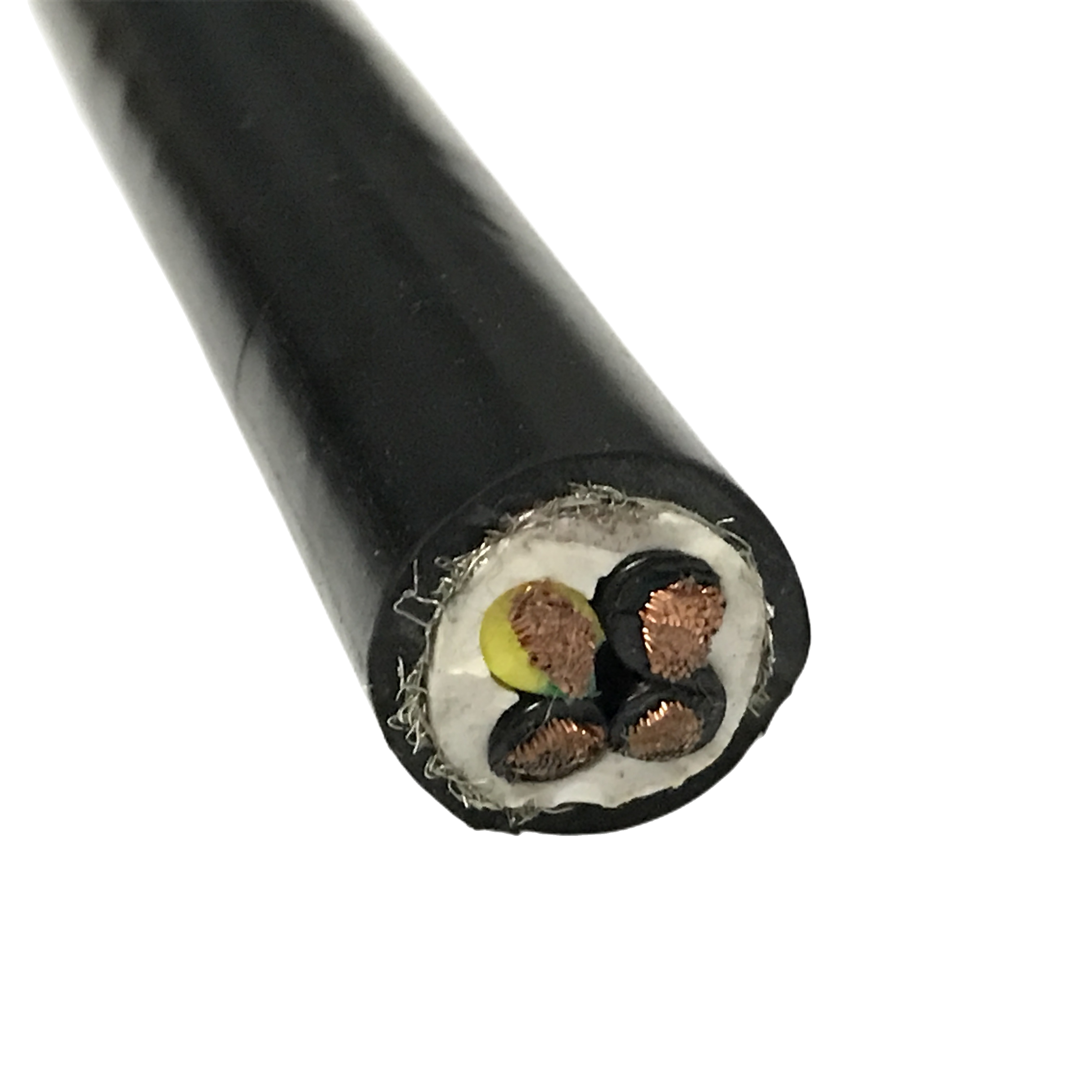
All RST-ES: IEC 60228 Class 6 conductors, foamed TPE filler, 32–38° braid weave angle, ether-type PUR 88 Shore A, ≥ 5M flex cycles. TI measured at 4× OD flex mid-point per IEC 62153-4-3.
|
Model |
Cores/pairs |
Shield |
Flex life |
OD (mm) |
TI@1MHz |
Min bend R |
Application |
|
RST-ES-110 |
4×0.34 mm² |
Cu braid |
≥5M |
6.5±0.3 |
<35 mΩ/m |
5× OD = 33 mm |
Digital I/O |
|
RST-ES-120 |
4×0.75 mm² |
Cu braid |
≥5M |
8.2±0.3 |
<35 mΩ/m |
5× OD = 41 mm |
Control wiring |
|
RST-ES-130 |
7×0.75 mm² |
Cu braid |
≥5M |
10.5±0.4 |
<35 mΩ/m |
5× OD = 53 mm |
Multi-core shielded I/O |
|
RST-ES-210 |
2pr×0.14 mm² |
Foil/pr + braid |
≥5M |
6.8±0.3 |
<20 mΩ/m |
5× OD = 34 mm |
Encoder / BiSS-C |
|
RST-ES-220 |
4×0.75 mm² |
Foil/pr + braid |
≥5M |
9.5±0.3 |
<20 mΩ/m |
5× OD = 48 mm |
Wrist joint control |
|
RST-ES-230 |
12×0.75 mm² |
Foil/pr + braid |
≥5M |
14.0±0.4 |
<20 mΩ/m |
5× OD = 70 mm |
Full I/O high-EMI |
|
RST-ES-310 ★ |
2pr×0.14 mm² |
Foil/pr + Ag braid |
≥5M |
7.0±0.3 |
<16 mΩ/m |
5× OD = 35 mm |
High-res. abs. encoder |
|
RST-ES-320 ★ |
4pr×0.25 mm² |
Foil/pr + Ag braid |
≥5M |
9.5±0.3 |
<16 mΩ/m |
5× OD = 48 mm |
Multi-encoder / resolver |
|
RST-ES-410 |
3×1.5+4×0.75 |
Signal foil+braid |
≥3M |
15.0±0.5 |
<25 mΩ/m |
5× OD = 75 mm |
Servo pwr + shld ctrl |
|
RST-ES-500 (cobot) |
4×0.75 mm² |
Foil/pr + braid |
≥5M |
9.5±0.2 |
<20 mΩ/m |
5× OD = 48 mm |
ISO/TS 15066 PFL cobot |
|
RST-ES-C (ETO) |
Per spec |
Per spec |
Per design |
4–22 mm |
Per spec |
Per OD |
LSZH / ±270°/m |
★ Silver drain models: RST-ES-310/320 use silver-coated OFC drain wire at the pair foil contact. Silver oxide resistivity is 5× lower than copper oxide and forms 10× more slowly — drain contact resistance after 5M cycles: 0.22 Ω (silver) vs 2.95 Ω (bare copper). This 13× better retention in R_drain directly translates to TI < 16 mΩ/m vs < 28 mΩ/m at 5M cycles. Required for high-resolution absolute encoders (e.g. Heidenhain EnDat 2.2, Siemens DRIVE-CLiQ) where encoder count errors require TI < 20 mΩ/m at 1 MHz across full service life.
Complete Technical Specification
Shielded robot cable conductor, shielding, and filler parameters
|
Parameter |
Specification |
|
Conductor |
IEC 60228 Class 6; 0.14 mm²: ≥100 wires; 0.34 mm²: ≥130 wires; 0.75 mm²: ≥196 wires; individual wire ≤ 0.10 mm; helical lay 15–20° per OD |
|
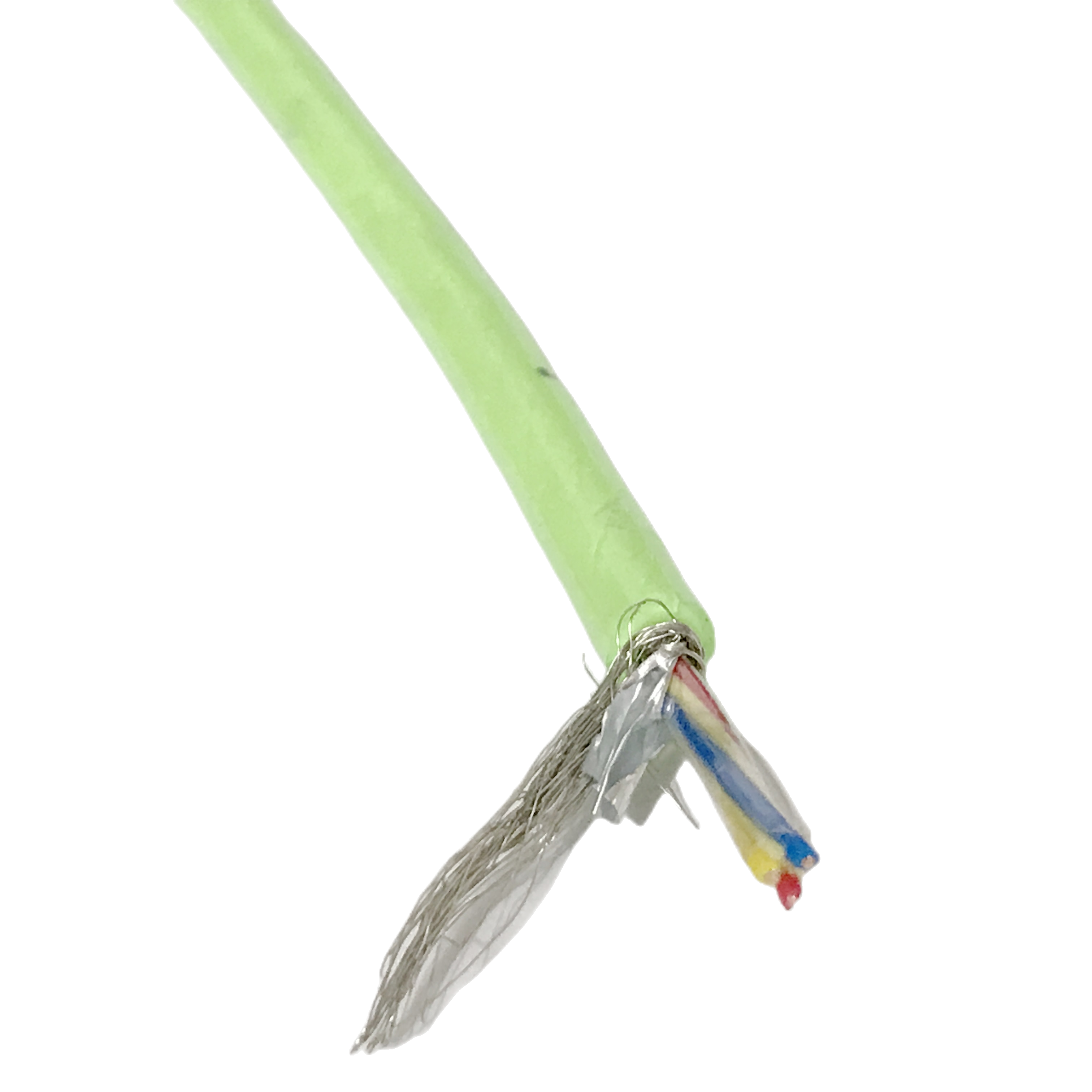
Pair shield |
AL/PET foil 100% coverage; drain wire 0.5 mm² OFC (standard) or silver-coated OFC (RST-ES-310/320); bonded at 60 mm — tighter than panel automation cables (80 mm) due to higher torsion at robot wrist |
|
Overall braid |
Tinned Cu braid; coverage ≥ 88% initial; ≥ 85% at 5M cycles; weave angle 32–38° — validated for ±180°/m torsion without wire abrasion (> 42°) or coverage collapse (< 28°) |
|
TI — pair foil + braid |
Standard models: < 20 mΩ/m initial; < 28 mΩ/m @ 5M cycles. Silver drain models: < 16 mΩ/m initial; < 22 mΩ/m @ 5M cycles. All measured at 4× OD flex mid-point per IEC 62153-4-3 |
|
TI — overall braid only |
< 35 mΩ/m initial; < 42 mΩ/m @ 5M cycles @ 1 MHz |
|
Shielding effectiveness |
≥ 60 dB @ 1 MHz; ≥ 48 dB @ 10 MHz per IEC 62153-4-6. IEC 61800-3 Category C2 compliance: C2 requires EN 55011 Class A (≥ 40 dB margin @ 30 MHz at 10 m) — RST-ES ≥ 48 dB @ 10 MHz provides 8 dB additional margin |
|
Pair-to-pair isolation (foil models) |
≥ 55 dB @ 10 kHz; ≥ 42 dB @ 1 MHz between adjacent pairs — prevents encoder signal from coupling into adjacent analogue pair in combined cables |
|
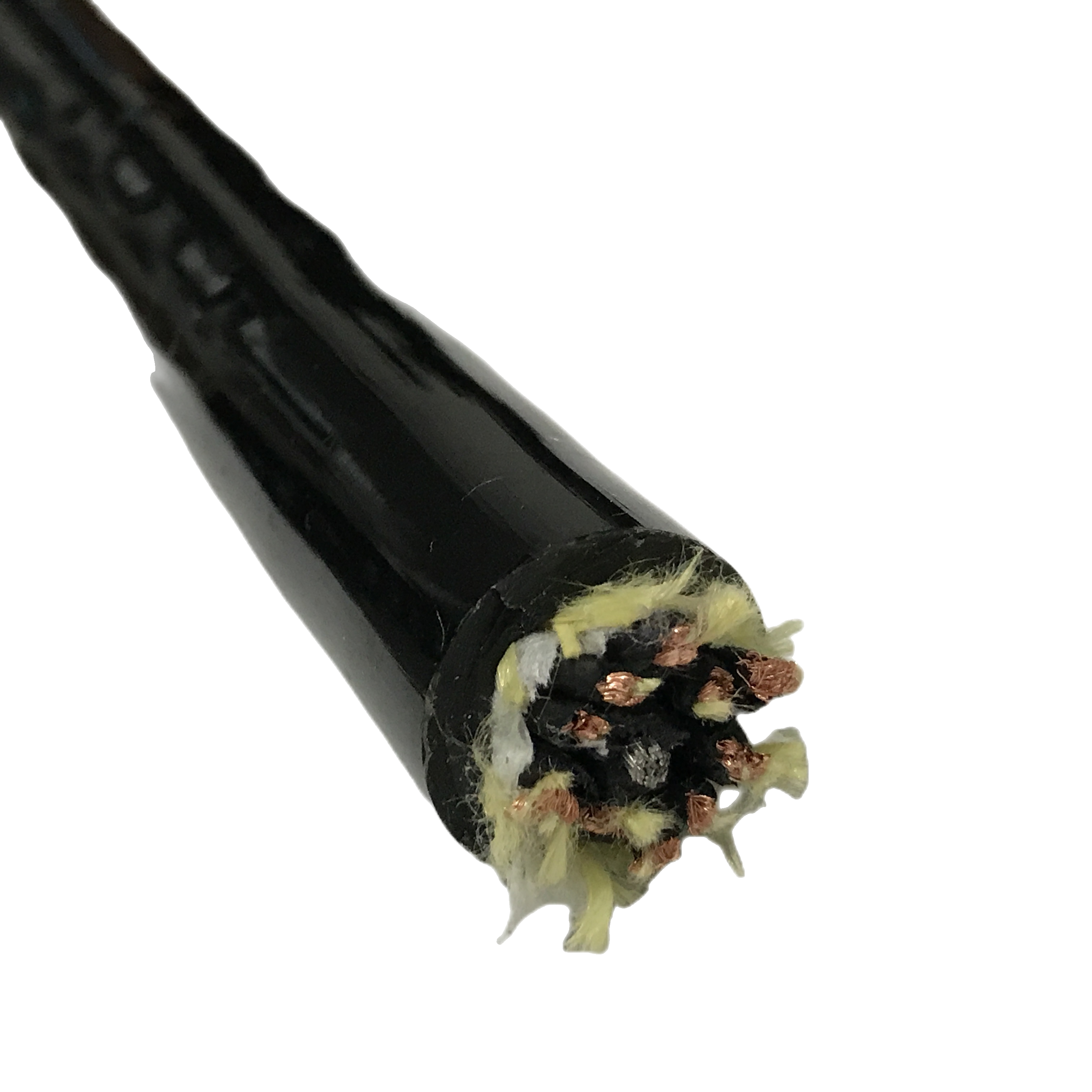
Core filler |
Foamed TPE elastomer 45–55 Shore A; ovality ≤ 3.2% at 5M cycles; accommodates diagonal compression under torsion loading. Serves layer (polyester textile) between core and jacket allows ±5° core rotation under torsion |
|
Jacket |
Ether-type PUR 88 Shore A; −40°C to +90°C; Group 1 oil resistance ≥ 80% tensile retention (7-day immersion at 70°C per IEC 60811-2-1); cold flex −40°C no cracking at 5× OD |
|
Min bend radius |
5× OD dynamic (all shielded RST-ES). Bending stiffness ratio vs unshielded: foil +30% + braid +22% = 1.52× → minimum radius scales as √1.52 × 4× OD ≈ 5× OD to maintain conductor stress below fatigue endurance limit |
Shield Grounding in Robot Installations: The Bearing Impedance Factor
Why shielded cable ground loops in robot arms are joint-angle-dependent
In a static panel installation, shield grounding is a fixed circuit — ground the shield at one end and the shield current path is constant. In a robot arm installation, the shield grounding path has a variable element that most installers do not account for: the electrical impedance of the robot structure between the end-effector chassis and the cabinet earth ground changes with every joint angle.
Robot joint bearing impedance — the variable element in the ground loop
Each robot joint consists of a bearing assembly that conducts electricity between the motor/gearbox housing and the arm structure. The contact resistance of a ball or roller bearing depends on the lubricant film thickness, the surface area of rolling element contact, and the number of rolling elements currently in the loaded zone. These parameters change continuously as the joint rotates.
Measured bearing impedance at typical robot joint sizes (bearing OD 80–150 mm): as the joint rotates through 360°, the impedance between the inner and outer rings varies between approximately 0.2 Ω (multiple rolling elements in loaded zone, thin lubricant film) and 45 Ω (few elements in loaded zone, thick lubricant film at low-contact positions). This 225× impedance variation makes the ground loop resistance through the robot structure a periodic function of joint angle.
The consequence: if a shield is grounded at both the encoder end and the controller cabinet end via the robot structure, the ground loop current — and therefore the resulting 50 Hz signal noise — varies as a function of joint angle. The noise appears at specific angles and disappears at others. This joint-angle-dependent 50 Hz noise pattern is the diagnostic fingerprint of a ground loop through the robot structure, and should be identified before suspecting cable shielding failure.
Grounding scheme by signal type — with robot-specific notes
|
Signal type |
Controller end |
Sensor/encoder end |
Robot-specific grounding note |
|
Encoder / resolver |
Shield to PE rail |
Float or 10 nF cap to PE |
If noise is joint-angle-dependent (appears/disappears at specific positions): suspect ground loop via robot structure. Test: clamp meter on shield at arm mid-point with drives disabled. If > 5 mA: path through robot chassis exists — float at encoder end. |
|
4–20 mA analogue |
Shield to PE at receiver |
Float at transmitter |
Analogue ground loops have a characteristic 50 Hz or 100 Hz hum. If hum amplitude varies with joint angle: bearing impedance modulation confirms robot-structure ground loop. Fix: insulate shield at transmitter end from robot chassis using a non-conductive grommet at the connector backshell. |
|
Thermocouple / PT100 |
Shield to PE at controller |
Float — never connect at sensor |
Thermocouple mV-range signals are the most sensitive to ground loops. A 45 Ω bearing impedance variation with 1 mA ground loop current produces 45 mV noise — exceeding the full-scale thermocouple output for a 5°C temperature range. Keep sensor-end shield strictly floating. |
|
24 V DC digital I/O |
Shield to PE at PLC |
Float at sensor |
24 V I/O tolerates higher noise — ground-loop-induced noise rarely causes problems unless loop current exceeds 50 mA. Verify with clamp meter: > 50 mA shield current at any joint angle with drives enabled and shield grounded at both ends = ground loop present. |
|
Safety relay / E-stop |
Shield to PE at safety controller |
Both-ends PE acceptable |
Safety circuits permit both-ends grounding because noise tolerance is high and both-ends PE provides additional surge protection. However, if the safety system has a self-diagnosis function that monitors loop current, confirm the ground loop current does not trigger a false fault. |
|
SHIELD CURRENT DIAGNOSTIC THRESHOLDS |
Test: clamp current meter on outer braid of shielded cable at robot arm mid-point. < 10 mA with drives disabled: normal capacitive leakage — no ground loop. > 50 mA with drives disabled: ground loop via robot structure — shield grounded at both ends through chassis. Float shield at sensor/encoder end. < 50 mA with drives enabled at full load: normal drive switching current — single-end grounding is correct. > 200 mA with drives enabled: shield carrying return current for drive CMC — check drive cabinet PE bonding and motor cable routing. |

Field Diagnostic Reference: Identifying EMI Faults by Frequency Signature
Diagnosing shielded robot cable EMI failures — frequency-first approach
The frequency of the noise identifies the source before any cable or shield measurement is needed. The table below uses noise frequency as the first diagnostic column — measure the noise with an oscilloscope or spectrum analyser before opening the cable conduit.
|
Noise frequency |
Noise source identified |
Signal affected |
Confirming cable test |
Correction |
|
50 / 100 Hz — varies with joint angle |
Ground loop via robot joint bearing impedance |
Any analogue or encoder signal |
Clamp meter on braid: > 5 mA with drives disabled = ground loop via robot chassis |
Float shield at sensor/encoder end. Use non-conductive grommet at connector backshell to prevent chassis contact. If 10 nF cap-to-PE is used at sensor end, verify capacitor is rated ≥ 500 V DC to handle induced surge voltages. |
|
50 Hz — fixed amplitude, not joint-angle-dependent |
Ground loop: both-ends shield grounding through fixed earth impedance difference |
Analogue, thermocouple |
Disconnect shield at sensor end temporarily. If 50 Hz disappears: both-ends grounding confirmed |
Float shield at sensor end. Fixed-amplitude 50 Hz (vs joint-angle-varying) indicates a static ground loop — two earth points with different potentials, not robot structure impedance modulation. |
|
4–16 kHz and harmonics |
Servo drive switching — braid TI insufficient or degraded |
Analogue 4–20 mA |
TI measurement at 10 kHz at wrist bend position: > 50 mΩ/m = braid degraded or weave angle wrong |
If TI within spec: verify single-end grounding and 100 mm+ separation from servo power cable. If TI above spec: replace with RST-ES-220 (32–38° braid, 60 mm drain bond). Confirm drain-to-braid resistance < 0.5 Ω at fault position. |
|
1–10 MHz — count errors at high speed |
Encoder edge rate coupling — braid alone insufficient above 1 MHz |
Encoder A/B/Z, SSI, BiSS-C |
TI at 10 MHz: braid-only cable > 100 mΩ/m at this frequency (expected); foil+braid cable > 40 mΩ/m at 10 MHz after 3M cycles = silver drain upgrade required |
Upgrade from RST-ES-210/220 to RST-ES-310/320 (silver drain, TI < 16 mΩ/m initial / < 22 mΩ/m at 5M cycles). At 10 MHz, braid TI > 300 mΩ/m — the pair foil is the only effective shield layer at encoder frequencies. Silver drain maintains foil-layer effectiveness through full service life. |
Frequently Asked Questions
Why does a shielded robot cable need silver-coated drain wires for high-resolution encoders?
High-resolution absolute encoders (Heidenhain EnDat 2.2, Siemens DRIVE-CLiQ, multi-turn encoders > 20-bit resolution) require TI < 20 mΩ/m at 1 MHz across the cable’s full service life — not just at installation. Bare copper drain wire oxidises at the aluminium foil contact surface under repeated flex abrasion, reaching 1.5–3 Ω contact resistance after 3 million cycles. This drain resistance adds directly to TI via the equation TI ≈ √(R_drain² + (2πf·L)²)/coverage. At 2.95 Ω drain resistance, TI at 1 MHz rises to ~230 mΩ/m — 11× above the acceptable limit. Silver plating prevents copper oxide formation, maintaining < 0.22 Ω drain resistance and TI < 22 mΩ/m through 5M cycles.
What causes joint-angle-dependent 50 Hz noise, and is it a cable fault?
Joint-angle-dependent 50 Hz noise is not a cable fault — it is a grounding scheme error. The cause is a ground loop formed when the cable shield is connected to earth at both the encoder end and the controller cabinet end through the robot structure. The robot joint bearings have electrical impedance that varies between 0.2 and 45 Ω as the joint rotates, modulating the ground loop current and therefore the induced noise amplitude. The correction is to float the shield at the encoder end — either with a direct float or a 10 nF capacitor to PE for RF drain without DC path. Replacing the cable does not fix a grounding-scheme fault.
How does the RST-ES achieve IEC 61800-3 Category C2 compliance?
IEC 61800-3 Category C2 requires that the drive system meets EN 55011 Class A radiated emission limits — approximately 40 dB shielding effectiveness at 30 MHz over a 10 m measurement distance. The RST-ES provides ≥ 48 dB shielding effectiveness at 10 MHz (measured per IEC 62153-4-6), giving 8 dB additional margin above the C2 Class A limit. The IEC 61800-3 C2 assessment covers the complete drive system — cable, motor, and drive together. The RST-ES cable contribution is verified; the drive and motor contributions must be verified separately.
Can RST-ES cables be used in drag chain systems as well as robot arms?
Yes — all RST-ES models support both drag chain and robot arm service. Drag chain constraint: minimum bend radius ≥ 5× cable OD at chain inner radius (check product table ‘Min bend R’ column for each model). Robot arm constraint: free cable length ≥ (rotation angle ÷ 180) × 1.20 m at each joint for torsion compliance. Both constraints apply independently. For pure drag chain without robot arm torsion, unshielded RST-IA-1xx provides 4× OD minimum radius — specify RST-ES only when EMI shielding is required.
Request Samples, TI Test Data, or a Quotation
Specifying the correct shielded robot cable for your EMI and RFI requirements
Rousheng provides TI test reports at 1 kHz, 100 kHz, 1 MHz, and 10 MHz — measured at 4× OD flex mid-point — before order placement. For a complete single-reply response, include:
- Signal type: encoder (state resolution and protocol — EnDat, SSI, BiSS-C), analogue, digital, or combined
- Dominant noise source: servo drive type and switching frequency; VFD; both
- Robot arm joint or drag chain — affects drain bond pitch and minimum bend radius
- TI requirement at specific frequency if known from system EMC calculation
- Whether joint-angle-dependent noise is already occurring — indicates grounding scheme check required before cable replacement
- High-resolution encoder application: yes/no (determines standard vs silver drain model)
- Core count and cross-section (or signal list with current ratings)
- Cobot application: yes/no; ISO/TS 15066 mode (PFL or SSM)
- Quantity in metres or assembled cable sets with connector types
|
CONTACT |
Email: Jerry@rstlkable.com WhatsApp / Phone: +86 134 8219 7396 Address: No. 2591 Fengzhe Road, Fengxian District, Shanghai, China Sample requests: state RST-ES model, signal type, and required TI frequency point. |