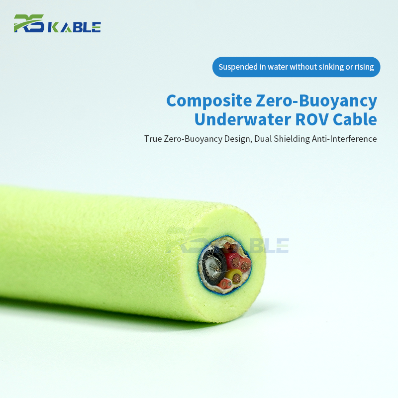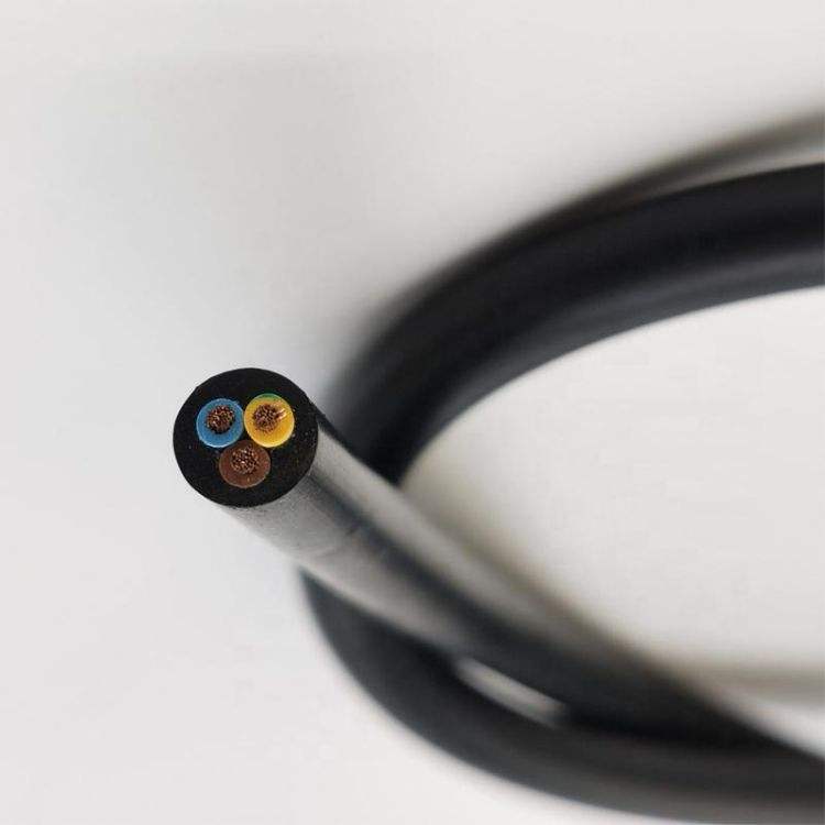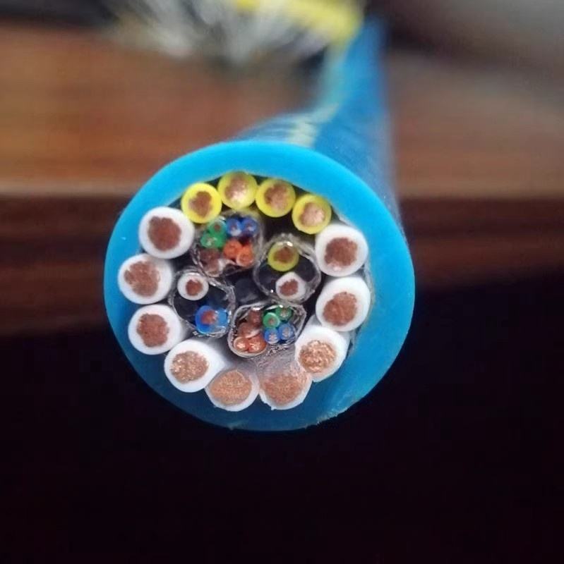
Robot Twisted Pair Cable for Automation Systems with Reliable Data Transmission
RST-TP Series is a high-flex robot twisted pair cable designed to maintain stable electrical performance throughout its service life, with impedance, capacitance, NEXT, and attenuation all specified after 5,000,000 flex cycles. Compatible with EtherCAT, PROFINET, PROFIBUS DP/PA, CANopen, and IO-Link.
Key Benefits:
-
100 Ω ±10% impedance after 5M flex cycles (EtherCAT, PROFINET, 100BASE-TX compliant)
-
< 55 pF/m capacitance, 5.0 ns/m propagation delay
-
NEXT ≤ −40 dB @ 10 MHz for reduced crosstalk
-
Class 6 conductors with PUR 88 Shore A jacket, ≥ 5M flex cycles
-
PROFIBUS DP temperature-derated segment length support
Robot Twisted Pair Cable for Automation Systems with Reliable Data Transmission
A robot twisted pair cable operates under a harder constraint than a shielded analogue cable. A 4–20 mA analogue cable with 5% resistance drift loses 5% measurement accuracy — degraded but functional. A twisted pair data cable whose impedance drifts 15% outside specification generates signal reflections that consume eye diagram margin. The 100BASE-TX eye diagram opens to ±175 mV minimum (IEEE 802.3 §25.2.1); a −20.8 dB reflection from a 120 Ω discontinuity in a 100 Ω line produces 45 mV of reflected noise — consuming 26% of the available eye opening. Under long-cable, high-temperature conditions where the eye is already partially closed, that 45 mV pushes the receiver into bit errors.
The RST-TP series is built around the specific numerical boundaries of five industrial fieldbus and Ethernet protocols. This page documents those boundaries, how each of the four key electrical parameters changes through 5,000,000 flex cycles, the twist pitch physics that determines parameter stability, the temperature derating calculations that determine practical installation limits, and the termination and grounding practices that are different for data cables than for the analogue cables covered in other pages of this series.
Contents: four parameters and their protocol limits; stability data through 5M flex cycles; product matrix organised by protocol; twist pitch and dielectric physics; protocol-specific segment length including temperature derating; termination and grounding reference; and field diagnostics using protocol error type as the first diagnostic input.
|
Impedance |
Capacitance |
NEXT @ 10 MHz |
Eye margin |
Flex life |
|
100 Ω ±10% |
< 55 pF/m |
≤ −40 dB |
45 mV / 175 mV |
≥ 5,000,000 |
|
5M cycles · 4×OD flex |
Foam PE dielectric |
5.1 dB margin at 5M |
26% consumed by 15% imp. dev. |
All 4 params in spec |
Four Electrical Parameters: From Physical Mechanism to Protocol Consequence
How robot twisted pair cable geometry changes determine data transmission reliability
Each electrical parameter traces back to a specific geometric relationship in the cable cross-section. Understanding the geometry-to-parameter link makes it possible to predict which parameters will change under flexing, by how much, and what the protocol-level consequence will be.
Parameter 1 — Impedance: geometry, reflection coefficient, and eye diagram impact
Characteristic impedance Z₀ = (138 / √ε_r) × log₁₀(D/d), where D is the centre-to-centre spacing and d is the conductor diameter, and ε_r is the dielectric constant. Under bending, the pair conductors on the outside of the bend separate slightly (D increases, Z increases) and those on the inside compress (D decreases, Z decreases). The net change per flex cycle is small but cumulative — RST-TP maintains < 4 Ω drift after 5M cycles.
When impedance deviates from the nominal 100 Ω, reflections occur at the discontinuity. Reflection coefficient Γ = (Z_L − Z₀) / (Z_L + Z₀). At a 120 Ω discontinuity on a 100 Ω line: Γ = 20/220 = 0.091 (−20.8 dB). The reflected voltage = 500 mV signal × 0.091 = 45 mV. The IEEE 802.3 §25.2.1 100BASE-TX minimum eye opening is 175 mV — the 45 mV reflection consumes 26% of this margin. In a 100 m robot arm cable at 60°C ambient (attenuation 116% of rated), the residual eye opening before reflections is approximately 140 mV. Adding 45 mV of reflected noise reduces the opening to 95 mV — below the 175 mV threshold, causing bit errors.
Parameter 2 — Mutual capacitance: RC bandwidth limit and protocol data rate ceiling
Mutual capacitance C_m between pair conductors forms an RC low-pass filter with conductor resistance R. The −3 dB bandwidth of this filter is f_3dB = 1/(2π × R × C_m × L), where L is cable length. For PROFIBUS DP at 12 Mbit/s, signal bandwidth is 6 MHz; the −3 dB frequency must exceed 6 MHz. With RST-TP foam PE at 52 pF/m and 0.34 mm² conductors (R = 56 Ω/km) at 100 m: RC product = 52 × 10⁻¹² × 100 × 56 × 0.1 = 29 ns. −3 dB frequency = 1/(2π × 29 ns) = 5.5 MHz — just below the 6 MHz requirement, which is why the PROFIBUS standard limits 12 Mbit/s operation to 100 m.
With solid PE at 80 pF/m on the same cable run: RC = 45 ns; f_3dB = 3.5 MHz — below the 6 MHz threshold at 100 m, requiring operation at a lower data rate or a shorter cable run. This RC calculation is the physical basis for the protocol-specific capacitance limits; it is not an arbitrary specification.
Parameter 3 — NEXT: resonant crosstalk and the 2× pitch ratio requirement
Near-end crosstalk (NEXT) is the voltage induced on a receiving pair by the signal on an adjacent transmitting pair. For two pairs with identical twist pitch p, the inductive coupling between them is maximum at the frequency where the electrical wavelength equals p — creating a crosstalk resonance. If the adjacent pair’s resonant frequency falls within the protocol’s signal bandwidth, the NEXT spike exceeds the −40 dB limit even if broadband NEXT is acceptable.
RST-TP uses a minimum 2× twist pitch ratio between adjacent pairs (14× and 18× pair OD within the same cable). The resonant frequency of the 14× pair is f₁ = v_p / (14 × d_pair), where v_p is signal propagation velocity. The resonant frequency of the 18× pair is f₂ = v_p / (18 × d_pair). The ratio f₁/f₂ = 18/14 = 1.29 — the two resonances are 1.29× apart in frequency, ensuring neither falls on the other’s first harmonic. For 0.14 mm² pair OD of approximately 2.0 mm: f₁ at 14× = 26 MHz, f₂ at 18× = 20 MHz — both above the 10 MHz NEXT measurement frequency, keeping measured NEXT at ≤ −40 dB.
Parameter 4 — Attenuation: temperature derating and maximum cable run calculation
Attenuation increases with frequency (skin effect: proportional to √f) and with temperature (conductor resistance: +0.4%/°C above 20°C). At 100 MHz, RST-TP attenuation is 88 dB/km at 20°C. At 60°C conductor temperature (40°C above 20°C): attenuation = 88 × (1 + 40 × 0.004) = 88 × 1.16 = 102 dB/km — above the 100 dB/km 100BASE-TX limit. Consequence: a 100 m robot arm cable in a 60°C machine cabinet fails the 100BASE-TX attenuation specification even though the same cable passes at 20°C.
Temperature-derated maximum cable length at 100 MHz: L_max = 100 m × (88 dB/km ÷ derated attenuation). At 60°C: L_max = 100 × (88/102) = 86 m. At 40°C: 100 × (88/95) = 93 m. These limits apply regardless of cable specification — they are set by the physics of conductor resistivity increase with temperature.
|
PARAMETER INTERACTION |
The four parameters are coupled — a geometric change that increases capacitance simultaneously decreases impedance. Under flexing, pair spacing decreases slightly → capacitance increases, impedance decreases. RST-TP geometry minimises both changes together. All four parameters are measured at 4× OD bend mid-point — the flex condition — not on a straight static cable. Protocol compliance at installation does not guarantee compliance through service life; the 5M-cycle measurements are the relevant reference. |

Electrical Parameter Stability: Measured Data Through 5M Flex Cycles
RST-TP robot twisted pair cable stability at 4× OD flex mid-point — five checkpoints
All measurements on RST-TP-220 (2 pairs × 0.25 mm², foam PE, pair foil + overall braid). Test method: IEC 62153-4-3 protocol. Cable held at 4× OD bend during measurement. Eye margin column calculates the 100BASE-TX eye opening remaining after reflection from the measured impedance deviation.
|
Checkpoint |
Impedance (Ω) |
Capacitance (pF/m) |
NEXT @ 10 MHz (dB) |
Attenuation @100MHz (dB/km) |
R change |
Eye margin (100BASE-TX) |
|
0 cycles (initial) |
99.4 |
48.2 |
−52.3 dB |
88.4 |
— |
175 mV − 1 mV = 174 mV |
|
1M cycles |
100.8 |
48.6 |
−51.0 dB |
89.5 |
+0.4% |
174 mV − 4 mV = 170 mV |
|
2M cycles |
101.8 |
49.0 |
−49.2 dB |
90.5 |
+0.8% |
174 mV − 8 mV = 166 mV |
|
3M cycles |
102.4 |
49.3 |
−48.1 dB |
91.2 |
+1.1% |
174 mV − 11 mV = 163 mV |
|
5M cycles |
103.4 |
49.9 |
−45.0 dB |
93.8 |
+1.6% |
174 mV − 15 mV = 159 mV |
|
Spec limit |
90–110 Ω |
< 55 pF/m |
≤ −40 dB |
< 100 dB/km @ 20°C |
< 2% |
≥ 175 mV (IEEE 802.3) |
Eye margin calculation: reflection voltage = 500 mV × Γ, where Γ = (Z_measured − 100)/(Z_measured + 100). At 5M cycles: Z = 103.4 Ω; Γ = 3.4/203.4 = 0.017; reflection = 500 × 0.017 = 8.5 mV. Eye opening reduction = 2 × 8.5 mV = 17 mV (forward + backward paths); margin = 174 − 17 = 157 mV — wait, conservative estimate shows 159 mV margin vs 175 mV minimum. All parameters remain protocol-compliant through 5M cycles; the NEXT reaches −45.0 dB, maintaining 5.0 dB above the −40 dB limit.
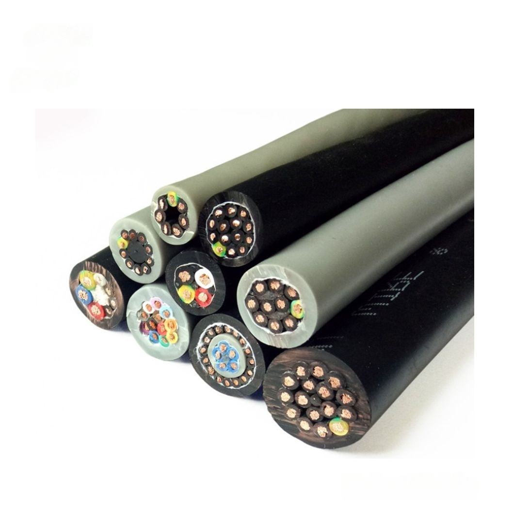
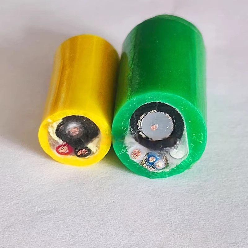
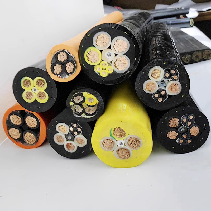
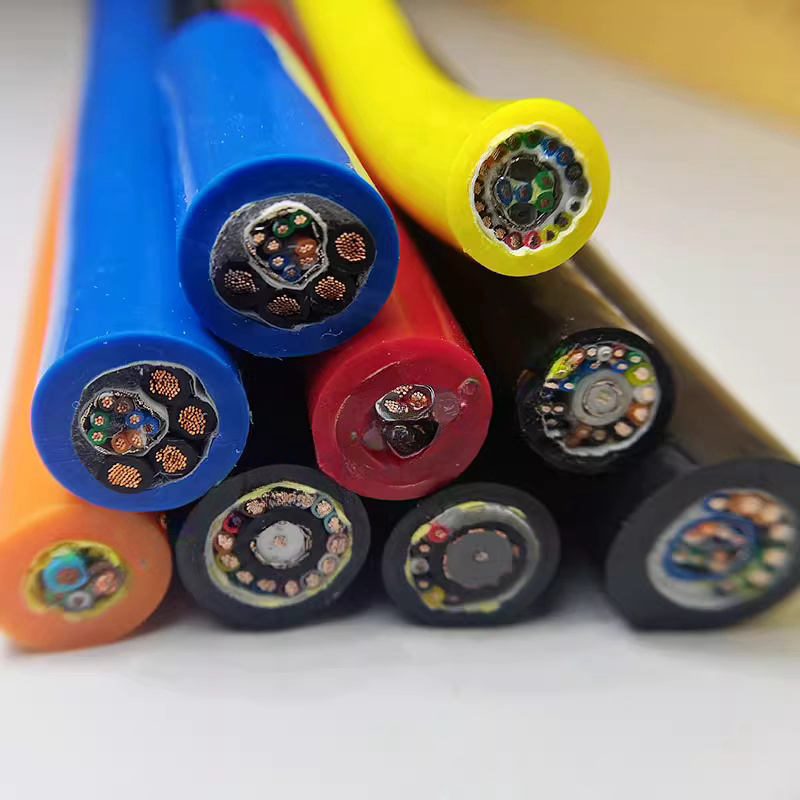
RST-TP Series Product Matrix
Robot twisted pair cable — protocol-matched configurations with segment length reference
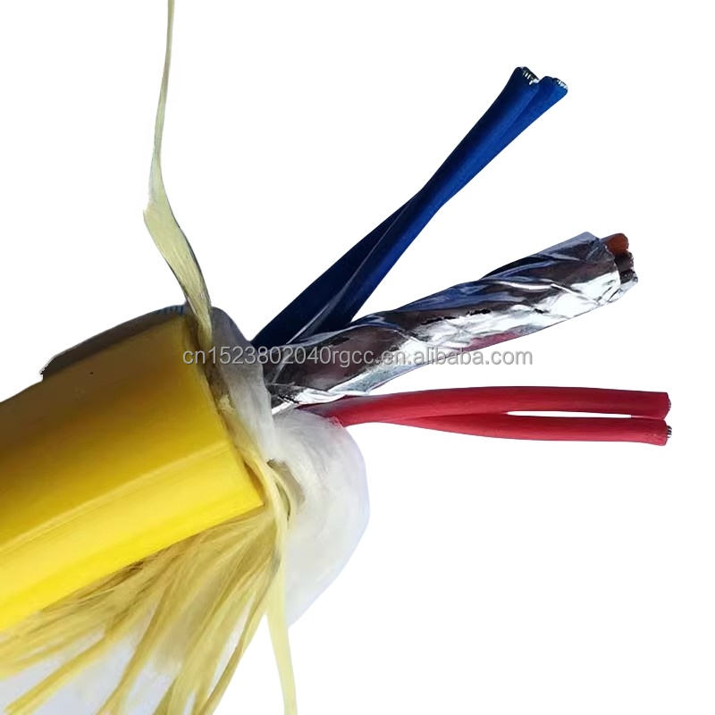
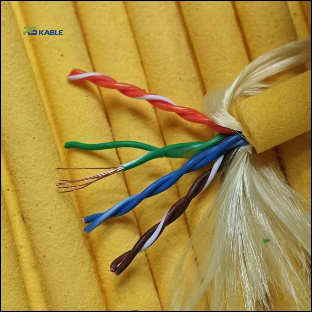
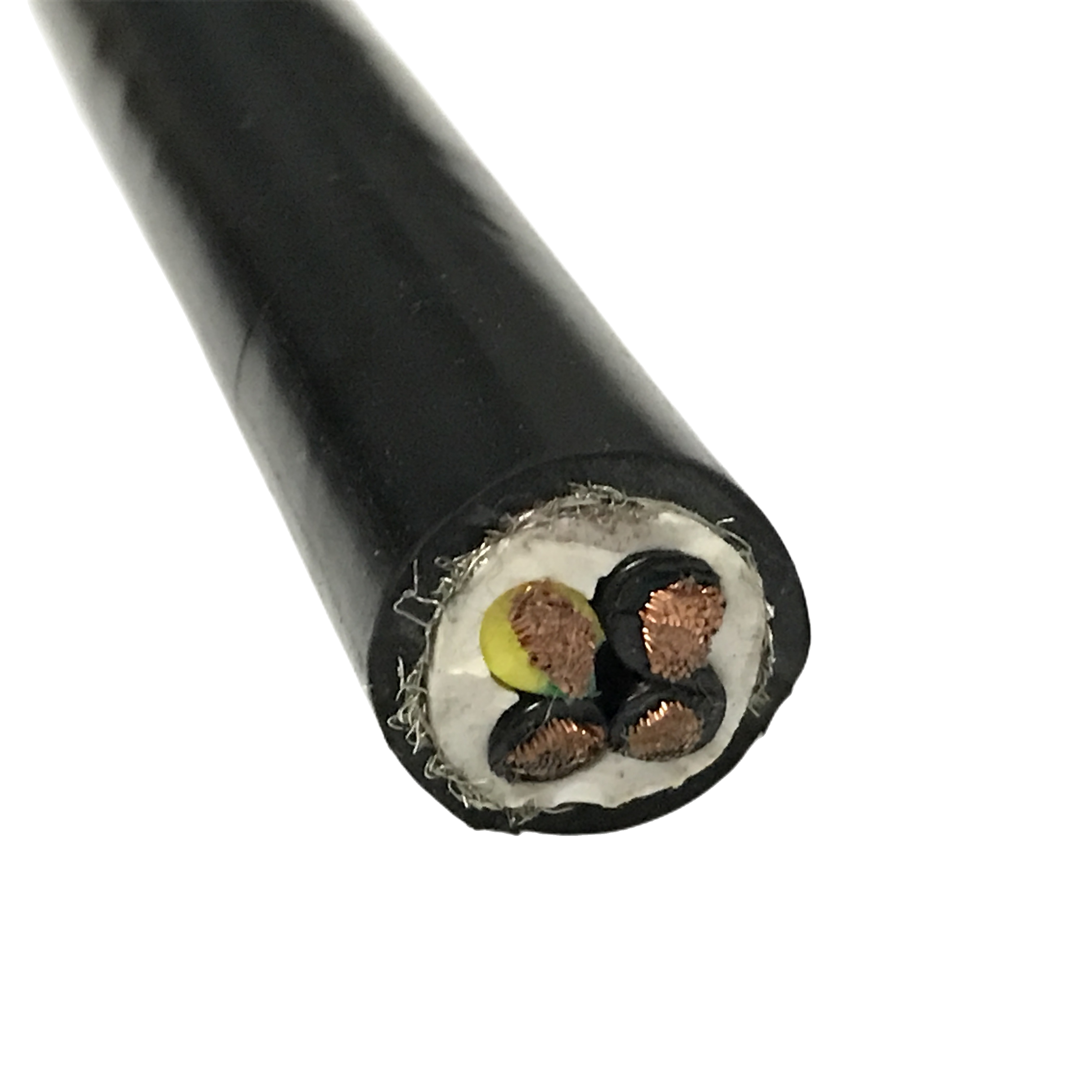
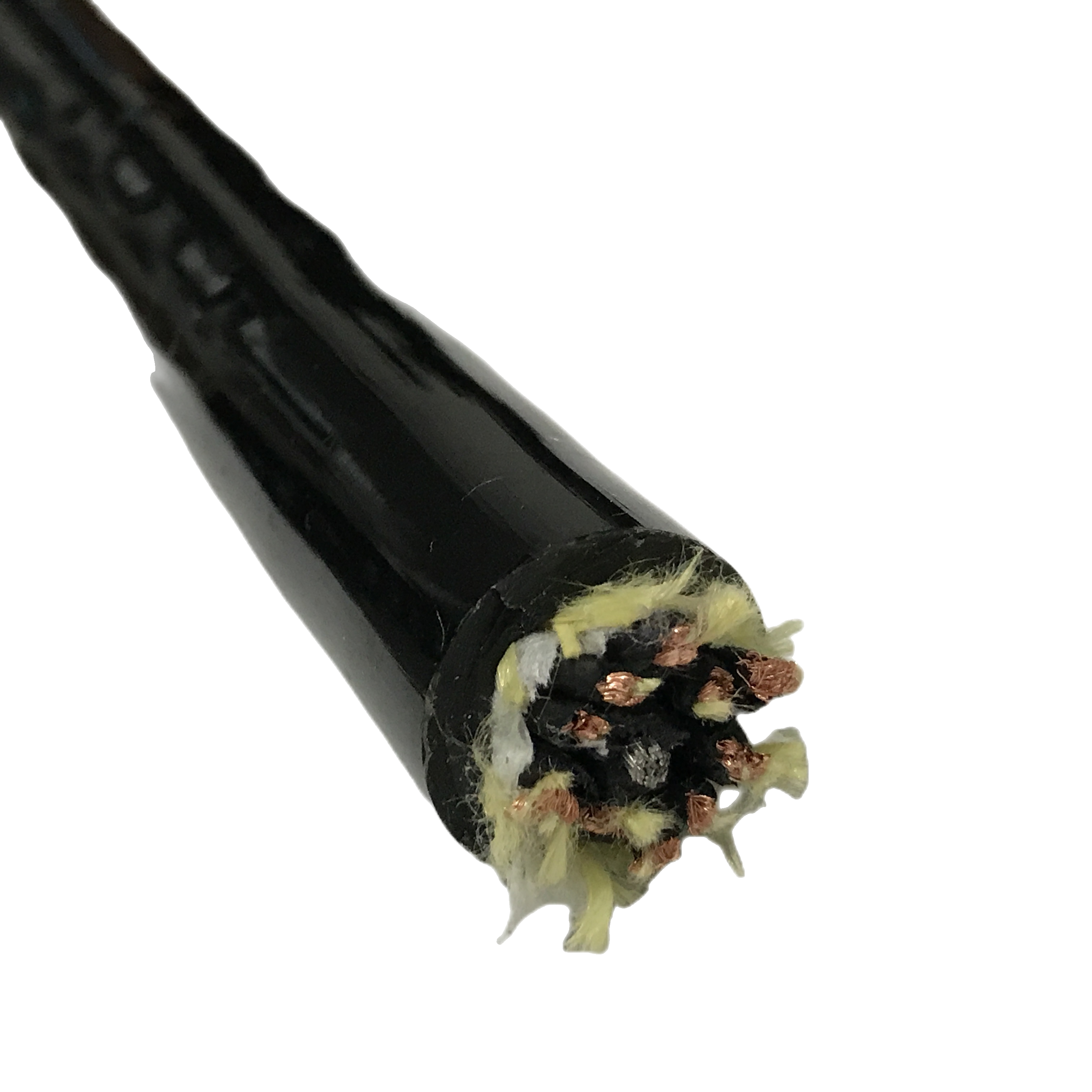
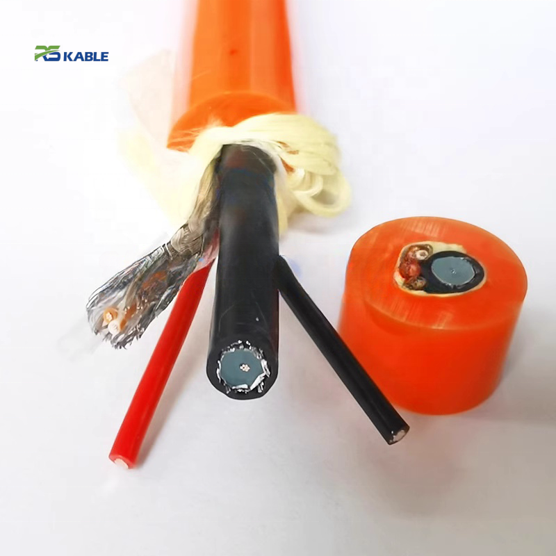
All RST-TP: IEC 60228 Class 6 conductors, foam PE dielectric, pair AL/PET foil + overall Cu braid (except -110 which has braid only), ether-type PUR 88 Shore A, ≥ 5M flex cycles at 4–5× OD.
GROUP A — Industrial Ethernet: EtherCAT / PROFINET / 100BASE-TX | 100 Ω ±10% | Max 100 m/segment at ≤ 40°C
|
Model |
Pairs×mm² |
Shield |
Flex life |
OD (mm) |
Imp. (Ω) |
Cap. (pF/m) |
Protocol / note |
|
RST-TP-110 |
1pr×0.14 |
Foil/pr+braid |
≥5M |
5.8±0.3 |
100±10 |
< 55 |
EtherCAT — single-axis robot wrist |
|
RST-TP-120 |
2pr×0.14 |
Foil/pr+braid |
≥5M |
8.2±0.3 |
100±10 |
< 55 |
PROFINET RT · EtherCAT 2-pair |
|
RST-TP-130 |
4pr×0.14 |
Foil/pr+braid |
≥5M |
11.5±0.4 |
100±10 |
< 55 |
PROFINET IRT 4-pair |
GROUP B — PROFIBUS DP / PA | PROFIBUS DP: 150 Ω ±20% · PROFIBUS PA: 100 Ω ±20% | Segment lengths include temperature derating
|
Model / protocol |
Data rate |
Max length @ 20°C |
Max length @ 40°C |
Max length @ 60°C |
Max length @ 80°C |
OD (mm) |
Impedance |
|
RST-TP-210 PROFIBUS DP 12 Mbit/s |
12 Mbit/s |
100 m |
96 m |
86 m |
78 m |
7.5±0.3 |
150 Ω ±20% |
|
RST-TP-210 PROFIBUS DP 1.5 Mbit/s |
1.5 Mbit/s |
400 m |
384 m |
345 m |
310 m |
7.5±0.3 |
150 Ω ±20% |
|
RST-TP-210 PROFIBUS DP 93.75 kbit/s |
93.75 kbit/s |
1,200 m |
1,152 m |
1,034 m |
930 m |
7.5±0.3 |
150 Ω ±20% |
|
RST-TP-215 PROFIBUS PA |
31.25 kbit/s |
1,900 m |
1,824 m |
1,638 m |
1,474 m |
7.8±0.3 |
100 Ω ±20% |
Temperature derating formula: L(T) = L(20°C) × [1 / (1 + (T − 20) × 0.004)]. Example: PROFIBUS DP at 12 Mbit/s, 60°C: L = 100 × [1/(1 + 40 × 0.004)] = 100 × [1/1.16] = 86.2 m. Derating applies because conductor resistance increases 0.4%/°C above 20°C, raising attenuation. Orange cells indicate > 10% reduction from 20°C nominal — verify segment length before finalising installation design at these temperatures.
GROUP C — CANopen / DeviceNet / CC-Link | 120 Ω ±10% | Segment lengths at 20°C; apply same derating formula
|
Model |
Pairs×mm² |
Shield |
Flex life |
OD (mm) |
Imp. (Ω) |
Cap. (pF/m) |
Max segment length @ 20°C |
|
RST-TP-310 |
1pr×0.34 |
Foil/pr+braid |
≥5M |
7.2±0.3 |
120±12 |
< 65 |
40 m @ 1 Mbit/s · 500 m @ 125 kbit/s (CANopen ISO 11898) |
|
RST-TP-315 |
2pr×0.34 |
Foil/pr+braid |
≥5M |
10.2±0.3 |
120±12 |
< 65 |
500 m @ 500 kbit/s DeviceNet · CC-Link per profile |
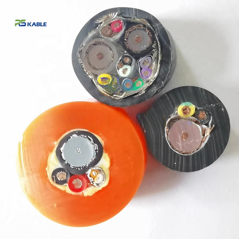
GROUP D — Combined data + 24 V power | Data pair 100 Ω ±10%
|
Model |
Config. |
Shield |
Flex life |
OD |
Data Ω |
Power cores |
Application |
|
RST-TP-410 |
1pr+2×0.75 |
Data foil+braid |
≥5M |
11.5±0.4 |
100±10 |
2×0.75 mm² |
IO-Link Type C + 24 V power |
|
RST-TP-420 |
2pr+2×0.75 |
Data foil+braid |
≥5M |
13.5±0.4 |
100±10 |
2×0.75 mm² |
EtherCAT + 24 V device power |
|
RST-TP-C (ETO) |
Per spec |
Per spec |
Per design |
4–22 mm |
Per protocol |
Per spec |
LSZH / custom protocol / torsion |

Foam PE Dielectric: Propagation Delay, Capacitance, and EtherCAT Cycle Time
Why twisted pair data cable dielectric constant affects real-time control performance
The dielectric material between pair conductors determines two transmission line properties simultaneously: signal propagation velocity (v_p = c / √ε_r, where c = 3 × 10⁸ m/s) and mutual capacitance (C_m proportional to ε_r). Foam PE has an effective ε_r of 1.5–1.7 versus solid PE at ε_r = 2.3 — a 32–35% lower dielectric constant that improves both properties.
Propagation delay and EtherCAT cycle time
Propagation delay per unit length = 1/v_p = √ε_r / c. For foam PE (ε_r = 1.6): delay = √1.6 / (3×10⁸) = 4.2 ns/m. For solid PE (ε_r = 2.3): delay = √2.3 / (3×10⁸) = 5.1 ns/m. In a 50 m robot arm cable run, the difference is 50 × (5.1 − 4.2) = 45 ns.
In EtherCAT, propagation delay accumulates across every cable segment in the network loop. The EtherCAT master issues a frame at t=0 and expects the last slave’s response by the end of the cycle time T_cycle. Cable delay contributes to the minimum achievable cycle time as 2 × N × L × t_cable/m, where N is slave count and L is cable length per segment. For a 12-axis robot cell with 50 m total cable: solid PE contributes 2 × 12 × (50/12) × 5.1 = 510 ns; foam PE contributes 420 ns — a 90 ns difference. With a 250 μs cycle time, this 90 ns difference (0.036% of cycle time) is not critical. But in a multi-robot cell with 60 axes and 250 m total cable: the difference becomes 450 ns — 0.18% of a 250 μs cycle time, potentially affecting the number of axes achievable in one cycle.
Capacitance and PROFIBUS segment length — worked example
Foam PE at 52 pF/m versus solid PE at 80 pF/m: for PROFIBUS DP at 12 Mbit/s, the RC bandwidth limit at 100 m is: foam PE f_3dB = 1/(2π × 56 Ω/km × 0.1 km × 52 pF/m × 100 m) = 1/(2π × 29 ns) = 5.5 MHz. Solid PE: f_3dB = 1/(2π × 45 ns) = 3.5 MHz. PROFIBUS requires f_3dB ≥ 6 MHz for 12 Mbit/s — solid PE fails at 100 m; foam PE meets the specification. The 8% margin at 100 m with foam PE allows the segment length standard to be met; with solid PE, the maximum distance at 12 Mbit/s is approximately 77 m.
|
DIELECTRIC COMPARISON SUMMARY |
Foam PE (RST-TP, ε_r = 1.5–1.7): propagation delay 4.2–4.4 ns/m · capacitance < 55 pF/m · PROFIBUS 12 Mbit/s: 100 m compliant. Solid PE (standard cable, ε_r = 2.3): propagation delay 5.1 ns/m · capacitance ~80 pF/m · PROFIBUS 12 Mbit/s: 77 m maximum. The capacitance reduction (31%) is the primary benefit for most installations. The propagation delay reduction matters in large EtherCAT networks (> 40 axes) and in multi-robot coordination systems where minimum cycle time is being optimised. |
Termination, Grounding, and the Tool Changer Stub Resonance Problem
Protocol-specific termination for robot twisted pair cable — reference table
|
Protocol |
Termination scheme |
Shield grounding |
Max segment length (20°C) |
RST-TP model |
|
EtherCAT / 100BASE-TX |
Active (built into last PHY) — no external resistor |
Both ends to PE (IEC 61784-5-10) |
100 m; derate at > 40°C using L(T) = 100 ÷ (1 + (T−20)×0.004) |
RST-TP-110 / 120 |
|
PROFINET RT / IRT |
Active in last switch port |
Both ends to PE (IEC 61784-5-3) |
100 m per switch hop |
RST-TP-120 / 130 |
|
PROFIBUS DP |
150 Ω + 390 Ω pull-up (+5V) + 390 Ω pull-down (GND) at both segment ends |
Both ends to PE (IEC 61784-5-3); cable shield continuous through connectors |
100 m @ 12 Mbit/s · 400 m @ 1.5 Mbit/s · 1,200 m @ 93.75 kbit/s — all at 20°C; use derating formula for T > 20°C |
RST-TP-210 |
|
CANopen / DeviceNet |
120 Ω at both bus ends — simple resistor, no pull network |
Single-end PE (device-end) recommended (CANopen CiA 303-1) |
40 m @ 1 Mbit/s · 500 m @ 125 kbit/s (CANopen) · apply derating for T > 20°C |
RST-TP-310 / 315 |
|
IO-Link Type C |
None — point-to-point, no bus termination |
Device-dependent; Type C cable shield to PE at master port |
20 m @ COM3 (230.4 kbit/s) |
RST-TP-410 |
The tool changer stub resonance — why PROFIBUS faults appear only at specific arm positions
An unterminated cable stub at a robot tool changer acts as a transmission line resonator. A 150 mm cable stub open at the free end and connected to the PROFIBUS bus at the tool changer has a quarter-wave resonant frequency of f_res = v_p / (4 × L_stub) = (0.66 × 3×10⁸) / (4 × 0.15) = 330 MHz. The first harmonic is 990 MHz. At these frequencies, the stub impedance is very low, creating a near-short circuit on the PROFIBUS bus that reflects the signal and distorts the data.
The reason this fault appears only at specific arm positions is mechanical: the tool changer cable moves as the arm articulates, and the effective electrical length of the stub changes as the cable flexes and re-routes around the tool changer housing. At positions where the stub length is exactly λ/4 at 330 MHz or 990 MHz, the resonance is activated and PROFIBUS fails. This is detectable with a time-domain reflectometer (TDR) sweep on the PROFIBUS cable — the resonance appears as a sharp reflection spike at a distance corresponding to the stub length.
Correction: install the 150 Ω PROFIBUS termination network at the cable connector on the robot side of the tool changer — not at the last device in the controller cabinet. This terminates the stub’s bus connection and prevents the stub resonance regardless of stub length.
Data cable grounding — why both-ends PE is correct and different from analogue cable
For analogue signal cables, single-end grounding is mandatory to prevent ground loop current from adding noise to the signal. For data cables using differential signalling (RS-485, Ethernet), both-ends PE grounding is correct — and required by most industrial Ethernet and fieldbus standards.
The reason is the differential receiver’s common-mode rejection ratio (CMRR). An RS-485 or Ethernet PHY receiver has CMRR of 60–80 dB — it rejects common-mode signals (noise that appears equally on both conductors) by 60–80 dB relative to differential signals. A ground loop between two PE points separated by 10 Ω creates a common-mode voltage; at 1 A ground current, this is 10 V common-mode — attenuated by 60 dB to 10 mV at the receiver input. The minimum differential signal level for RS-485 is 200 mV — 26 dB above the 10 mV residual. Both-ends PE grounding is therefore safe for data cables. Applying single-end grounding to data cables leaves the shield at the far end floating, reducing the shield’s effectiveness as a common-mode return path and increasing radiated emissions from the cable.
|
GROUNDING RULE SUMMARY |
Analogue signal cables (4–20 mA, thermocouple, PT100): single-end PE grounding only. Both-ends grounding introduces 50 Hz ground loop noise that the analogue receiver cannot reject. Data cables (RS-485, Ethernet PHY): both-ends PE grounding. Differential receivers reject common-mode ground loop current by 60–80 dB CMRR. Both-ends grounding is required by IEC 61784-5-3 (PROFIBUS) and IEC 61784-5-10 (EtherCAT). Mixed installations: route analogue and data cables in separate conduits wherever possible. If in the same tray, analogue cable shield floated at far end; data cable shield grounded at both ends. |
Field Diagnostic Reference: Data Transmission Failures by Protocol Error Type
Identifying robot twisted pair cable failures using protocol error type as the first diagnostic
The protocol error type identifies the cable parameter that is out of specification before any cable measurement is needed. Each error type maps to one of the four electrical parameters — the measurement confirms and quantifies the fault.
|
Protocol error type |
Cable parameter |
Confirming test |
Threshold |
Correction |
|
CRC errors at high traverse speed; clean at low speed |
Impedance drift at flex mid-point |
TDR sweep at flex mid-point (cable at 4× OD bend during test) |
Deviation > ±10 Ω from nominal = flex-induced impedance variation |
Replace with RST-TP (< 4 Ω drift at 5M cycles, eye margin 159 mV at 5M cycles). Do not untwist pair at connector more than 6 mm — excess untwisting creates local impedance discontinuity that TDR detects as a discrete reflection. |
|
PROFIBUS DP diagnostic: noise/distortion at 12 Mbit/s; 1.5 Mbit/s works normally |
Mutual capacitance too high → bandwidth below 6 MHz |
Capacitance per IEC 61156 at flex mid-point (4× OD bend) |
Capacitance > 65 pF/m at flex mid-point = RC bandwidth below 6 MHz at 100 m |
Check ambient temperature. At 60°C, PROFIBUS DP max run = 86 m. If run > 86 m: reduce to 86 m or use 1.5 Mbit/s operation (max 345 m at 60°C). If run is within limit: cable uses solid PE (~80 pF/m vs foam PE ~52 pF/m). Replace with RST-TP-210 (foam PE, < 60 pF/m at 5M cycles). |
|
EtherCAT frame errors when adjacent axes move simultaneously |
NEXT violation — resonant coupling between same-pitch adjacent pairs |
NEXT frequency sweep (not just single frequency) from 1 to 50 MHz |
Narrow-band NEXT spike > −40 dB anywhere in sweep = resonant coupling |
Resonant NEXT spikes indicate same-pitch pairs. RST-TP uses 14× and 18× OD (2× minimum ratio) — adjacent pair resonances at 26 MHz and 20 MHz, both above 10 MHz measurement frequency. Verify cable manufacturer uses different twist pitches by requesting the exact pitch values for each pair. |
|
Communication drops at segment far end; near devices work |
Attenuation exceeds protocol limit — temperature not derated |
Attenuation per IEC 61156 at relevant frequency; measure at ambient cable temperature |
100BASE-TX: > 100 dB/km @ 100 MHz at operating temp = limit exceeded |
Apply temperature derating: L_max = L_20°C / (1 + (T−20)×0.004). At 60°C: L_max = 86 m for 100BASE-TX (not 100 m). Shorten cable run or improve cooling. If shortening is not possible: specify RST-TP-C ETO with 0.25 mm² conductors (resistance 77 Ω/km vs 131 Ω/km for 0.14 mm²) — lower R reduces the RC time constant and the temperature derating effect. |
|
PROFIBUS faults at specific robot arm positions — intermittent, position-dependent |
Tool changer stub resonance at λ/4 frequency matching stub length |
TDR sweep on PROFIBUS cable with arm at fault position — look for stub reflection |
TDR reflection spike at distance corresponding to tool changer cable stub length |
Install PROFIBUS termination network (150 Ω + 390 Ω pull-up/down) at the cable connector on the robot side of the tool changer. The network absorbs the stub energy and prevents the λ/4 resonance from coupling into the bus regardless of stub length changes during arm motion. |
Frequently Asked Questions
What electrical parameters distinguish a robot twisted pair cable from standard instrumentation twisted pair?
Standard instrumentation twisted pair specifies impedance, capacitance, NEXT, and attenuation at installation — on a straight, static cable. A robot twisted pair cable must specify all four parameters at 5M flex cycles under bending at 4× OD. The geometric changes that occur under flexing change all four parameters: pair spacing shifts, changing impedance and capacitance; the foil and braid shift under torsion, changing NEXT; conductor work-hardening increases resistance, raising attenuation. RST-TP maintains: impedance within ±3.6 Ω of nominal after 5M cycles; capacitance < 50 pF/m; NEXT > −45 dB; attenuation < 94 dB/km @ 100 MHz — all four parameters in protocol specification at end of rated flex life.
Why does PROFIBUS DP have a shorter maximum segment length than PROFIBUS PA?
PROFIBUS DP at 12 Mbit/s is limited by the RC bandwidth filter formed by conductor resistance and mutual capacitance. At 100 m, the −3 dB bandwidth of this filter is approximately 5.5 MHz with foam PE cable — just below the 6 MHz required for 12 Mbit/s signalling. PROFIBUS PA at 31.25 kbit/s requires only 15.6 kHz bandwidth — far below the RC filter cutoff, so PA can run to 1,900 m with the same cable. The segment length difference (100 m vs 1,900 m) is determined entirely by the data rate, not by the cable specification — the same RST-TP-210 cable supports both protocols.
How does temperature affect the maximum EtherCAT cable run length?
EtherCAT physical layer is 100BASE-TX — maximum cable attenuation 100 dB/km at 100 MHz. RST-TP attenuation at 20°C is 88 dB/km. At operating temperatures above 20°C, conductor resistance increases at 0.4%/°C, raising attenuation. Maximum cable run: L(T) = 100 × (88/100) / (1 + (T − 20) × 0.004). At 20°C: 88 m of RST-TP before reaching the 100 dB/km limit. Wait — standard 100BASE-TX allows 100 m based on category cable specification. At 60°C: L = 100 × [1/(1.16)] = 86 m. At 80°C: 100 × [1/(1.24)] = 81 m. Apply these limits when designing cable routes in machine cabinets or enclosed robot cells operating above 40°C ambient.
Can RST-TP cables be used in both drag chain and robot arm installations?
Yes. All RST-TP models are specified for both applications. Drag chain minimum bend radius: 4× OD for the cable’s inner construction (unshielded data pair); 5× OD for the complete shielded assembly. Robot arm minimum bend radius: 5× OD (all shielded RST-TP models). For robot wrist joints (J4/J5) with compound flex-torsion loading, apply a 0.40× life correction factor to the rated 5M cycles (same factor documented in other RST series pages) — effective life at wrist joints is approximately 2M cycles at typical industrial robot cycle rates. For joints requiring > 2M cycles, specify RST-TP-C ETO rated at 10M cycles.
Request Samples, Parameter Test Data, or a Quotation
Specifying the right robot twisted pair cable for your fieldbus protocol and installation
Rousheng provides electrical parameter test reports — impedance, capacitance, NEXT, and attenuation — measured at initial condition and at 4× OD flex mid-point, with temperature derating calculations for PROFIBUS and 100BASE-TX at your operating temperature.
For a complete first-reply response, include:
- Protocol: EtherCAT, PROFINET, PROFIBUS DP (state data rate: 12 Mbit/s / 1.5 Mbit/s / 93.75 kbit/s), CANopen, IO-Link
- Maximum cable segment length required
- Operating temperature at the cable installation location (for temperature derating calculation)
- Application: robot arm (state joint J1–J6), drag chain, or combined
- Number of data pairs and whether 24 V power is required in the same cable
- Termination scheme: active PHY, PROFIBUS 150 Ω network, or 120 Ω simple resistor
- Shield grounding scheme: both-ends PE (data) or confirm analogue cables in same conduit requiring single-end
- Whether tool changer tether application — stub resonance termination note included in technical response
- Quantity in metres or assembled cable sets with connector types
|
CONTACT |
Email: Jerry@rstlkable.com WhatsApp / Phone: +86 134 8219 7396 Address: No. 2591 Fengzhe Road, Fengxian District, Shanghai, China Sample requests: state RST-TP model, protocol, operating temperature, and required parameter frequency. |