

ROV cable voltage drop can determine whether subsea equipment starts reliably, delivers full thrust, or shuts down under load. As tether length increases, the round-trip resistance of the power conductors increases with it. The result is less voltage at the vehicle, more heat in the cable, and less usable power at depth.
The practical answer is to size an ROV conductor from the complete electrical and mechanical duty, not from current rating alone. Define the one-way tether length, continuous and peak current, allowable voltage drop at the vehicle, conductor material, operating temperature, transmission architecture, and mechanical limits. Then calculate the minimum cross-sectional area, check ampacity and transient performance, and validate the complete tether with connectors and terminations included.
Key takeaway: For a two-conductor DC circuit, both the outgoing and return conductors contribute resistance. A 300 m tether therefore creates a 600 m current path. This round-trip length is one of the most common sources of undersized ROV power conductors.
Why ROV Cable Length Changes Subsea Power Performance
Every conductor has resistance. A longer conductor has more resistance; a larger conductor cross-section has less. When current flows through that resistance, some of the source voltage is lost before the power reaches the ROV. The cable also dissipates power as heat.
That matters because subsea loads are rarely constant. Thrusters, lights, manipulators, pumps, sonars, computers, and auxiliary tools can operate together. A tether that appears acceptable at idle may fall below the vehicle’s minimum input voltage when several loads start at once. The symptoms can include reduced thrust, flickering lights, converter undervoltage alarms, controller resets, overheating terminations, or an inability to start a high-inrush load.
ROV cable length also affects more than electrical performance. Increasing copper cross-section can increase tether diameter, mass, stiffness, minimum bend radius, hydrodynamic drag, and the buoyancy compensation required. Reliable cable sizing is therefore a system-level tradeoff.
ROV Cable Voltage Drop Formulas
For a simple two-wire DC circuit, use these equations:
Vdrop = I × Rloop
Rloop = 2 × ρ × L / A
A ≥ 2 × ρ × L × I / Vdrop,max
Where:
- Vdrop is the cable voltage drop in volts.
- I is circuit current in amperes.
- Rloop is total outgoing-plus-return resistance in ohms.
- ρ is conductor resistivity; copper at 20°C is approximately 0.0175 Ω·mm²/m.
- L is one-way cable length in metres.
- A is conductor cross-sectional area in mm².
Cable power loss is:
Ploss = I² × Rloop
These equations are a useful first-pass model for DC power. For AC systems, especially three-phase supplies or long tethers, the engineer must also evaluate impedance, power factor, conductor reactance, frequency, harmonics, and load starting behavior. Manufacturer resistance data should replace the nominal resistivity calculation during final design because stranding, conductor tolerance, temperature, and construction all affect actual resistance.
How to Size an ROV Conductor Step by Step
- Define the load at the vehicle. List normal operating power, maximum simultaneous power, startup or stall current, minimum acceptable input voltage, and transient duration. Do not size from a nameplate current that excludes thruster or tool peaks.
- Define the power architecture. Record source voltage, AC or DC, number of phases or conductors, topside conversion efficiency, subsea conversion efficiency, protection scheme, and connector ratings.
- Use the true one-way cable length. Include deck leads, winch path, topside jumpers, service loops, and vehicle pigtails where they carry the same current.
- Set an allowable voltage-drop limit. Base it on the vehicle’s actual input range and required margin, not on an arbitrary percentage alone. Account for source tolerance and converter regulation.
- Calculate the minimum conductor area. Use the maximum relevant current and the corrected conductor resistance.
- Select the next practical conductor size. Standard sizes, stranding, manufacturing tolerance, and termination compatibility normally require rounding up.
- Verify ampacity and temperature rise. Check the complete cable construction and operating environment rather than a free-air table for a single wire.
- Test worst-case operating states. Check steady load, motor start, thruster reversal, low source voltage, elevated conductor temperature, and the longest deployed length.
Worked Example: 300 m, 48 V DC, 15 A
Consider a 300 m one-way ROV tether using two 6 mm² copper power conductors. Assume 48 V DC at the source and 15 A current for this illustrative first-pass calculation.
Rloop = 2 × 0.0175 × 300 / 6 = 1.75 Ω
Vdrop = 15 × 1.75 = 26.25 V
Ploss = 15² × 1.75 = 393.75 W
The calculated drop is about 54.7% of the 48 V source. At a constant 15 A, only about 21.75 V would remain at the far end, and almost 394 W would be dissipated in the conductors. In a real constant-power system, current may rise as receiving voltage falls, making the operating point even less favorable or causing the load or protection system to shut down. This example shows why low-voltage transmission becomes inefficient over a long ROV tether.
Suppose the design allowed a maximum drop of 5% of 48 V, or 2.4 V. The calculated minimum copper area would be:
A ≥ 2 × 0.0175 × 300 × 15 / 2.4 = 65.6 mm²
The engineer would still need to round up, apply temperature and design margins, and verify a suitable cable construction. The resulting copper size may be impractical for a mobile tether, so the power architecture deserves review rather than simply adding more copper.
Why Higher Transmission Voltage Can Reduce Loss
For a given power level, raising the transmission voltage reduces current. Because voltage drop is proportional to current and cable heating is proportional to current squared, the reduction can be substantial.
For illustration, a 720 W load supplied at 400 V draws approximately 1.8 A before converter losses. With 2.5 mm² copper conductors over the same 300 m one-way distance:
Rloop = 2 × 0.0175 × 300 / 2.5 = 4.2 Ω
Vdrop = 1.8 × 4.2 = 7.56 V (about 1.9%)
Ploss = 1.8² × 4.2 = 13.6 W (approximately)
| Illustrative case | 48 V DC | 400 V DC |
|---|---|---|
| Nominal transmitted power | 720 W | 720 W |
| Current | 15 A | 1.8 A |
| Conductor area | 6 mm² | 2.5 mm² |
| Loop resistance at 20°C | 1.75 Ω | 4.2 Ω |
| Calculated voltage drop | 26.25 V | 7.56 V |
| Calculated cable loss | 393.75 W | 13.6 W |
This comparison is not a complete design recommendation. A higher-voltage system requires insulation and connectors rated for the working voltage and transients, suitable topside and subsea converters, grounding and leakage monitoring, isolation, overcurrent protection, safe handling procedures, and compliance with applicable standards. Conversion losses and cooling must also be included. For more context, see our low- vs high-voltage ROV cable selection guide.
Ampacity and Voltage Drop Are Different Checks
A conductor can be within its thermal ampacity and still deliver insufficient voltage to a distant load. Ampacity asks whether the conductor can carry current without exceeding an acceptable temperature. Voltage-drop sizing asks whether enough voltage remains at the vehicle.
Short, high-current cables are often governed by ampacity. Long, lower-current tethers are frequently governed by voltage drop. The selected ROV conductor size must pass both checks, along with short-circuit withstand and protection coordination. The current-carrying capacity of an integrated tether depends on conductor grouping, jacket and insulation materials, surrounding layers, reel condition, ambient temperature, deployment in air or water, and the ability to dissipate heat. A tether carrying power while tightly wound on a drum may have a different thermal limit from the same tether deployed in water.
Correct Resistance for Operating Temperature
Copper resistance increases with temperature. An approximate correction is:
RT = R20 × [1 + 0.00393 × (T - 20)]
At 70°C, this approximation gives about 19.7% more resistance than at 20°C. Using only a 20°C resistance value can therefore understate ROV tether voltage drop during warm operation. Final calculations should use the cable manufacturer’s maximum DC resistance and an operating temperature justified by the thermal design.
Connections matter too. Wet-mate or dry-mate connectors, splices, slip rings, penetrators, and terminations add resistance. Small additional resistances can create localized heating when current is high, so include them in the end-to-end voltage budget and inspect them during qualification testing.
Allow for Startup Current and Transient Loads
Thrusters and motors can demand several times their running current during acceleration or stall. Large capacitive inputs may also draw inrush current. A design based only on average current can experience a brief but severe voltage sag that resets electronics or prevents a motor from accelerating.
Build at least three load cases: normal continuous operation, maximum simultaneous steady operation, and worst credible transient. For each case, calculate the receiving-end voltage and protection response. When exact transient behavior matters, use a time-domain model that includes source impedance, cable inductance, converter input capacitance, control-loop behavior, and current limiting. A bench test with the intended cable length or a representative cable emulator can confirm the model before deployment.
Electrical Size Must Fit the Mechanical Mission
Increasing ROV conductor size is not free. Larger conductors can change:
- overall tether diameter and hydrodynamic drag;
- weight in air and water;
- neutral-buoyancy material requirements;
- minimum dynamic and static bend radius;
- flexibility and handling on a tether management system;
- tensile-member design and maximum working load;
- winch and sheave dimensions;
- connector, gland, and termination geometry.
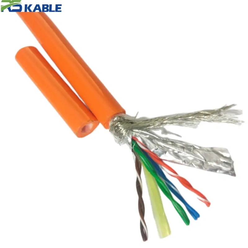
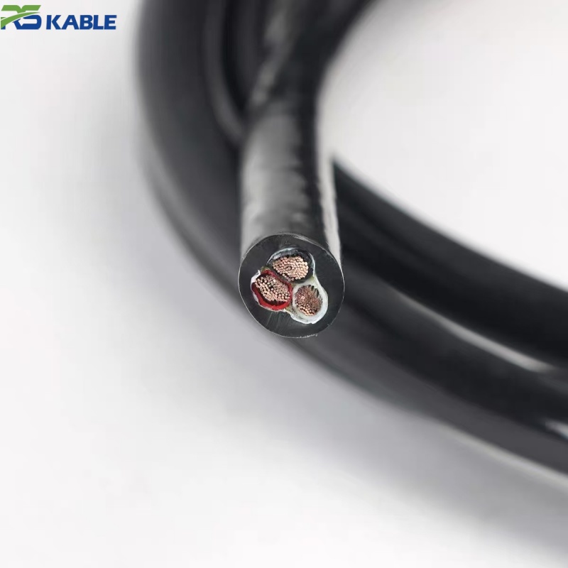
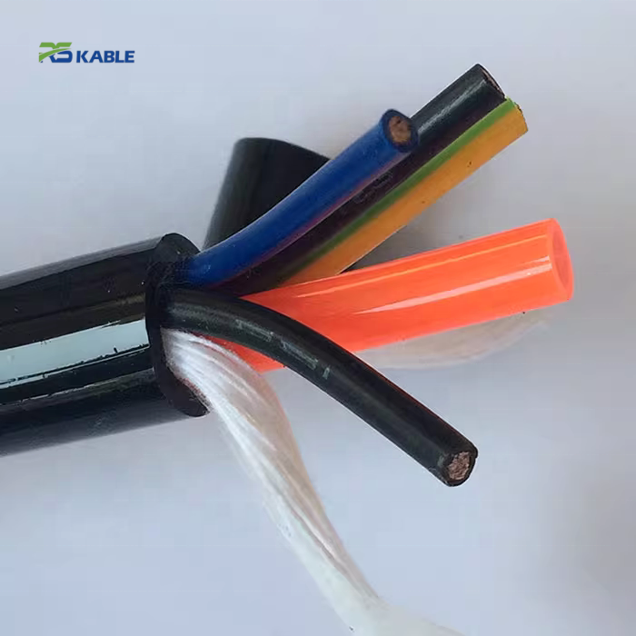
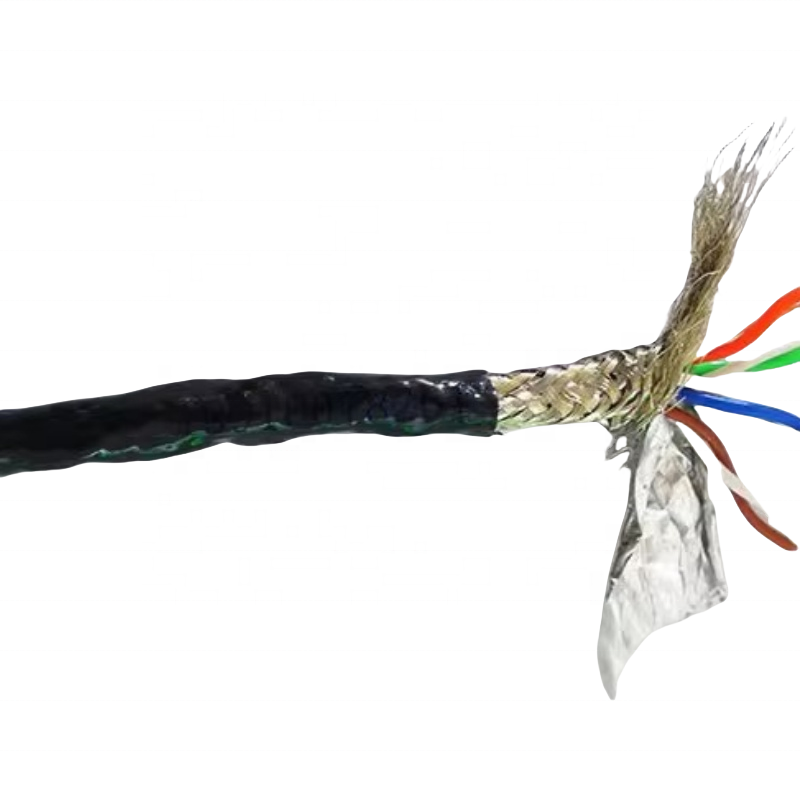
For observation-class vehicles, a heavy tether may reduce maneuverability even when its electrical performance is excellent. For work-class systems, mechanical loads, abrasion, hydrostatic pressure, fluid exposure, and repeated bending may dominate the construction. Review the available ROV cable options as a starting point, then specify the actual mission requirements.
Copper Power Conductors or a Hybrid Power-and-Fiber Tether?
Power conductors and optical fibers solve different problems. Copper carries electrical power and can carry lower-rate signals, while optical fiber provides high bandwidth and immunity to electromagnetic interference with negligible signal attenuation over typical ROV tether lengths. A hybrid cable can combine power conductors, fiber, control pairs, strength members, and buoyancy elements in one construction.
Adding fiber does not reduce the copper required for a given power duty, but it can separate high-speed communications from noisy power circuits and support cameras, sonar, and sensor data. The tradeoffs include termination complexity, minimum bend radius, fiber protection, connector choice, repair method, and cost. The correct hybrid design begins with a channel list and power budget, not simply a conductor count.
Practical ROV Cable Sizing Workflow
- Create a load schedule for every subsea device, including continuous, simultaneous, startup, and fault currents.
- Choose candidate transmission voltages and estimate conversion losses.
- Calculate current at the transmission voltage, including efficiency and design margin.
- Calculate loop resistance using the full current path and temperature-corrected resistance.
- Check voltage at the vehicle for every load case and source-voltage tolerance.
- Calculate I²R loss and confirm thermal performance in the deployed and reeled conditions.
- Check insulation, connector, penetrator, and protection ratings for normal voltage and transients.
- Evaluate diameter, drag, submerged weight, buoyancy, tensile load, bend radius, flex life, and termination.
- Prototype or test the complete power path under representative load before sea trials.
Engineers comparing failure modes may also find this article useful: why an ROV loses power before it reaches the seafloor. For a broader procurement overview, read the ROV cable buying guide.
Common ROV Cable Sizing Mistakes
- Using one-way resistance: A two-wire DC circuit needs outgoing-plus-return resistance.
- Sizing from average current: Peak simultaneous and startup loads often set the real requirement.
- Ignoring temperature: Warm copper has higher resistance and creates more voltage drop.
- Checking ampacity only: A thermally acceptable conductor may still starve the vehicle of voltage.
- Excluding connectors and slip rings: These components add resistance and may become local hot spots.
- Assuming the full source voltage is always available: Include supply tolerance, converter regulation, and protection-device drop.
- Adding copper without checking handling: Diameter, drag, weight, stiffness, and bend radius can compromise the mission.
- Applying DC equations to AC without adjustment: AC impedance, phase configuration, power factor, and harmonics require the appropriate model.
Information to Include in an ROV Cable Specification
A useful request for quotation should state:
- application and ROV type;
- one-way operating length and total supplied length;
- source voltage, AC/DC, frequency, and phase arrangement;
- continuous, maximum simultaneous, startup, and fault current;
- minimum acceptable voltage at the vehicle;
- number and size of power conductors;
- signal pairs, coaxial elements, or optical-fiber count and type;
- working depth or pressure, water type, and temperature range;
- required breaking strength and working tensile load;
- target weight in water and buoyancy behavior;
- static and dynamic bend-radius limits and flex-cycle expectations;
- jacket material, abrasion, oil, chemical, and UV exposure;
- reel, sheave, termination, connector, and penetrator details;
- applicable standards, inspection, testing, and documentation requirements.
Frequently Asked Questions
What is an acceptable voltage drop for an ROV cable?
There is no universal percentage. The acceptable drop is the difference between the lowest credible source voltage and the minimum voltage required by the vehicle, after reserving margin for converters, transients, temperature, and component tolerances. A percentage such as 3% or 5% can be an early target, but the equipment input range should control the final value.
Should I increase conductor size or transmission voltage?
Increasing conductor area reduces resistance without changing the electrical architecture, but it may make the tether larger, heavier, and less flexible. Increasing transmission voltage can reduce current and I²R loss, but it adds insulation, conversion, protection, and safety requirements. Compare both options at system level.
Does water cooling increase cable ampacity?
Deployment in water can improve heat transfer, but cable construction, depth, water movement, grouping, internal layers, and termination conditions still matter. The reeled portion may be the thermal bottleneck. Use qualification data for the complete tether rather than assuming unlimited cooling.
How do I calculate voltage drop for a three-phase ROV supply?
A common balanced three-phase approximation uses line current, line-to-line voltage, power factor, and cable impedance, with a square-root-of-three factor. However, long subsea cables and converter-fed loads can require a more complete model including reactance, capacitance, harmonics, and startup behavior. Consult the system electrical engineer and cable manufacturer.
Can a cable pass a continuity test and still cause ROV power problems?
Yes. A continuity test can confirm a complete circuit but does not prove sufficiently low resistance under load. Measure receiving-end voltage, current, conductor or termination temperature, and transient behavior at representative power.
Discuss Your ROV Power and Tether Requirements
Reliable subsea power starts with a complete set of electrical and mechanical inputs. Send us your tether length, transmission voltage, continuous and peak load, minimum vehicle voltage, depth, buoyancy target, tensile requirement, data channels, and termination details. Our team can review the requirements and discuss a suitable custom cable construction.
Contact RSTL Cable to request an ROV cable quotation.
Engineering note: The calculations above are simplified examples for preliminary selection. Final cable sizing, protection, insulation coordination, and system safety must be verified by qualified engineers against actual equipment data, applicable standards, and the complete installation.