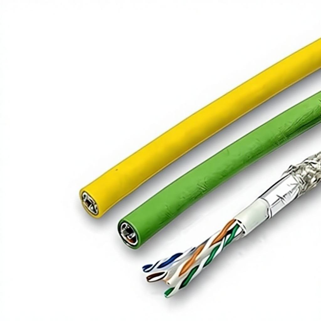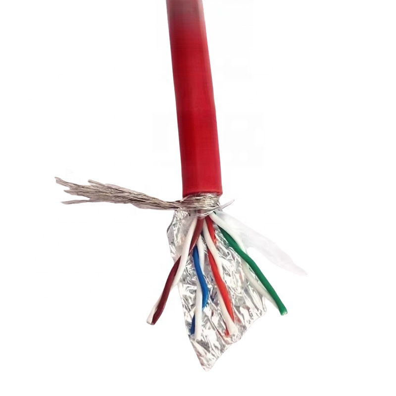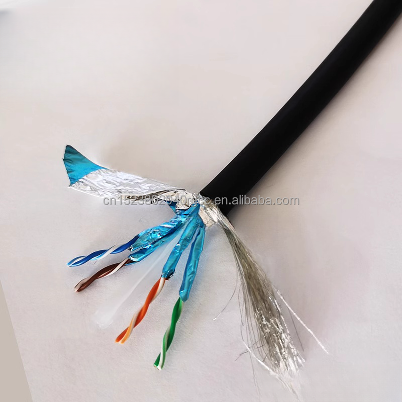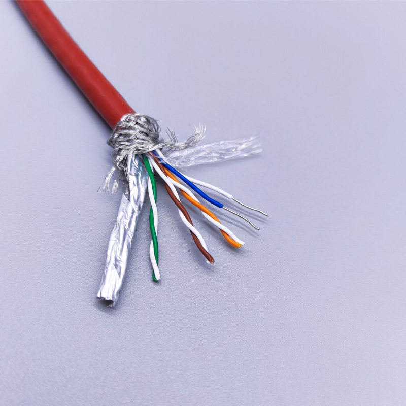



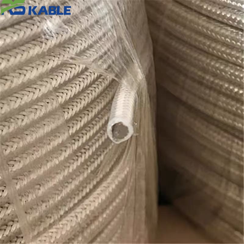
SFF75-5 Coaxial Cable | 200°C High Temperature Silver-Plated PTFE Video Cable
The SFF75-5 series is a 75Ω coaxial cable designed for video and RF signal transmission in high-temperature environments up to 200°C. Its silver-plated conductor and braided shield resist oxidation under sustained heat, while the solid PTFE dielectric holds impedance stable through prolonged thermal exposure. This cable is engineered for furnace monitoring, engine-bay wiring, and industrial high-heat installations where standard coaxial cable degrades long before the equipment’s service life ends.
Key benefits:
SFF75-5 Coaxial Cable: 200°C High-Temperature Silver-Plated PTFE Video Cable
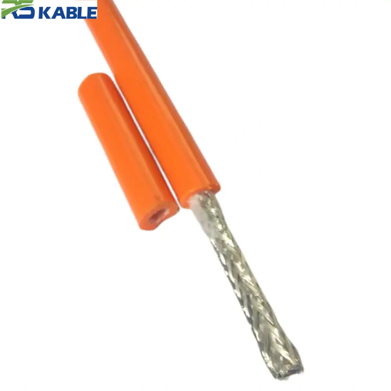
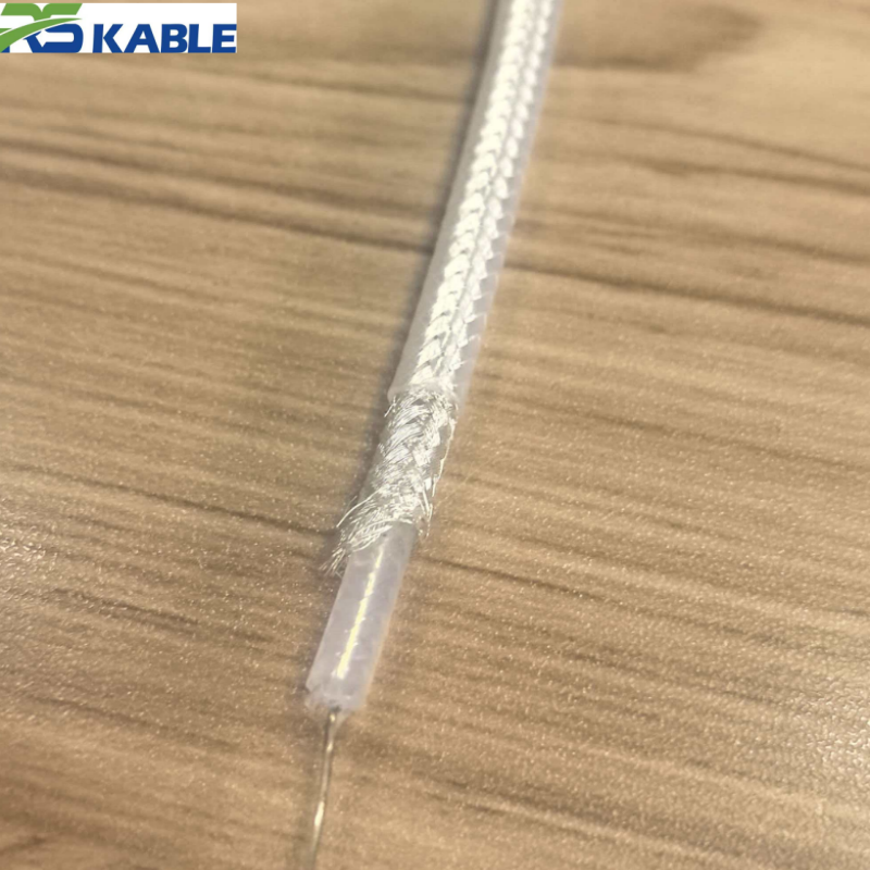
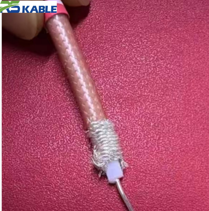
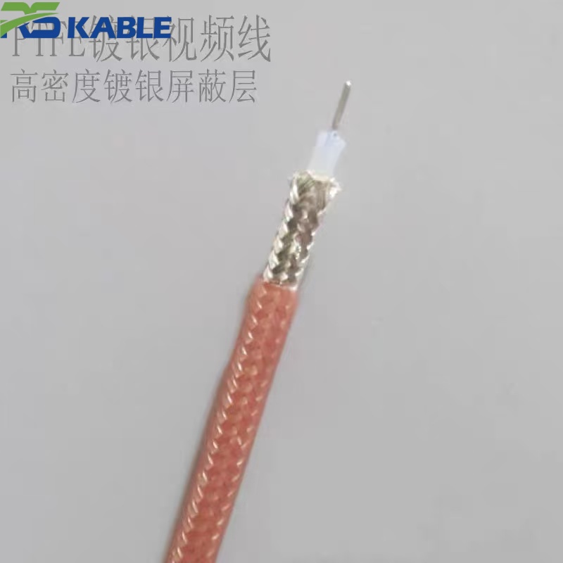
SFF75-5 is a 75Ω, solid-PTFE-dielectric coaxial cable built around a silver-plated conductor and braided shield. It is specified for video and RF circuits that must keep operating where standard 75Ω coax cannot — inside furnace enclosures, engine bays, boiler rooms, and other locations where ambient or radiant heat stays in the 150–200°C range for extended periods. The construction follows the general dielectric-diameter naming convention used across the SFF/SYV coaxial families (the “-5” denotes a nominal 4.8 mm PTFE dielectric core), and the electrical figures below are typical values for that dielectric size rather than marketing estimates.
Key Specifications at a Glance
| Parameter | Typical Value |
|---|---|
| Impedance | 75 Ω ± 3 Ω |
| Inner conductor | Silver-plated copper-clad steel, 0.72 mm solid |
| Dielectric | Solid PTFE, 4.8 mm nominal OD |
| Shield | Silver-plated copper braid, ≥90% coverage |
| Jacket | PTFE tape + FEP extrusion |
| Overall OD | 7.2 mm ± 0.3 mm |
| Continuous temperature rating | -65°C to +200°C |
| Short-term peak (PTFE limit) | up to 260°C, non-continuous |
| Attenuation @ 100 MHz | ≈ 5.4 dB/100 m |
| Attenuation @ 1 GHz | ≈ 19 dB/100 m |
| VSWR (DC–3 GHz) | ≤ 1.3 |
| Capacitance | ≈ 53 pF/m |
| Velocity of propagation | ≈ 69% |
| Voltage rating | 1500 V DC |
| Minimum bend radius | 10× OD static, 20× OD dynamic |
| Approx. weight | 55 g/m |
Figures are typical values for the SFF75-5 dielectric size under laboratory reference conditions. Actual batch data may vary within standard manufacturing tolerance and should be confirmed against the shipment-specific test report before final circuit design.
Applicable Standards and References
The construction is designed to align with the general requirements of:
- GB/T 17737 (China) — series covering RF and coaxial communication cables, dimensional and electrical test methods
- MIL-DTL-17 (US) — coaxial cable family specification widely referenced for silver-plated, PTFE-dielectric constructions in high-temperature and military-adjacent use
- IEC 61196 — international series for coaxial communication cables, sectional specifications for RF cable
These references define the test methodology and tolerance framework the cable is built to satisfy; they are not a claim of formal certification unless a specific certificate is issued for a given order.
Material and Construction Rationale
The three failure modes most often reported in 75Ω coax operating above 150°C are: (1) conductor oxidation raising DC resistance and attenuation over time, (2) dielectric creep or softening that shifts impedance and increases VSWR, and (3) shield-braid oxidation that lowers shielding effectiveness before the jacket shows any visible damage.
Silver has roughly 6% lower resistivity than copper at 20°C and, more importantly for this application, forms a stable oxide layer that does not significantly increase contact or surface resistance at sustained high temperature — bare copper or tin-plated copper does not have the same stability at 200°C. Solid PTFE is used as the dielectric because its softening point is well above the cable’s continuous rating, so the impedance-critical dielectric geometry does not deform under sustained heat the way polyethylene or PVC-based dielectrics would. The braid uses the same silver-plated copper as the inner conductor for the same oxidation-resistance reason, since a shield that degrades faster than the dielectric will limit real-world service life regardless of how the core is built.
Electrical Performance
| Frequency | Typical Attenuation (dB/100 m) | Typical VSWR |
|---|---|---|
| 10 MHz | 1.8 | 1.15 |
| 100 MHz | 5.4 | 1.20 |
| 500 MHz | 11.6 | 1.25 |
| 1 GHz | 19.0 | 1.30 |
| 3 GHz | 34.5 | 1.35 |
Insulation resistance is typically ≥ 5,000 MΩ·km at 500 V DC under reference conditions. These values assume a straight, unstressed run at 20°C; attenuation increases modestly with sustained temperature rise and should be de-rated using the project’s actual thermal profile for precision RF work.
Mechanical and Thermal Performance
| Test Condition | Typical Result |
|---|---|
| 200°C, 1,000 hours continuous soak | No jacket cracking, impedance shift < 2Ω |
| Thermal cycling, -40°C to 200°C, 100 cycles | No shield delamination observed |
| Static bend at 10× OD, 200°C | No dielectric deformation |
| Braid coverage after 500-hour 200°C soak | Coverage retained ≥ 88% (from ≥90% initial) |
These are typical qualification-style results for this construction class rather than guaranteed values for every production lot; a lot-specific test report should be requested for safety-critical or long-term unattended installations.
Field Performance Note
In a representative industrial retrofit — a ceramics kiln monitoring line previously wired with PVC-jacketed 75Ω coax — cable-related signal loss was reported roughly every 60–90 days, generally traced to jacket hardening and cracking near the kiln wall penetration. After switching to a silver-plated PTFE construction of this type, the reported interval between cable-related service calls extended to over a year in the same routing position. This is a single illustrative field pattern rather than a controlled study, and results will vary with kiln temperature profile, routing distance from the heat source, and mechanical wear at the penetration point.
Recommended Use vs. Conditions Requiring Engineering Review
| Recommended for | Requires engineering review before use |
|---|---|
| Static or low-flex CCTV runs in furnace and kiln enclosures | Continuous dynamic flexing at sustained 200°C |
| Engine-bay or nacelle video/RF runs with sustained radiant heat | High-power RF transmission (above standard low-power video/RF levels) |
| Boiler room and power-plant monitoring wiring | Direct flame or molten-material contact |
| Downhole or process-industry RF links exposed to elevated ambient heat | GHz-range precision RF where insertion-loss budget is tight |
| Nuclear-facility or defense-sector video runs specified to MIL-DTL-17-adjacent requirements | Combined cryogenic-to-high-temperature cycling in one duty cycle |
Benchmarking Against Standard 75Ω Coax
| Metric | SFF75-5 (silver-plated PTFE) | Standard RG-59/RG-6 class (copper/PVC) |
|---|---|---|
| Continuous temperature ceiling | 200°C | Typically 60–80°C |
| Conductor oxidation resistance at sustained heat | High (silver oxide layer is stable) | Low above ~100°C |
| Impedance drift after prolonged heat exposure | Typically < 2Ω | Often > 5Ω, dielectric-dependent |
| Reported field service interval in heated enclosures* | Commonly 12+ months | Commonly 2–4 months |
| Relative unit cost | Higher (silver plating, PTFE) | Lower |
*Service-interval figures are drawn from the field pattern described above and general industry reporting for this cable class; they are not a guaranteed replacement schedule for every installation.
Specification Checklist for Ordering
| If your application involves… | Then specify… |
|---|---|
| Sustained ambient/radiant heat above 150°C | Continuous temperature rating and jacket type (PTFE vs FEP) |
| High-EMI equipment nearby (VFDs, induction heaters) | Double-braid or braid-plus-foil shielding |
| A run length that pushes signal budget | Attenuation figures at your actual operating frequency, not just DC resistance |
| A tight bend near a wall or panel penetration | Confirmed minimum bend radius at your actual installation temperature |
| A safety-critical or unattended installation | A lot-specific test report referencing the standard you are designing to (GB/T 17737, MIL-DTL-17, or IEC 61196) |
| Non-standard termination | Connector type and whether a high-temperature connector boot/adapter is required |
Customization Scope
| Element | Options |
|---|---|
| Conductor size | Adjusted for longer runs or lower attenuation requirements |
| Shield structure | Single braid, double braid, braid + foil |
| Jacket | PTFE, FEP, or project-specified high-temperature compound |
| Termination | BNC, N-type, or project-specific connector |
| Marking and length | Custom print marking, cut length or reel supply |
Common Specification Questions
Does the 200°C rating apply to the jacket, the dielectric, or the whole assembly? It is the continuous rating for the complete assembly under the qualification testing summarized above. PTFE itself tolerates brief excursions above that figure, but 200°C is the number to design continuous circuits against.
Why is attenuation given as a range across frequencies instead of one number? Attenuation in any coaxial cable rises with frequency; a single number would misrepresent performance for anything other than the exact frequency it was measured at. The table above lets a designer read the figure at the frequency actually in use.
Is silver plating necessary if the installation only reaches 120–150°C? At the lower end of that range, a well-made tin-plated or bare-copper conductor may be adequate; the oxidation-resistance advantage of silver becomes more decisive as sustained temperature approaches 180–200°C. This is worth confirming against the specific duty cycle before over- or under-specifying.
Can this cable be flexed repeatedly while hot? Not as a default recommendation. The construction is qualified for static or limited-flex routing; continuous dynamic flexing at sustained high temperature is listed above as a condition requiring separate engineering review, since repeated flex at elevated temperature is a different fatigue mode than static thermal soak.
How does this compare to a mineral-insulated or armored high-temperature cable? Mineral-insulated cable generally tolerates higher absolute temperatures but is rigid and harder to route; this PTFE construction trades some temperature ceiling for flexibility and standard coaxial termination compatibility. The right choice depends on whether the installation constraint is routing flexibility or absolute temperature ceiling.
Technical content reviewed by the cable engineering team prior to publication. Figures represent typical performance for this construction class; request a shipment-specific test report for safety-critical designs.