


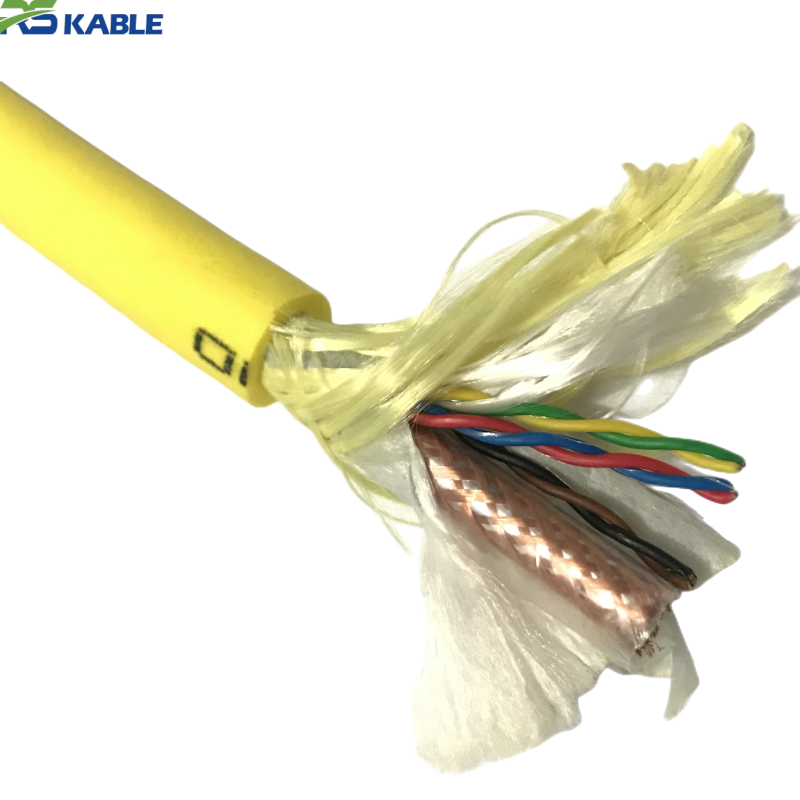
RG59 Coaxial Underwater Video Cable with 14×22AWG Power Conductors | ROV Camera Cable
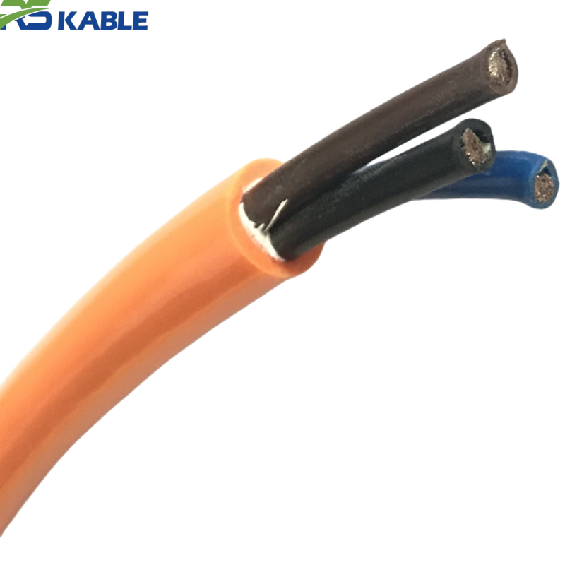
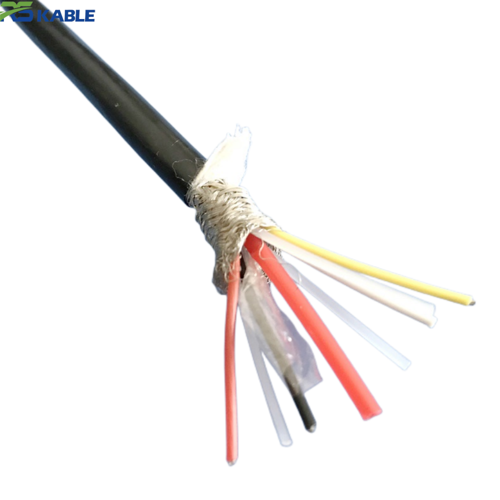
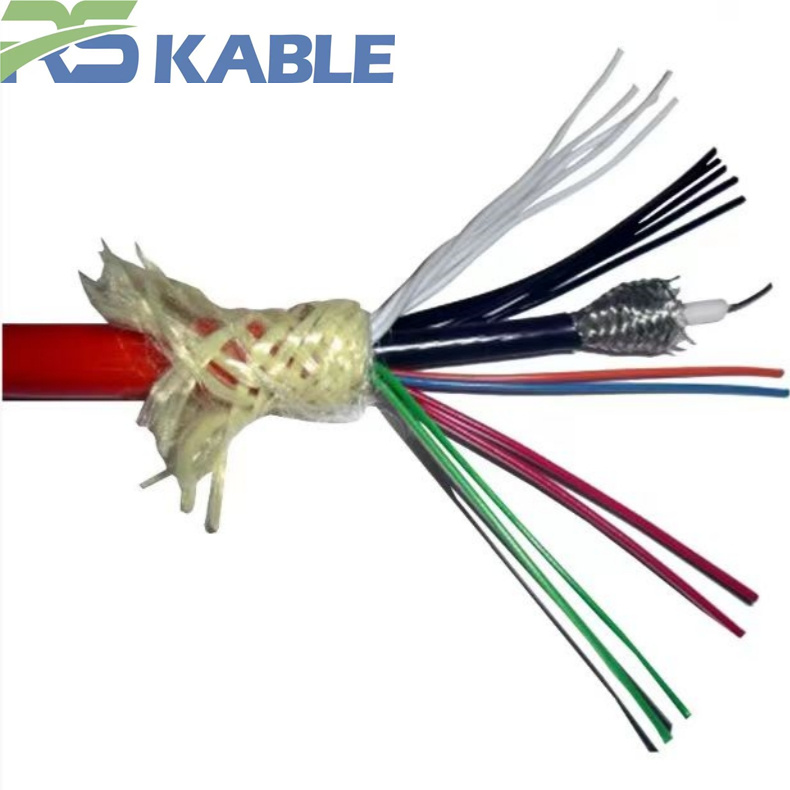
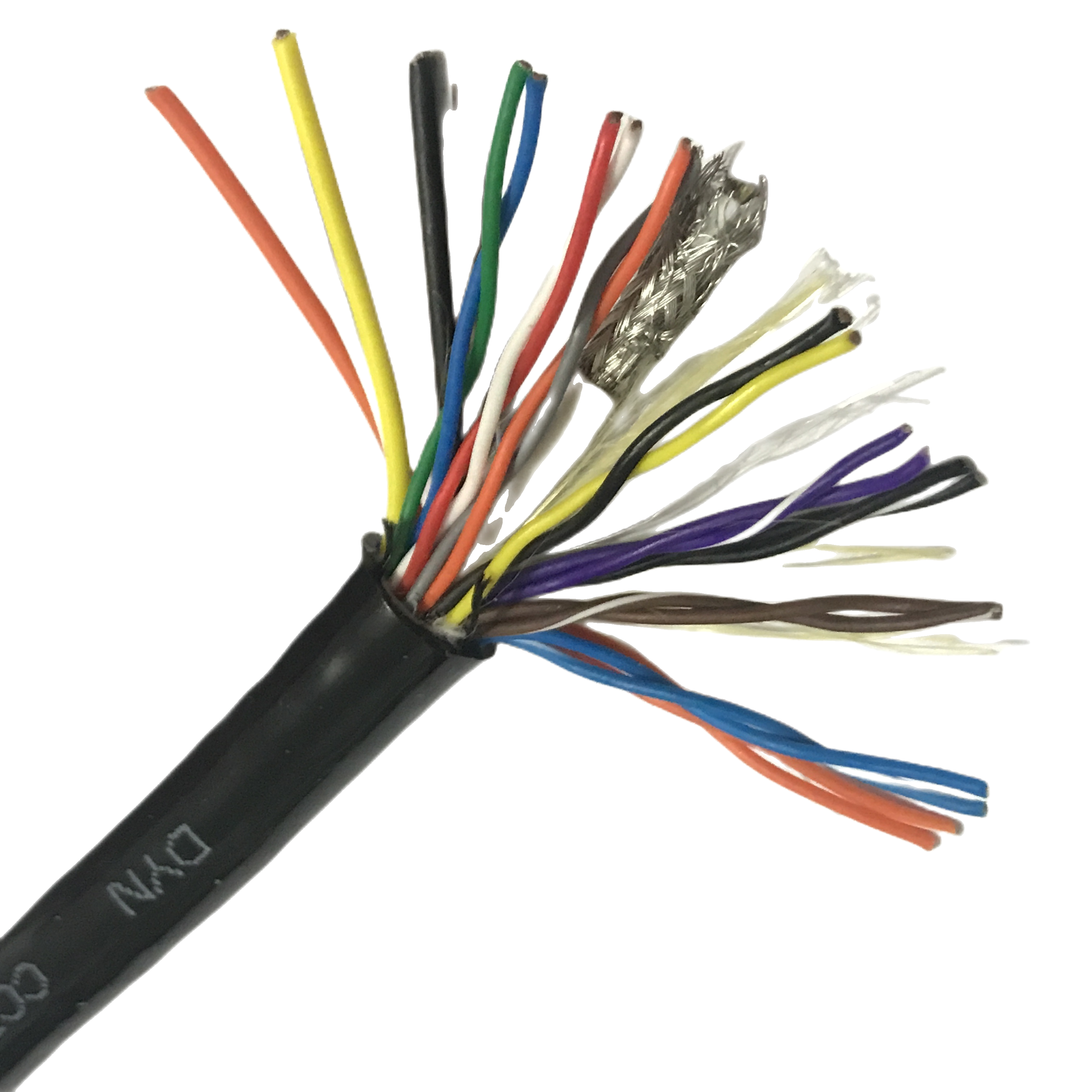
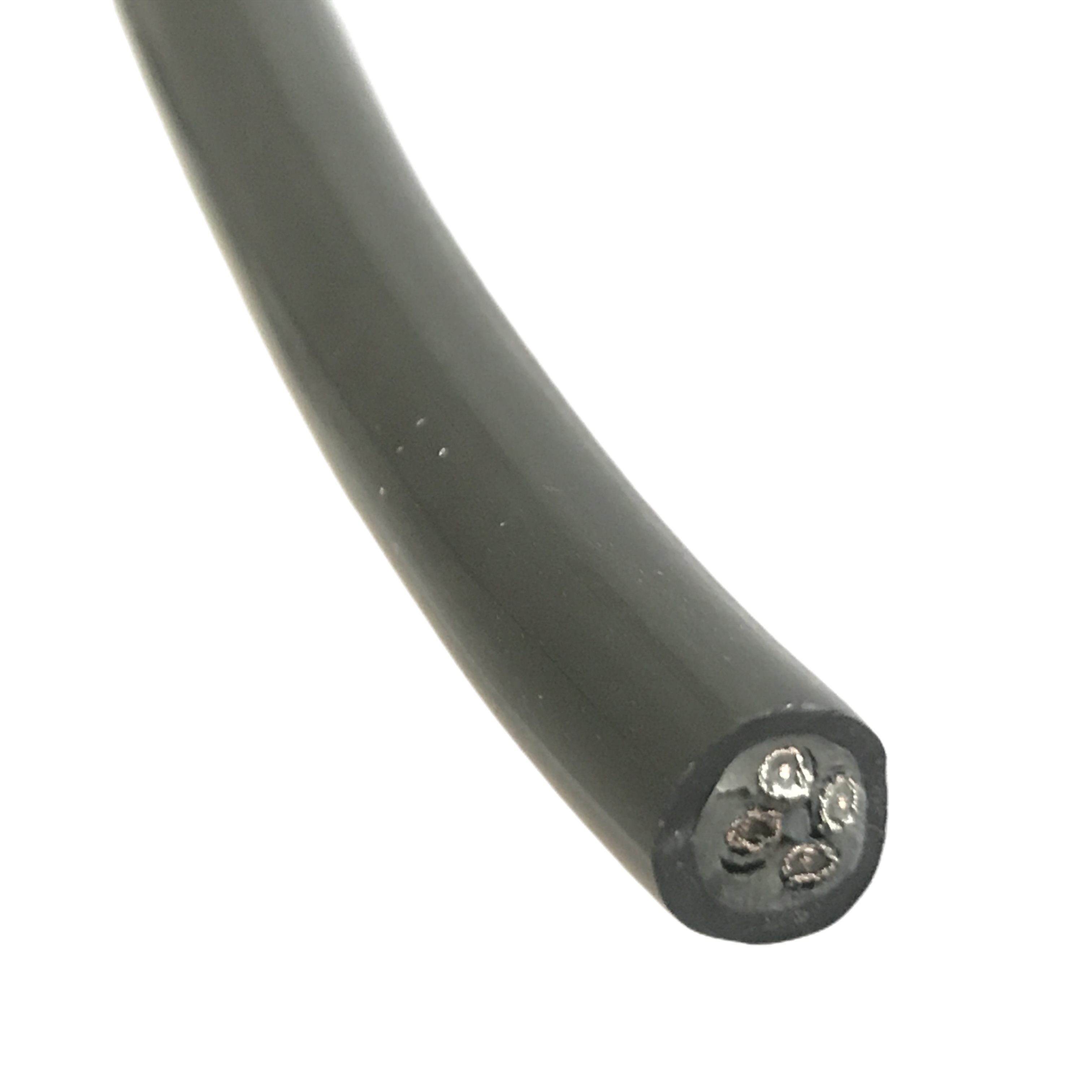
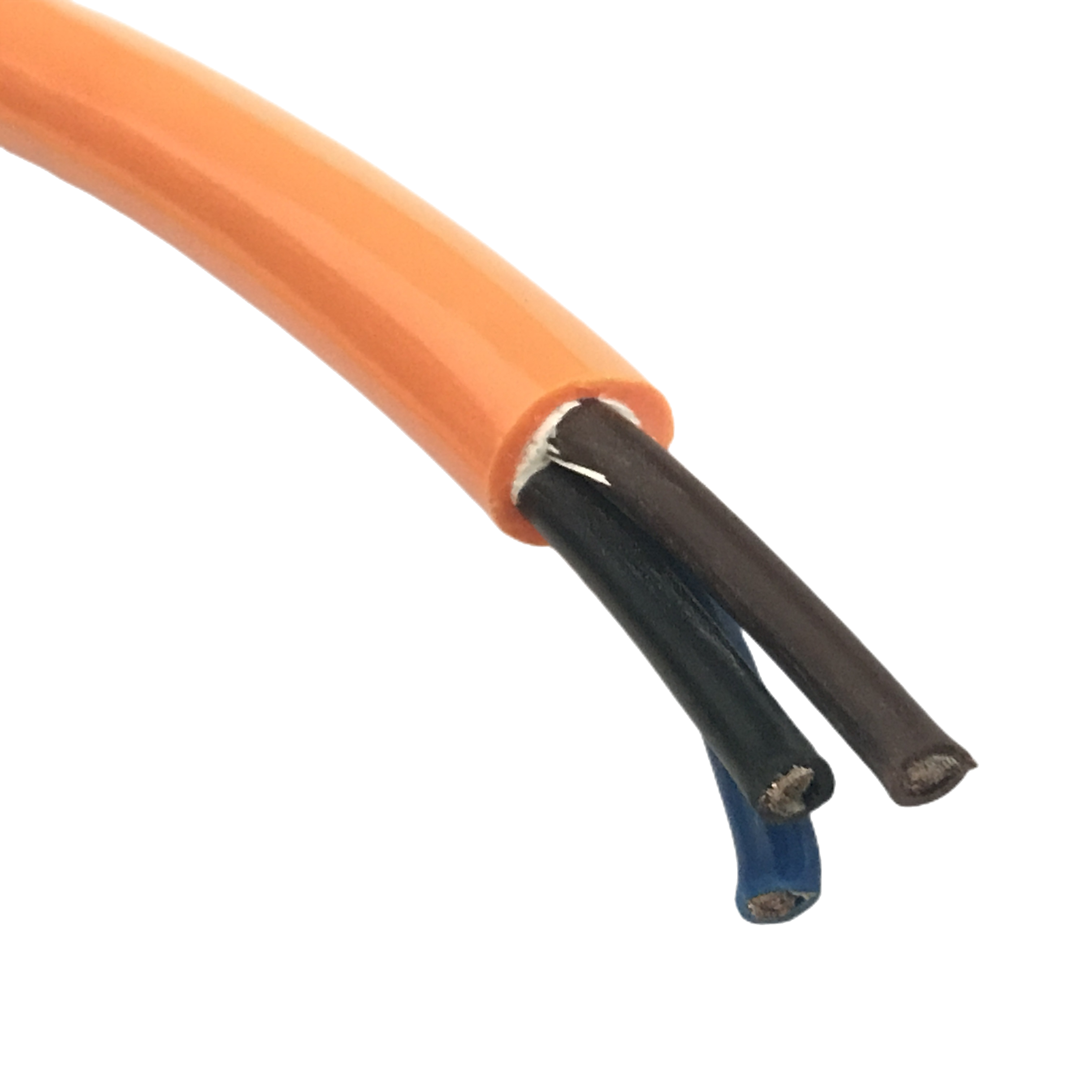
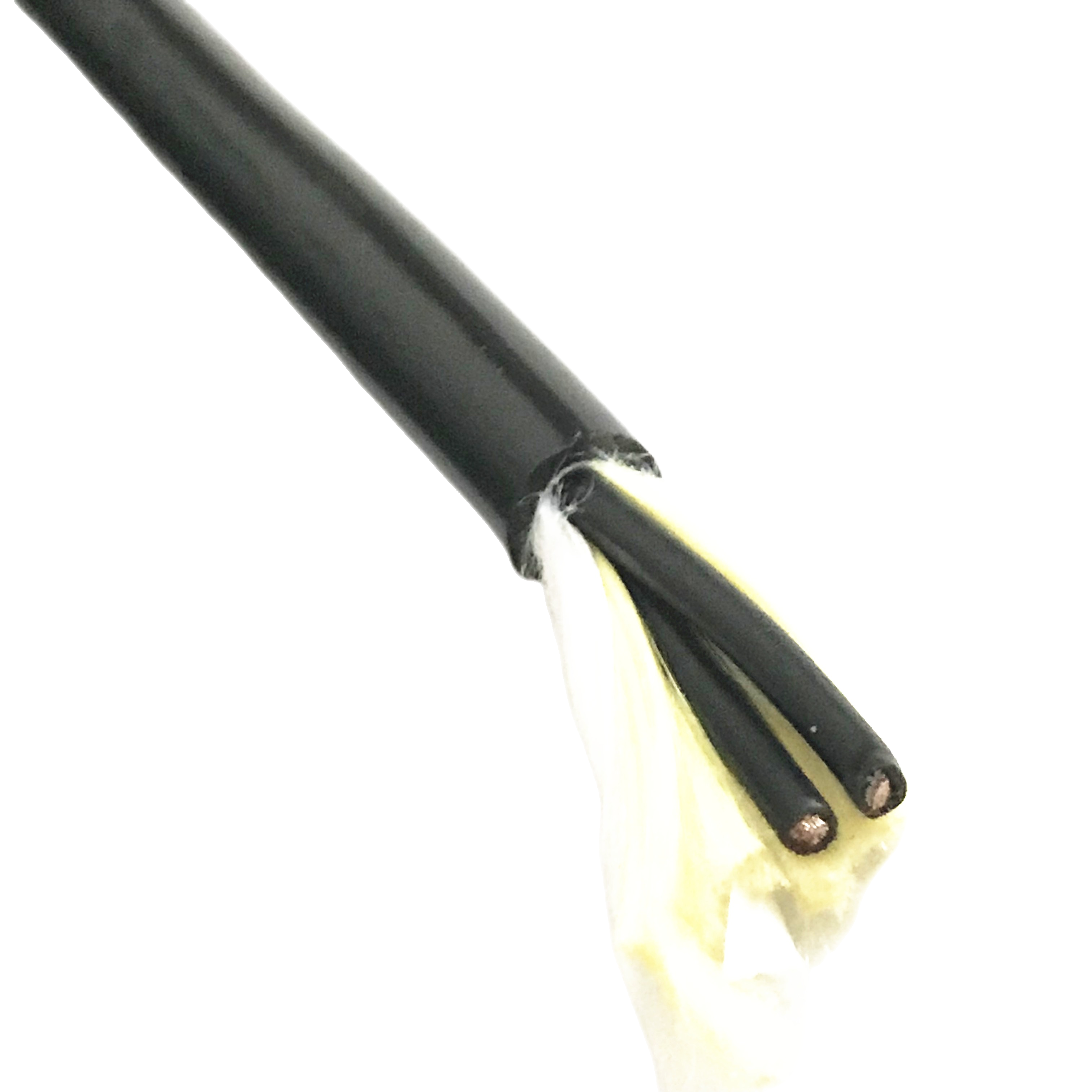
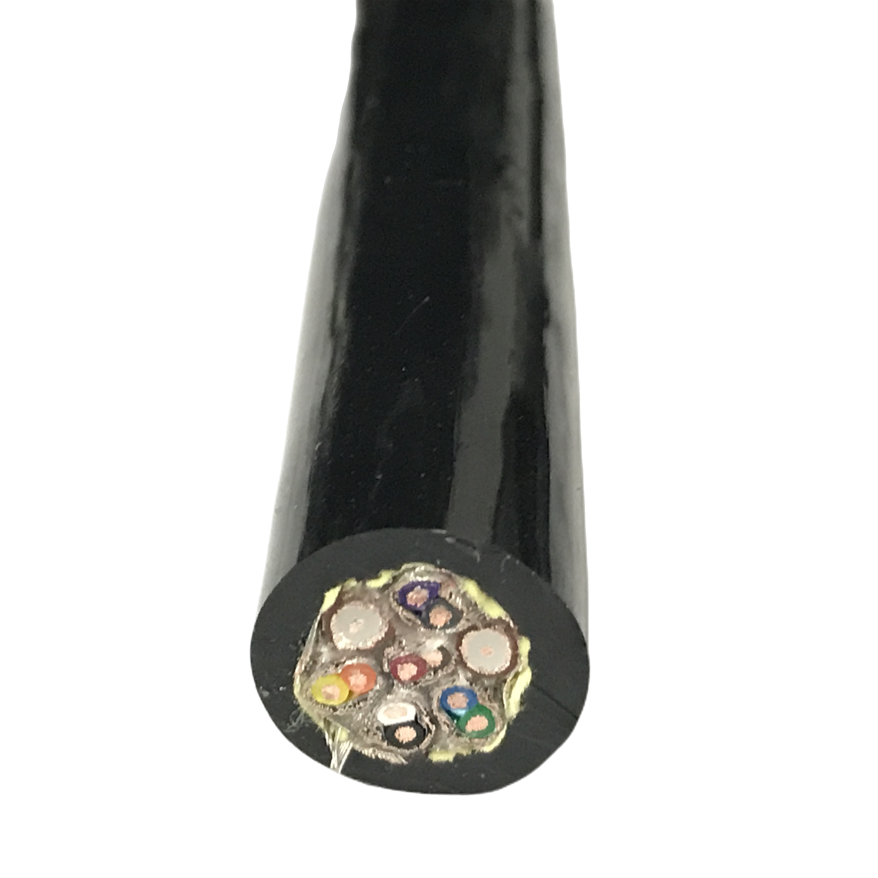
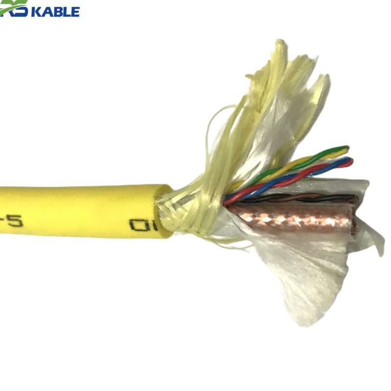
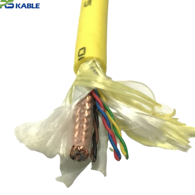
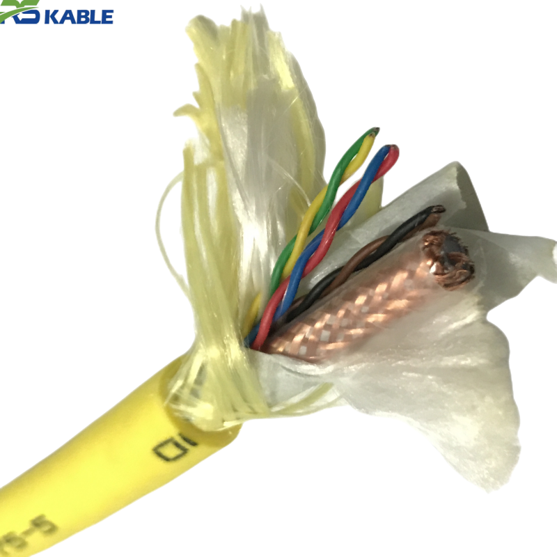
The RST-RCC series combines an RG59 video coax with 14×22AWG power conductors in a single waterproof tether, built for ROV and underwater camera systems with multiple independent power circuits. Its engineered conductor placement minimizes noise coupling from pan-tilt motor drives onto the video signal, while the waterproof PU jacket and aramid strength member handle continuous submersion and deployment loads.
Key benefits:
RG59 Coaxial Underwater Video Cable with 14×22AWG Power Conductors
Specifying this cable correctly starts with two separate budgets: how far the composite video signal can run before image quality drops below what the monitoring equipment needs, and how the fourteen 22AWG conductors get allocated across the camera housing’s independent circuits. Both are addressed with real numbers below, ahead of the general construction and ordering detail.
Video Channel Performance
| Metric | Typical Value |
|---|---|
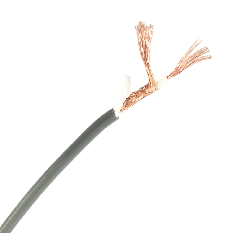
| Coax impedance | 75Ω (RG59/U-equivalent) |
| Attenuation at 1 MHz | ≈ 1.8 dB/100 m |
| Attenuation at 5 MHz | ≈ 4.5 dB/100 m |
| Recommended max run, no inline amplification | ≈ 300 m for acceptable composite image quality |
| Recommended max run, with inline video amplifier | ≈ 600 m |
| Signal degradation pattern | Gradual loss of high-frequency detail (softened image) rather than abrupt cutoff |
These figures reflect typical composite video behavior over RG59 at the higher end of the analog video baseband, where fine detail is carried; actual acceptable distance depends on the receiving monitor or recorder’s sensitivity, and should be confirmed against the exact equipment before committing to a run beyond about 250 m without a booster.
Power Circuit Allocation Map
The fourteen 22AWG conductors are grouped as seven functional pairs, matching how most multi-function camera housings actually divide their circuits:
| Conductor Pair | Typical Function | Current Capacity (22AWG, short run) |
|---|---|---|
| Pair 1–2 | Camera electronics power | Up to ≈ 3 A continuous |
| Pair 3–4 | LED lighting array power | Up to ≈ 3 A continuous |
| Pair 5–6 | Pan drive motor | Up to ≈ 2 A continuous (duty-cycle dependent) |
| Pair 7–8 | Tilt drive motor | Up to ≈ 2 A continuous (duty-cycle dependent) |
| Pair 9–10 | Pan/tilt position feedback signal | Signal-level, not power-rated |
| Pair 11–12 | Auxiliary/spare circuit | Up to ≈ 3 A continuous |
| Pair 13–14 | Common/ground return | Sized to match the paired circuit’s load |
22AWG current capacity drops with run length due to voltage drop rather than conductor heating on most camera-housing loads, so a 60 m tether carrying 3 A on a 12 V circuit should be checked for voltage drop at the housing, not just against the conductor’s short-run current rating shown above.
Mechanical and Environmental Data
| Test | Typical Result |
|---|---|
| Insulation resistance | ≥ 100 MΩ·km at 500 V DC |
| Tensile breaking load | ≈ 60 kgf, aramid-reinforced |
| Minimum bend radius | 8× overall diameter |
| Depth rating (standard) | To 200 m; greater depth available as a project-specific jacket/pressure review |
| Jacket abrasion | No breach at rated reciprocating-abrasion cycle count for this jacket class |
| Operating temperature | -10°C to 60°C |
Figures represent typical qualification-level results for this construction; a shipment-specific certificate should be requested where the cable will operate beyond the standard 200 m depth class or in a safety-relevant deployment.
How the Cable Is Built
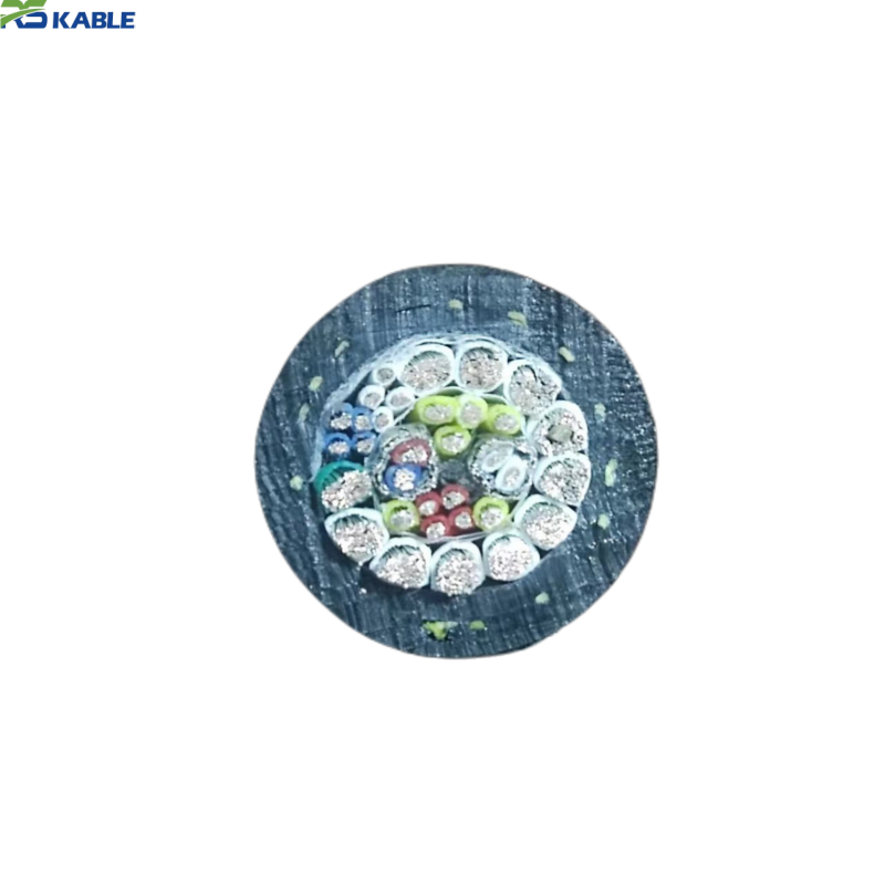
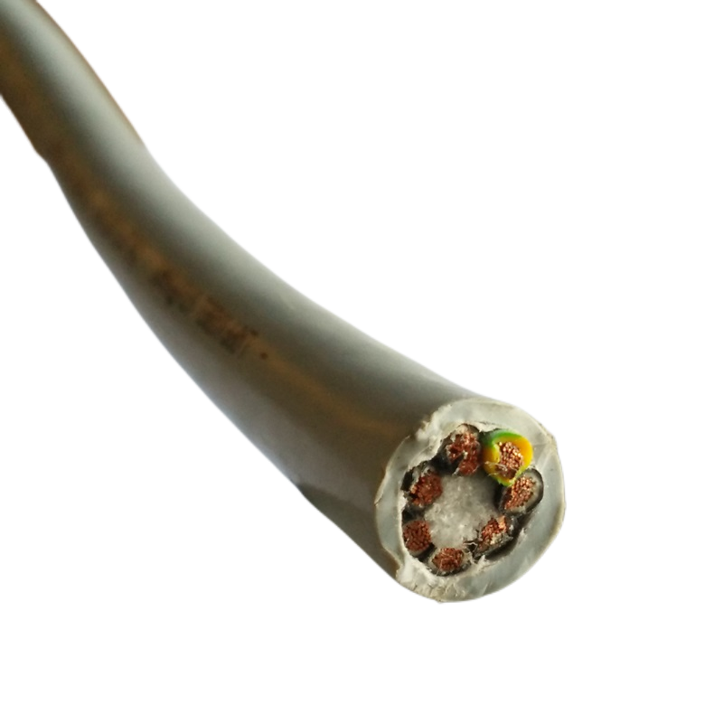
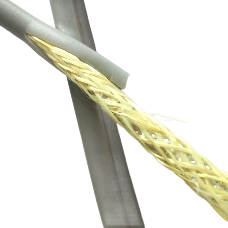
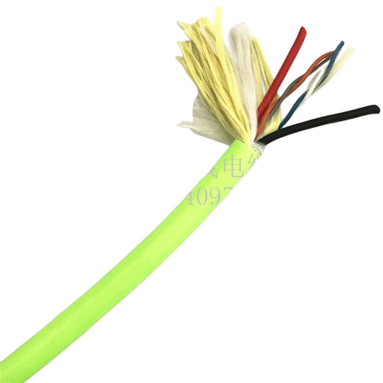
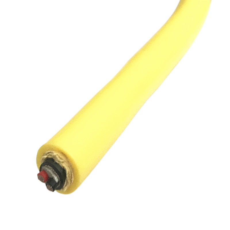
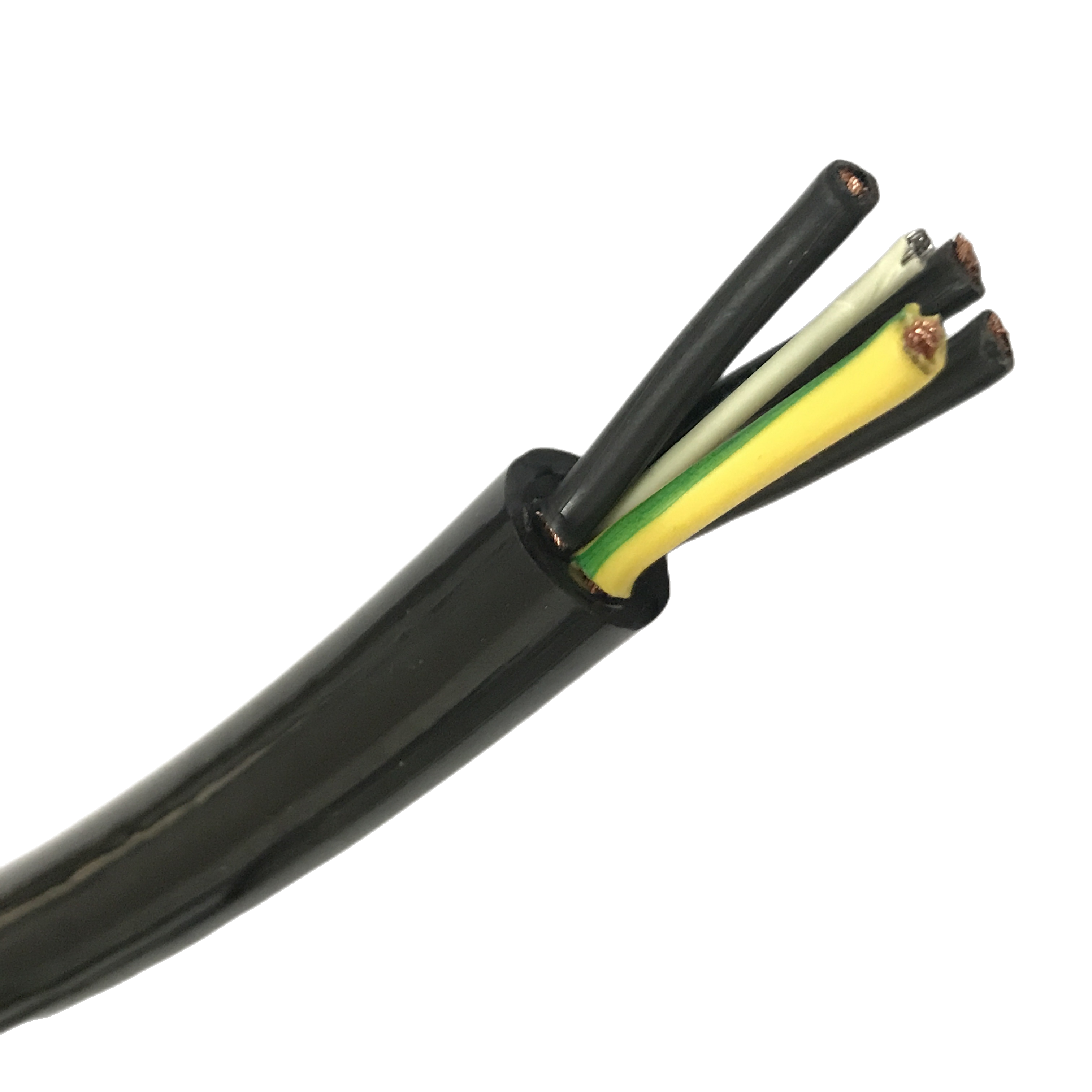
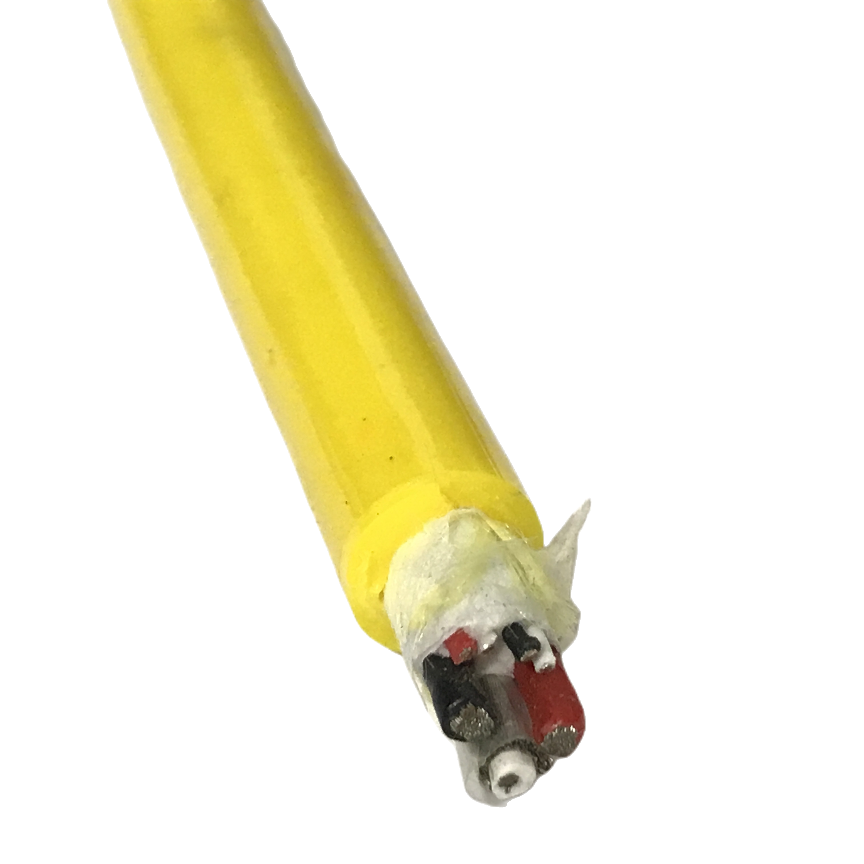
The RG59 coax and the fourteen power conductors are cabled together with the power pairs positioned away from the coax core, since the pan and tilt motor pairs are the circuits most likely to induce noise onto the adjacent video signal. An aramid yarn strength member runs through the bundle to carry tensile load during deployment so that neither the coax nor the smaller power conductors take that stress directly. The outer polyurethane jacket is a single continuous waterproof layer over the full bundle — there is no secondary jacket around the coax or power group individually, which keeps overall diameter down but means the shielding decision (standard vs. overall-shielded variant) has to be made for the whole assembly rather than per element.
Standards Framework
The coaxial element follows the general dimensional and electrical conventions historically associated with the RG59/U designation under the MIL-C-17 coaxial cable family, adapted here into a multi-conductor waterproof composite rather than a standalone coax product. Conductor insulation and outer jacket material qualification follow the general testing philosophy of IEC 60092-350 for offshore and shipboard cable materials. These references describe the engineering framework the construction is built against rather than a claim of formal type approval; a project-specific certificate should be requested where a client specification requires one.
Field Pattern: Aquaculture Net-Pen Camera Fleet
An aquaculture operator running pan-tilt inspection cameras across multiple net pens reported intermittent video dropout on tethers routed past pan/tilt motor housings when using generic bundled coax-and-power cable sourced separately for video and power. After switching to a single composite cable with the shielded power-bundle variant, reported dropout incidents on runs in the 150–250 m range were substantially reduced, and the operator noted fewer tangling incidents during net-pen-to-net-pen redeployment since each camera now trails a single tether instead of two. This reflects one operator’s reported field experience rather than a controlled comparative trial, and results depend on the specific camera hardware, motor duty cycle, and monitor equipment in use.
Composite Cable vs Separate Coax and Power Runs
| Metric | Composite RG59 + 14×22AWG Cable | Separate Coax and Power Cables |
|---|---|---|
| Lines at the deployment point | One | Two or more |
| Reported tangling incidents during redeployment* | Lower | Higher |
| Noise coupling control | Engineered into conductor placement | Depends on installer’s routing choices |
| Strain relief points | One | One per cable |
| Best use | Multi-circuit camera housings, frequent redeployment | Simple single-power links where bundling adds little |
*Based on the field pattern above and general reporting for this cable class; not a guaranteed outcome for every installation.
Ordering Matrix
| If your installation involves… | Then specify… |
|---|---|
| A run longer than ≈250 m | Confirm whether an inline video amplifier will be used, since this affects acceptable cable length |
| Pan/tilt motors near the video line | The shielded power-bundle variant |
| More or fewer than seven functional circuits | A custom conductor count rather than the standard 14-conductor configuration |
| Deployment beyond 200 m depth | A project-specific jacket and pressure review before ordering |
| Hand deployment by a diver vs. winch deployment | Confirm expected tensile load so the aramid reinforcement is sized correctly |
Technical Notes
Does image quality actually fail at exactly 300 meters, or is that a hard limit? No — composite video over RG59 degrades gradually, losing fine detail first rather than cutting out abruptly. 300 m is a practical guideline for acceptable quality on typical monitoring equipment, not a hard cutoff; some setups tolerate longer runs and some need a booster sooner, depending on receiver sensitivity.
Why are the pan and tilt motor pairs kept in specific positions rather than anywhere in the bundle? Motor drive circuits, especially during direction changes, generate switching noise that can couple onto adjacent conductors. Keeping those pairs away from the coax core and offering an overall shield on the power bundle both address this at the construction stage rather than leaving it to installation routing.
Can the same 14-conductor configuration cover a camera housing with more than seven functions? Not directly — the standard allocation covers seven functional pairs. A housing with more independent circuits needs a custom conductor count specified at the ordering stage rather than trying to double up functions on the standard configuration.
What happens to the 22AWG current rating on a long tether? The current ratings above apply to short runs; on longer tethers, voltage drop at the housing becomes the limiting factor before conductor heating does, particularly on higher-current circuits like camera or lighting power. This should be checked against the actual run length and load rather than the short-run figure alone.
Is the 200 m depth rating adjustable for deeper installations? Yes, but not as a simple extension of the standard specification — deeper deployment requires a project-specific review of jacket thickness and pressure handling rather than assuming the standard 200 m construction scales linearly with added jacket material.
Technical content reviewed by the cable engineering team prior to publication. Figures represent typical performance for this construction and testing methodology; request a shipment-specific certificate for deployments beyond the standard depth class or safety-relevant installations.