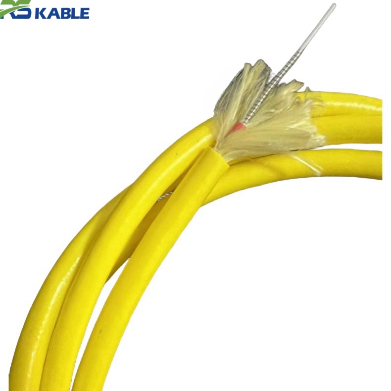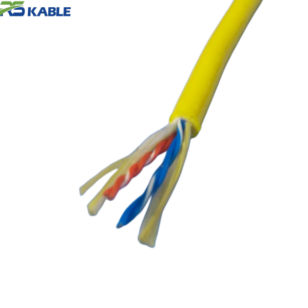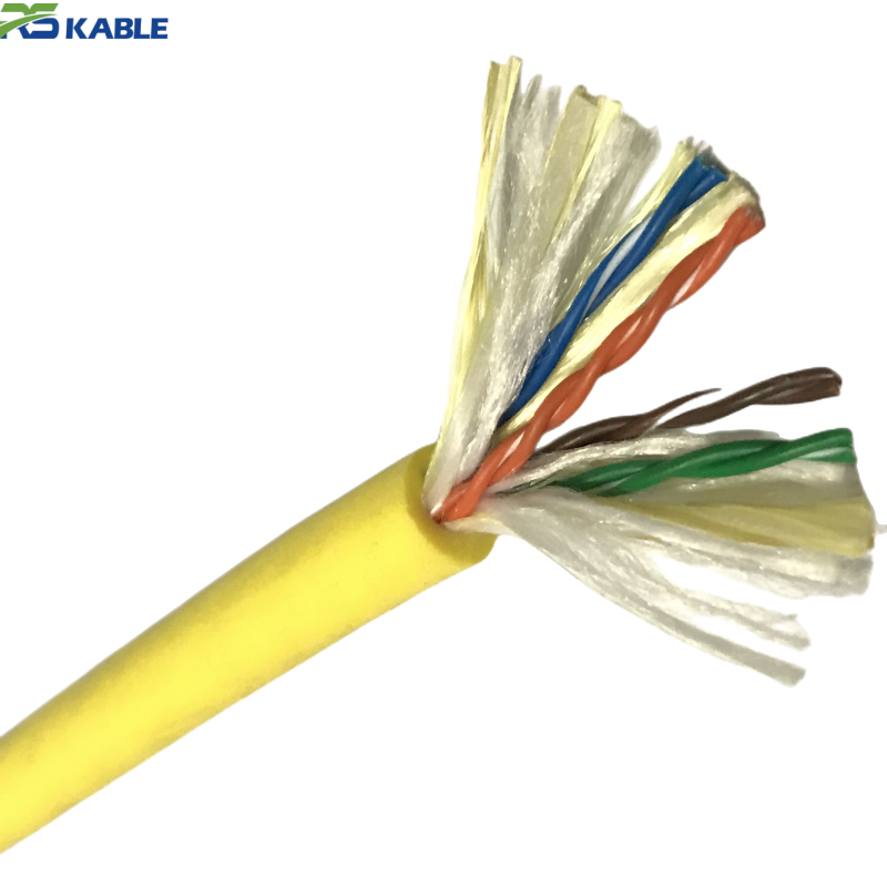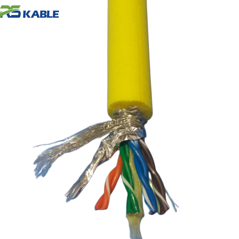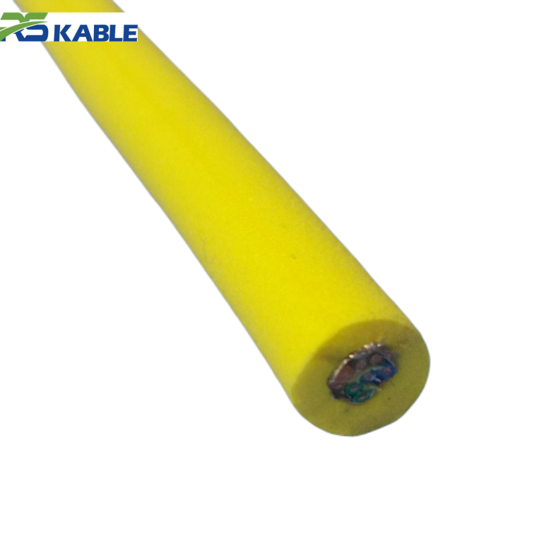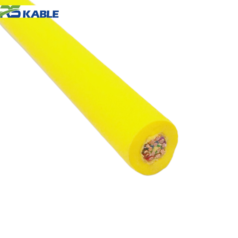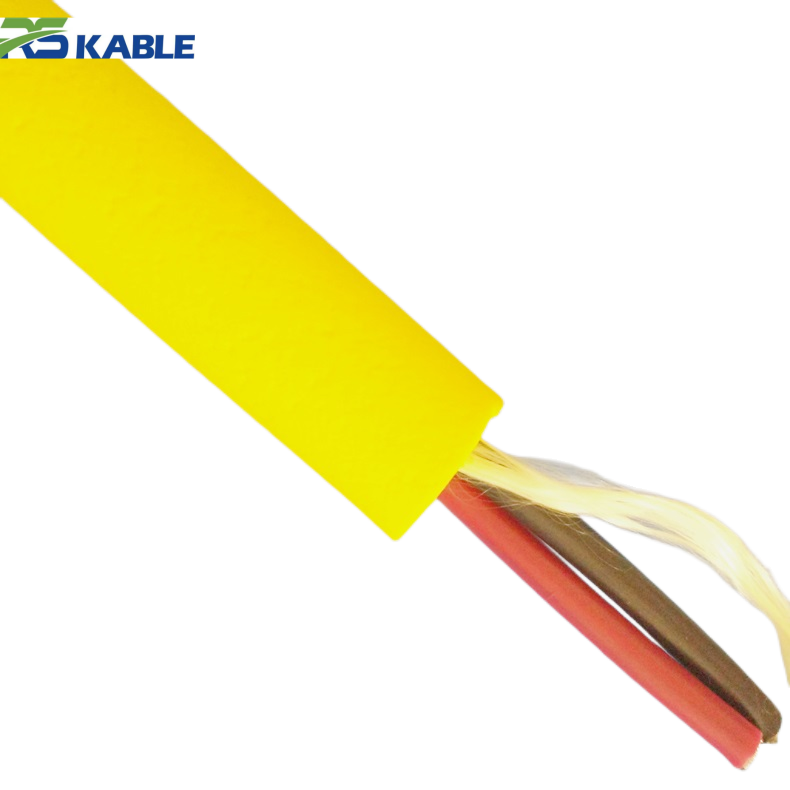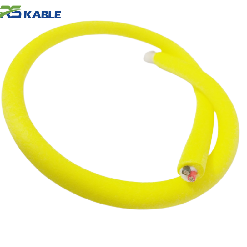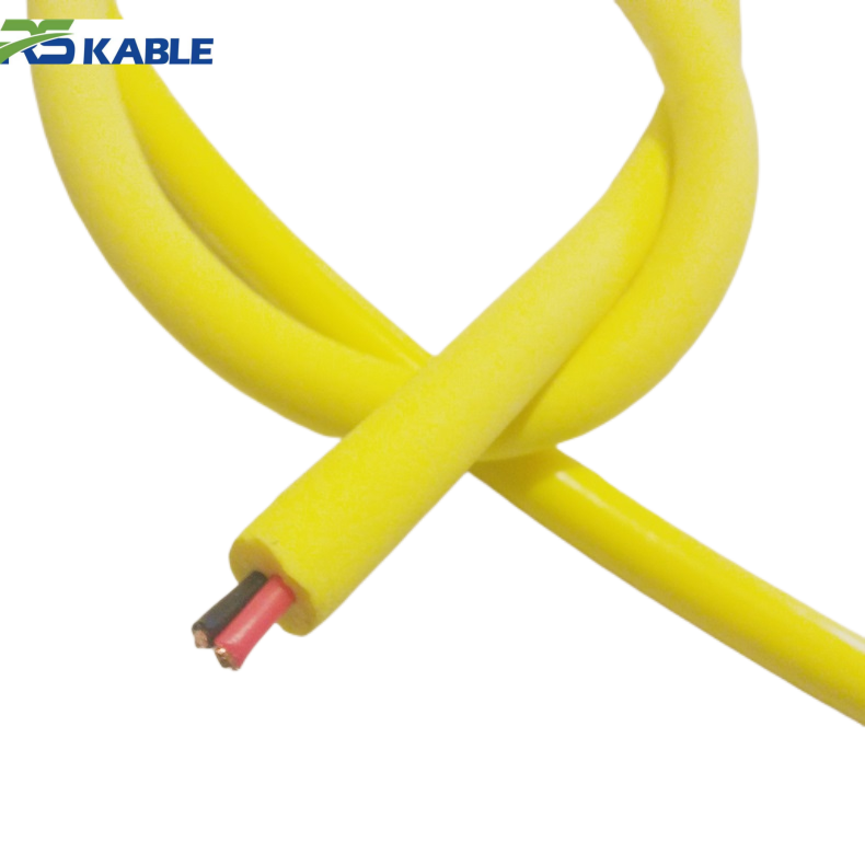



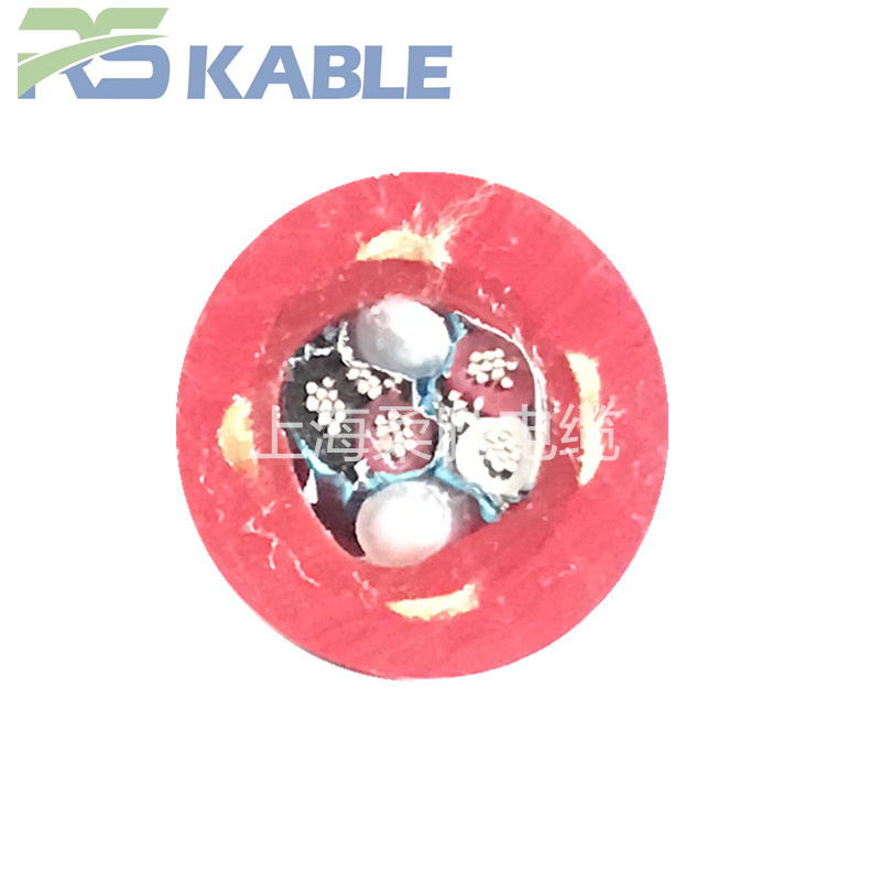
Waterproof 4-Core Twisted Pair Shielded Signal Cable | Flexible Cable for Underwater Equipment and ROV Systems
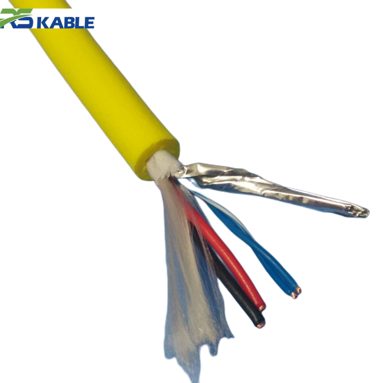
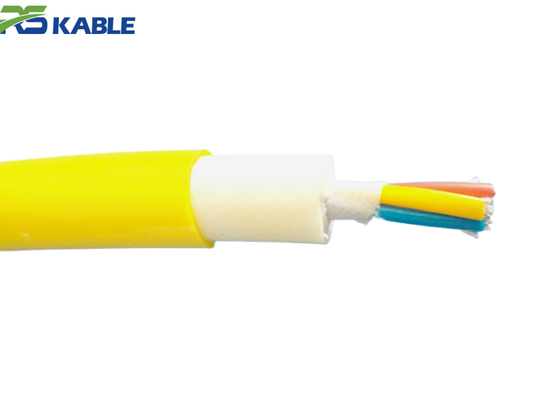
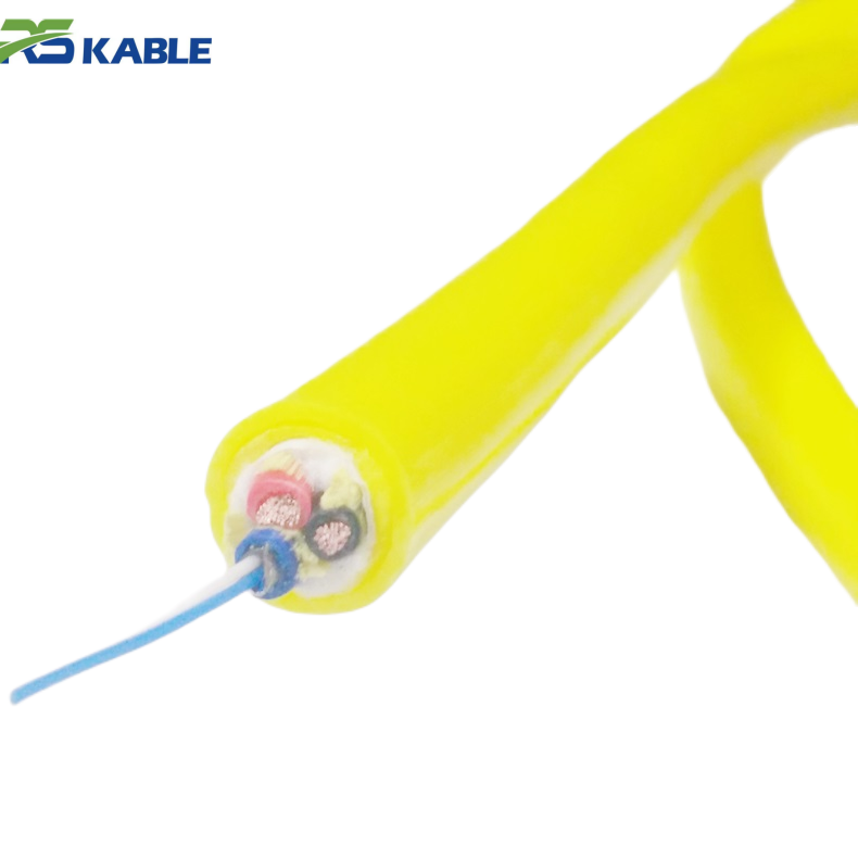
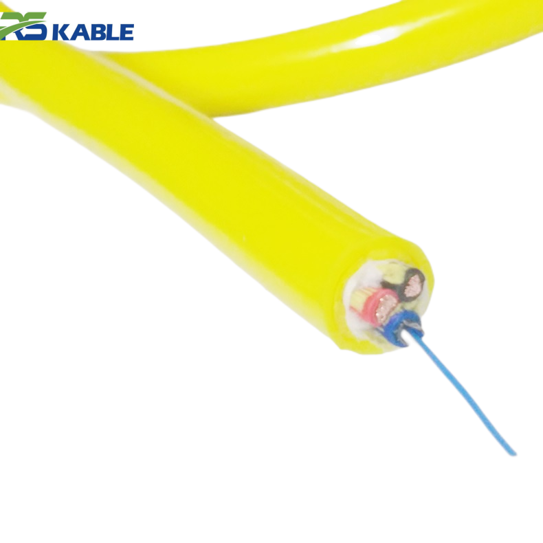
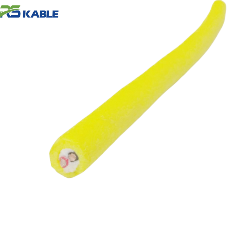
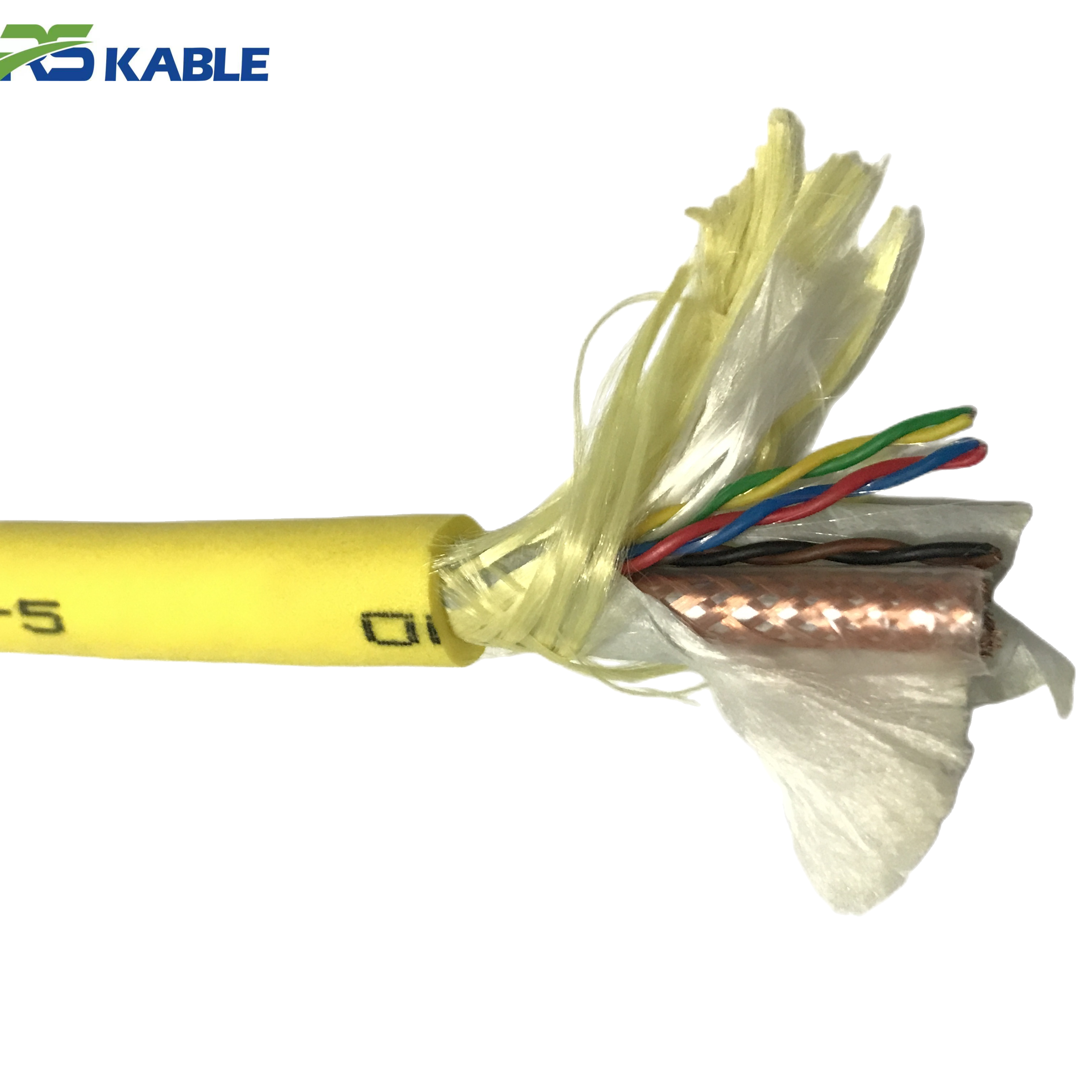
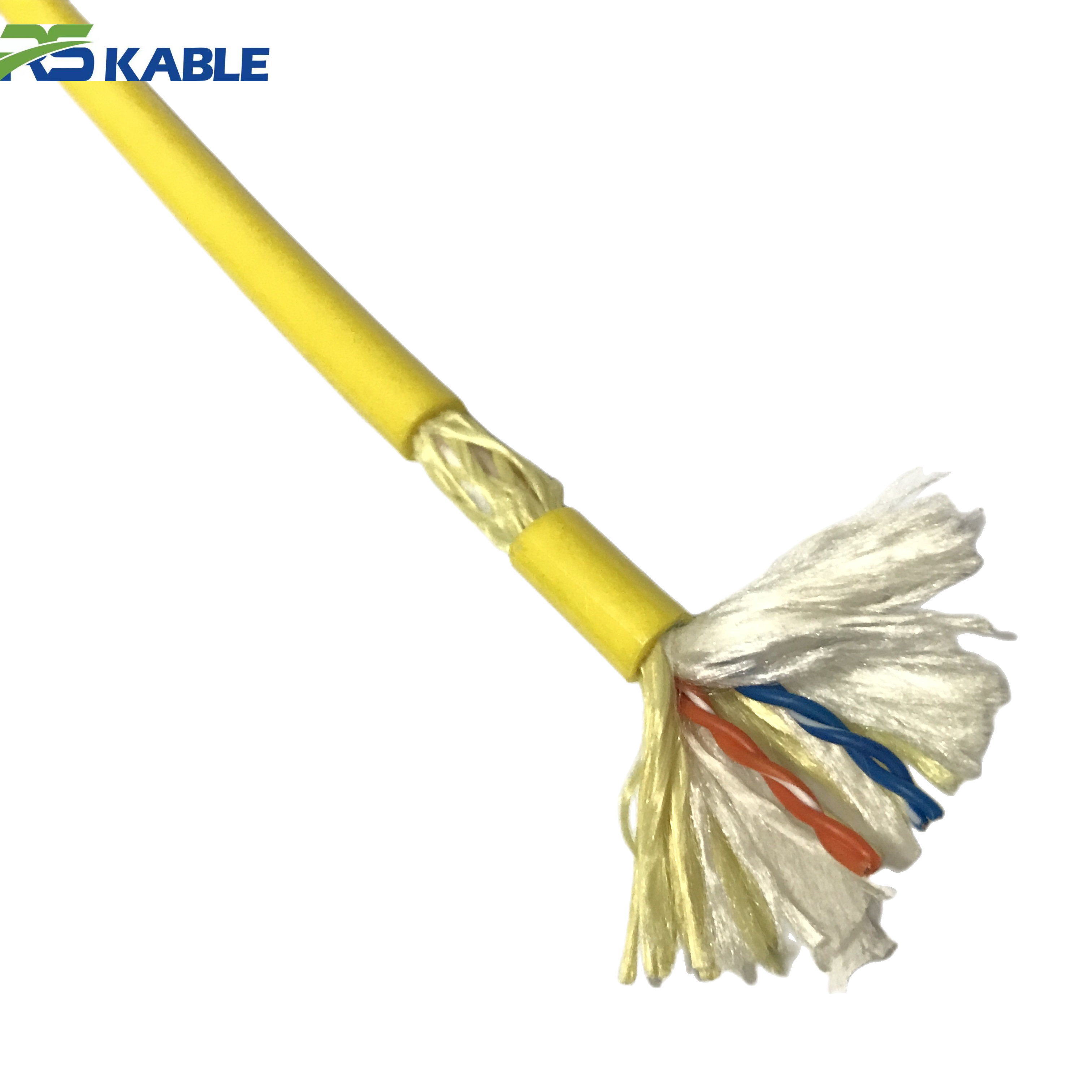
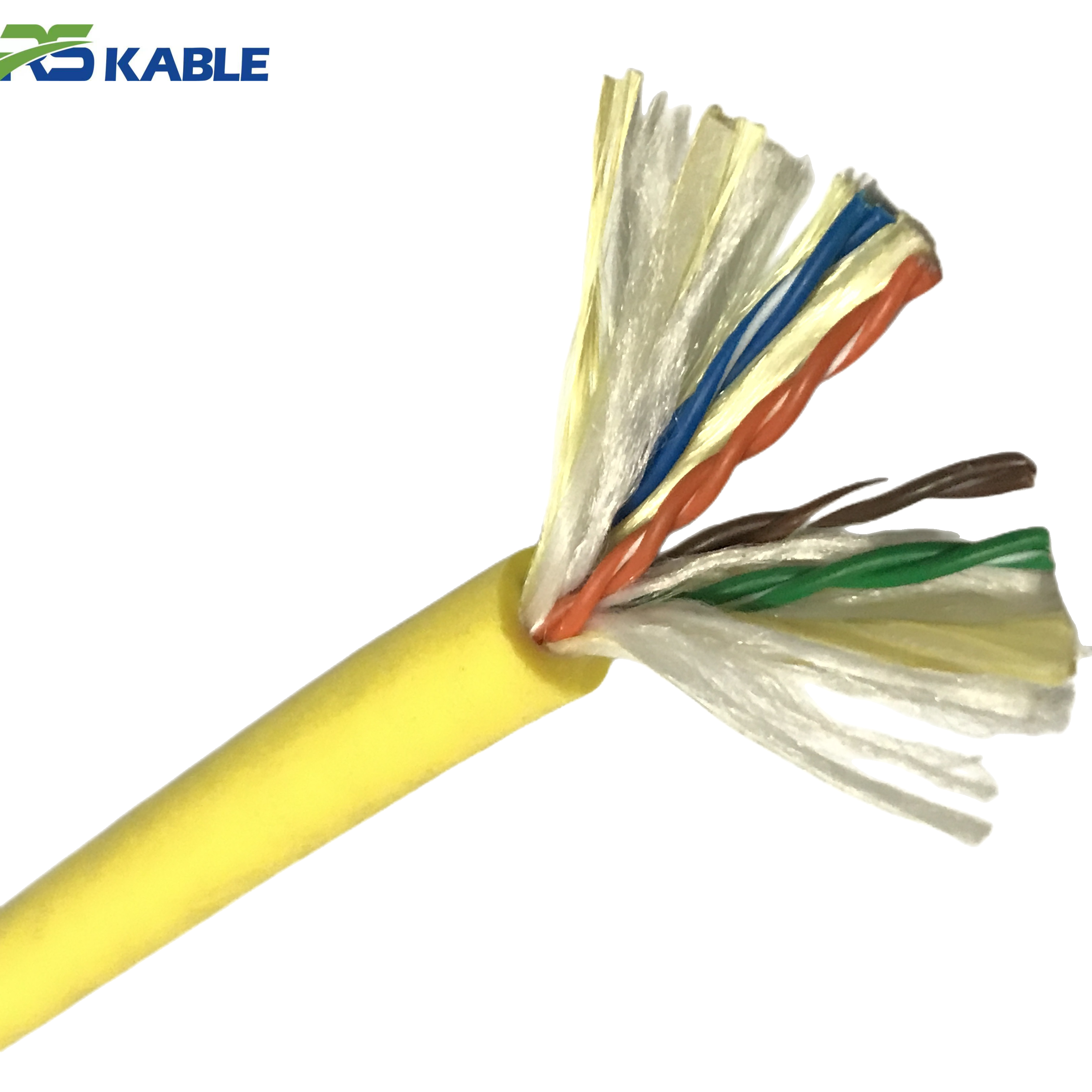
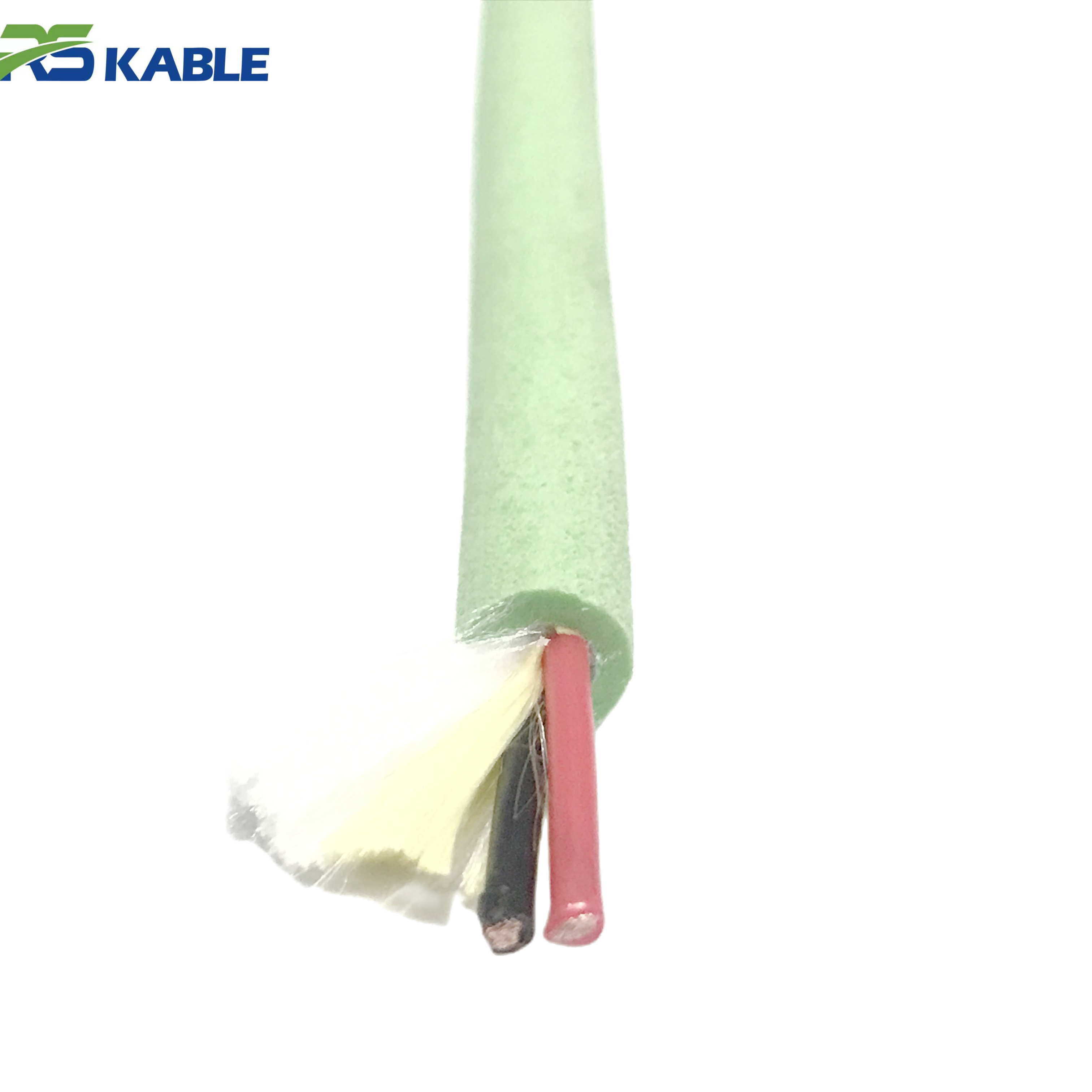
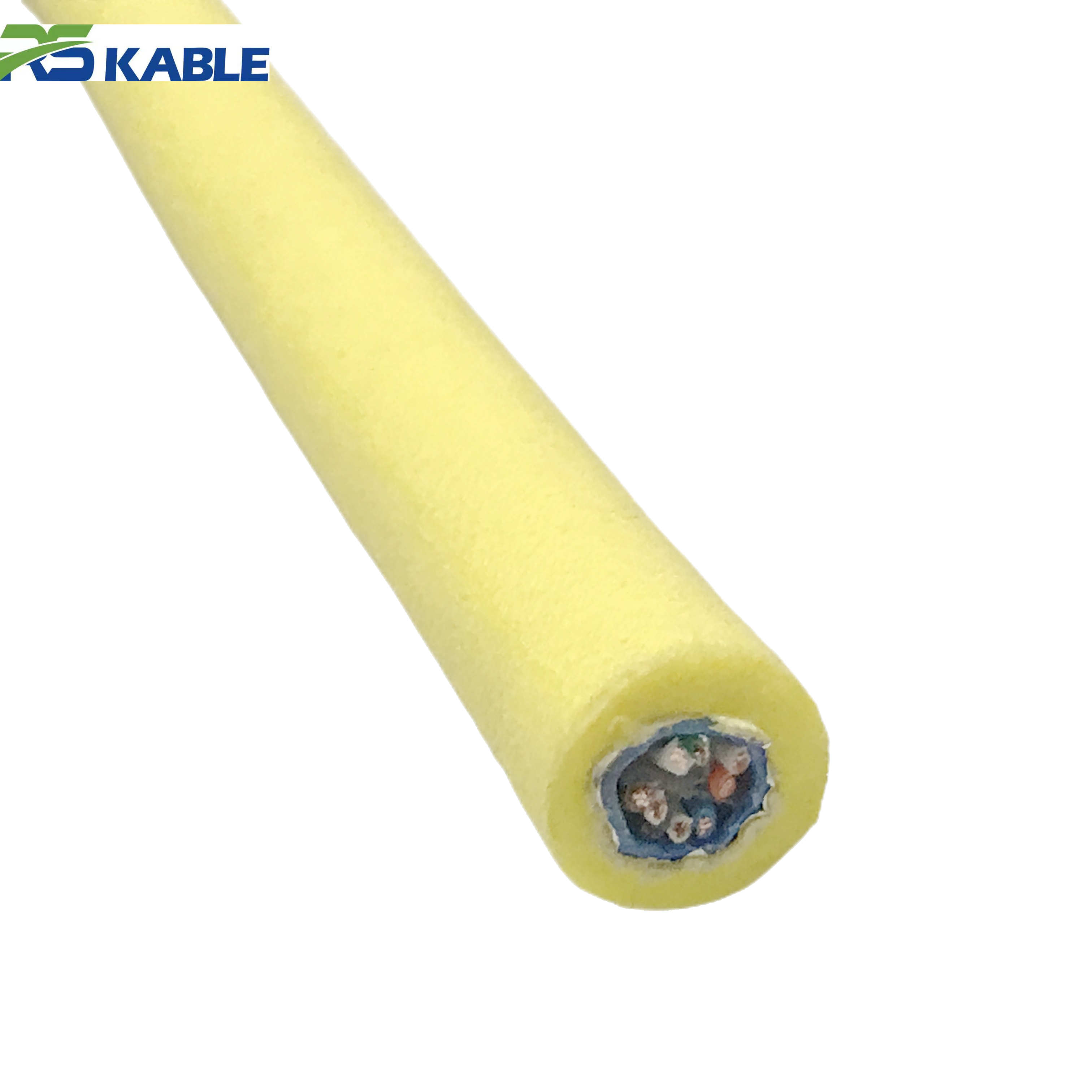
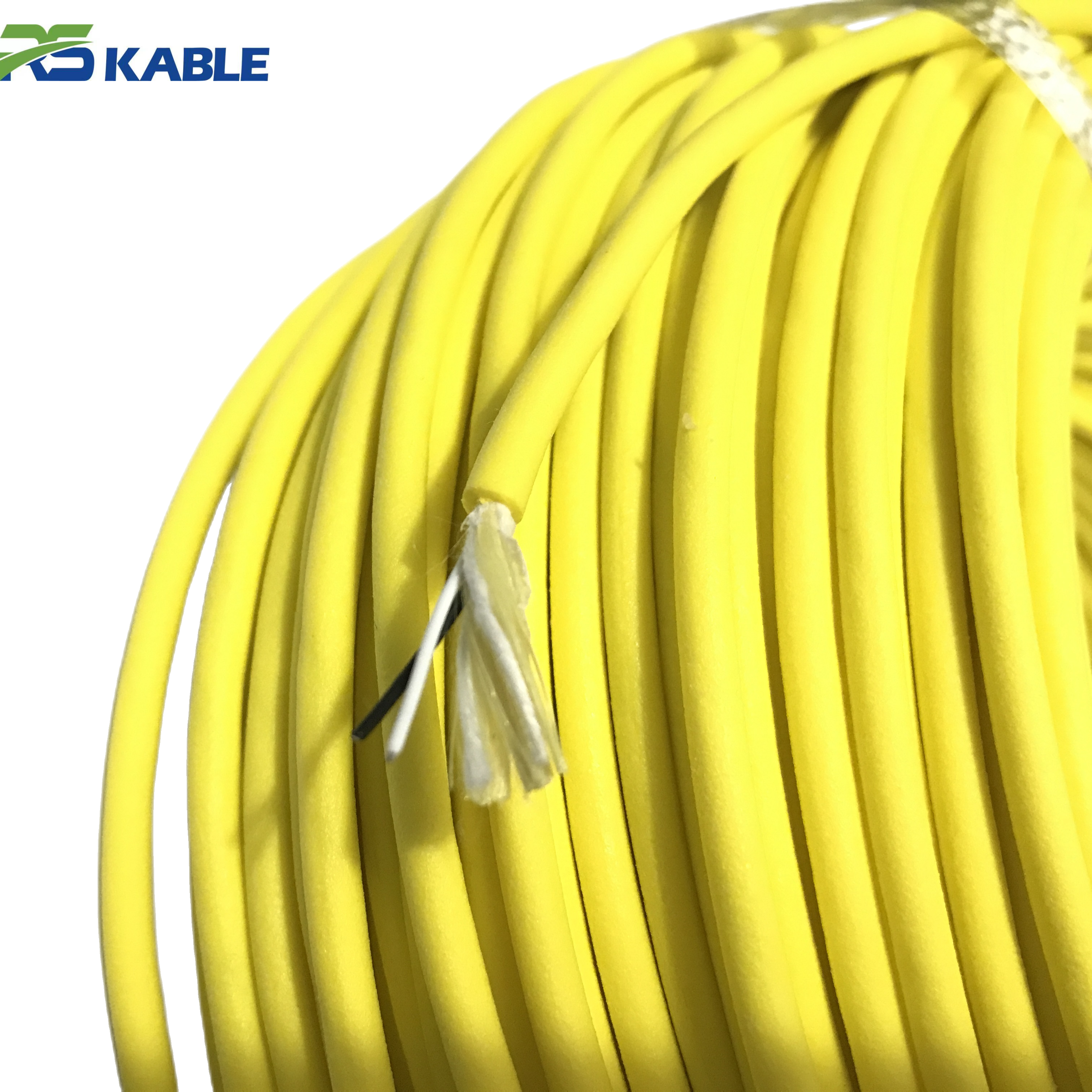
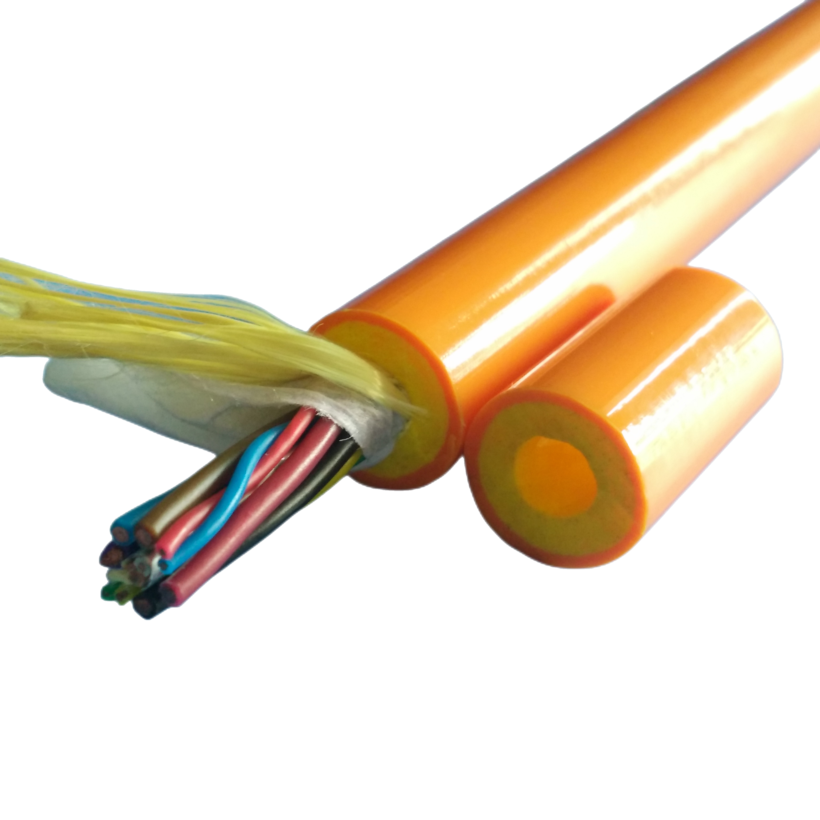
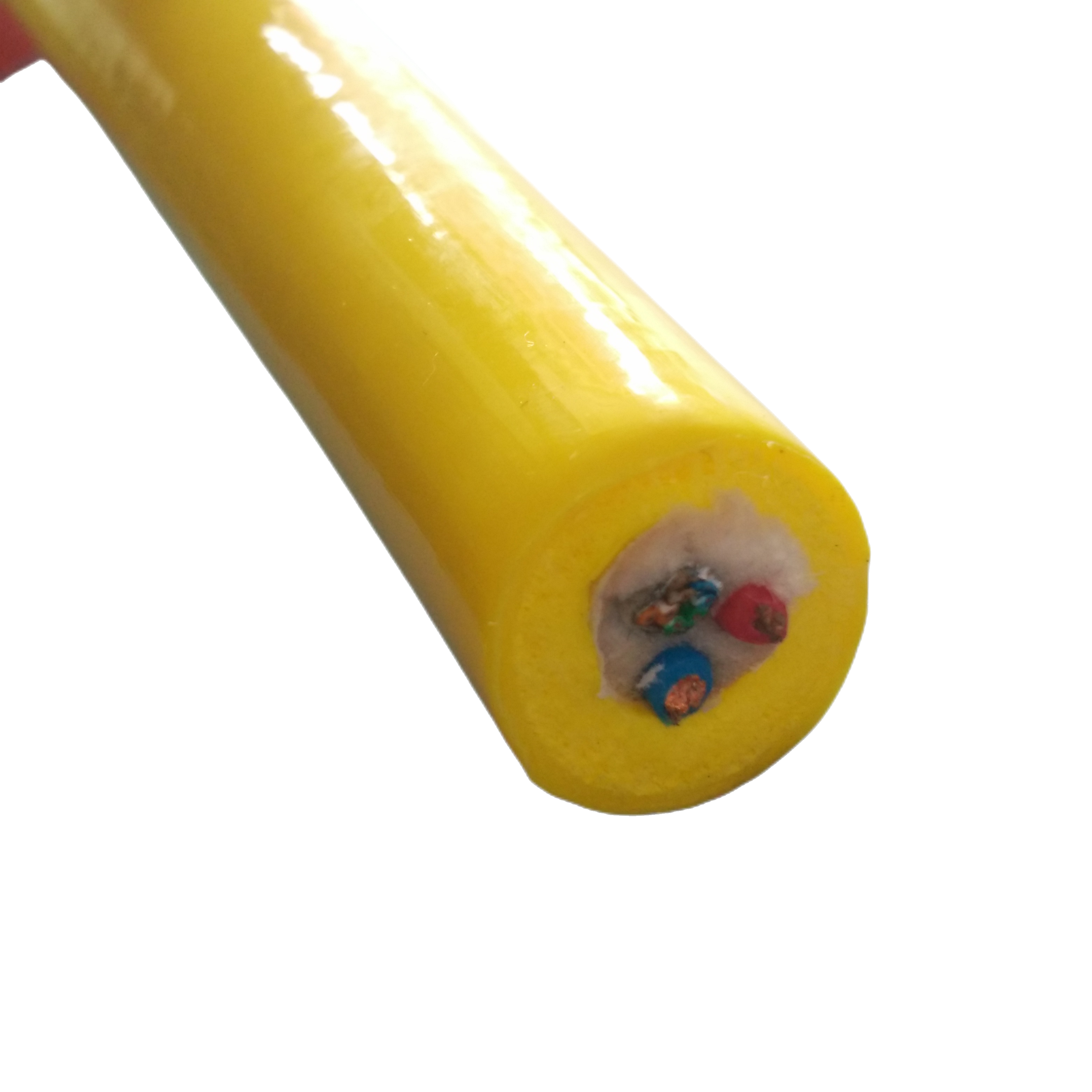
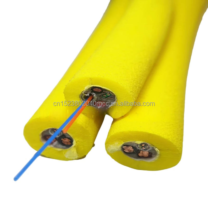
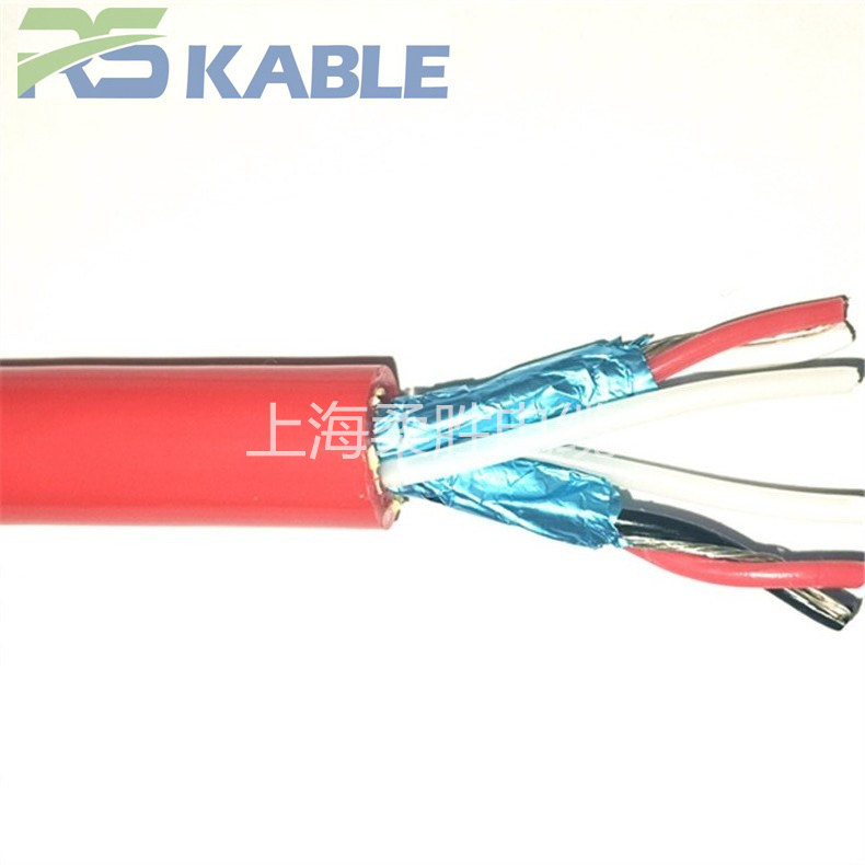
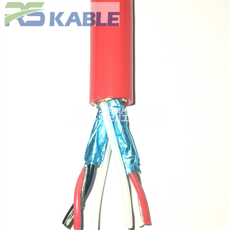
The RST-SIG-424 series is a waterproof 4-core twisted pair shielded signal cable built for differential and low-level signal links in ROV and underwater equipment. Its 120Ω twisted-pair core supports RS-485, RS-232, and 4-20mA circuits, while the shielded, flexible construction resists noise from nearby thruster and motor drives through continuous flexing.
Key benefits:
Waterproof 4-Core Twisted Pair Shielded Signal Cable for Underwater Equipment and ROV Systems
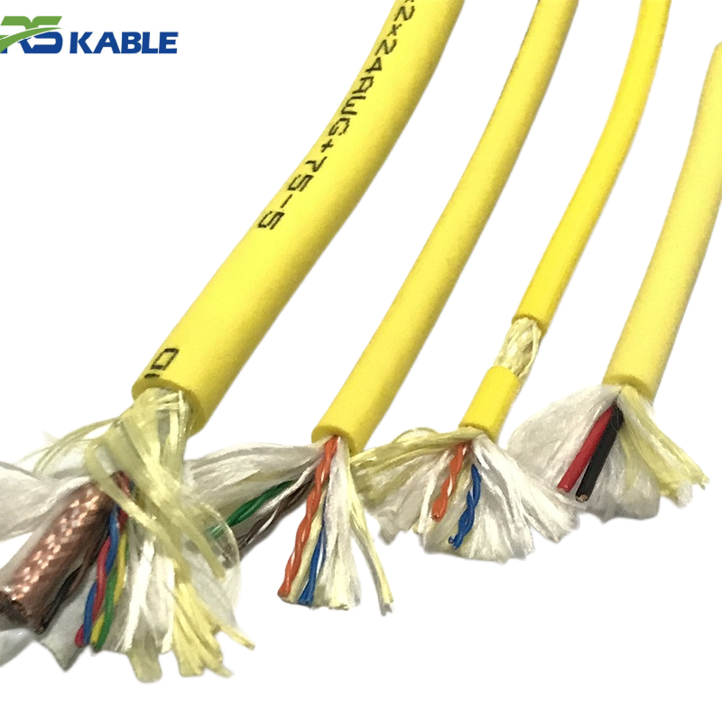
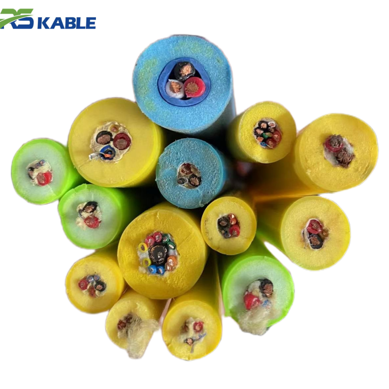
Three physical variants of this 4-core (2 twisted pair) signal cable cover most ROV and underwater equipment signal links, differing in shielding structure and jacket depth rating rather than in the underlying 24AWG twisted-pair core. The right variant depends on two questions answered below: what signal protocol and distance the link needs to support, and what physical depth and noise environment it will be routed through.
Model Line and Physical Specifications
| Model | Shielding | Outer Diameter | Depth Rating | Best Fit |
|---|---|---|---|---|
| RST-SIG-424-STD | Overall foil shield + drain wire | ≈ 5.2 mm | To 300 m | General ROV signal wiring, single circuit |
| RST-SIG-424-ISP | Individually shielded pairs | ≈ 5.8 mm | To 300 m | Two independent signal circuits in one cable |
| RST-SIG-424-DW | Overall foil shield, reinforced jacket | ≈ 6.4 mm | To 1,000 m | Deeper-water ROV and subsea equipment signal links |
| RST-SIG-424-C | Project-specified | Custom | Custom | Non-standard integration |
Signal Compatibility and Distance
| Signal Type | Typical Maximum Distance | Notes |
|---|---|---|
| RS-485 differential, up to 100 kbps | ≈ 1,200 m | Follows the standard EIA-485 distance-vs-speed relationship |
| RS-485 differential, up to 1 Mbps | ≈ 120 m | Distance drops sharply as baud rate rises |
| RS-232 single-ended | ≈ 15 m | Limited by single-ended signaling itself, not the cable |
| 4–20 mA analog current loop | Several km, power-budget dependent | Current-loop signaling tolerates cable resistance within the loop’s power supply headroom |
| Quadrature encoder feedback (differential) | Dependent on the encoder’s own output driver strength | Cable is not typically the limiting factor at standard ROV harness lengths |
Electrical Specification
| Parameter | Typical Value |
|---|---|
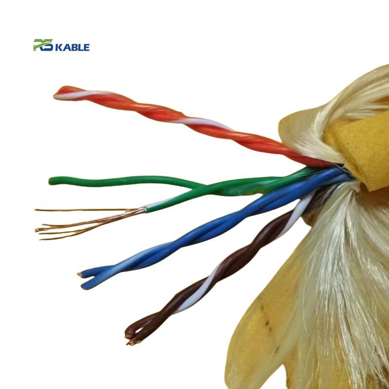
| Core configuration | 4 cores, 2 twisted pairs, 24AWG tinned copper (7×32 stranding) |
| Characteristic impedance (differential pair) | ≈ 120 Ω, consistent with standard RS-485 line termination |
| Mutual capacitance | ≈ 50 pF/m |
| Insulation resistance | ≥ 100 MΩ·km at 500 V DC |
| Flex fatigue rating | 300,000 bend cycles at rated minimum bend radius |
| Minimum bend radius | 8× overall diameter, dynamic |
| Operating temperature | -20°C to 60°C |
Construction
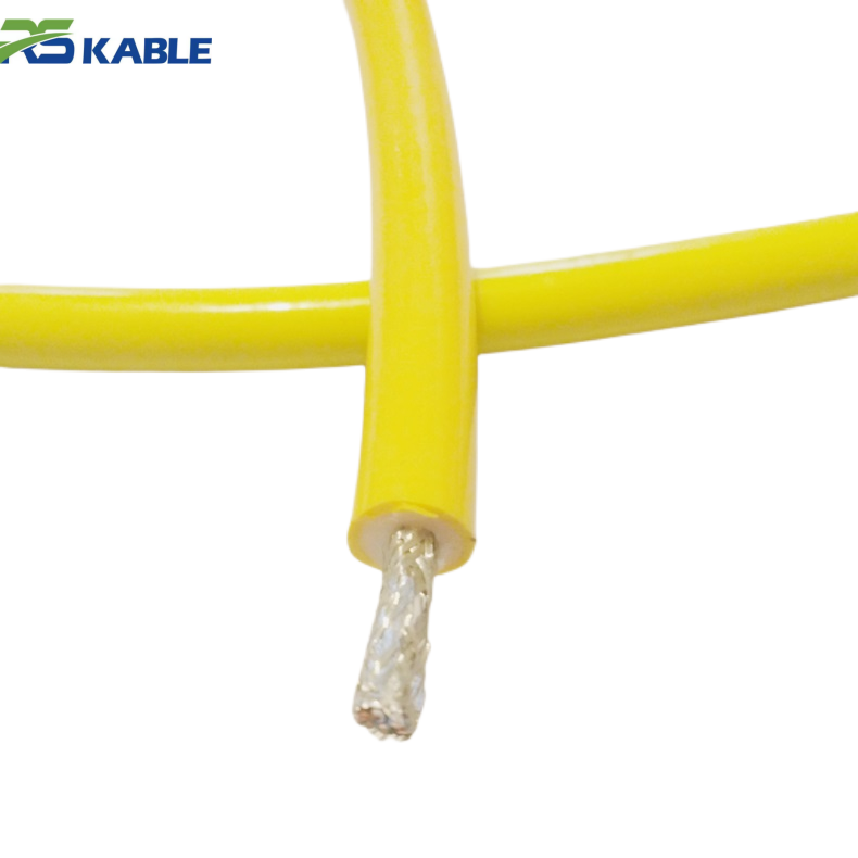
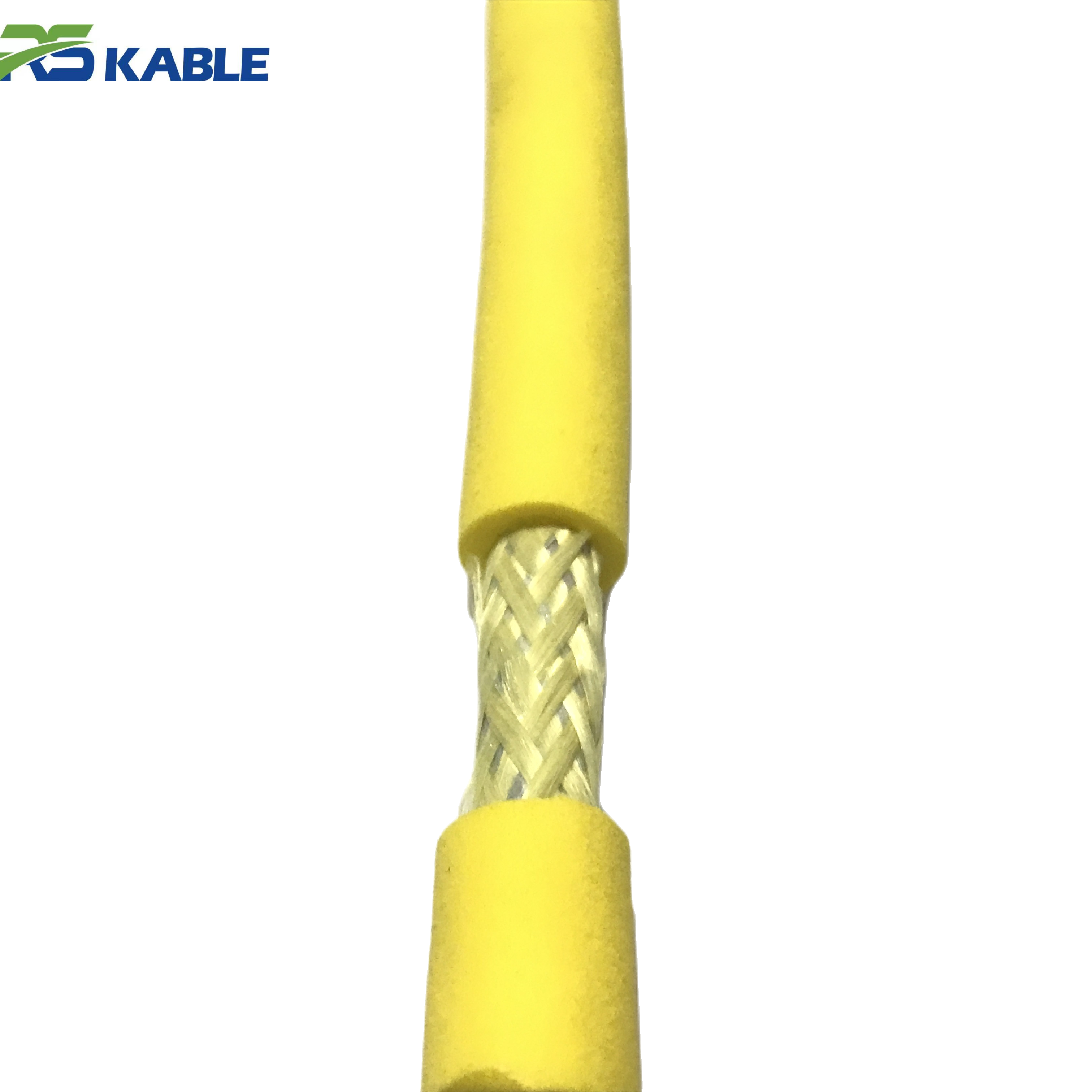
The two twisted pairs are laid at a controlled twist rate to hold the 120Ω differential impedance RS-485 and similar standards depend on, then cabled together with a torque-neutral lay to reduce twisting during flexing. The STD variant’s overall foil shield with drain wire covers both pairs as a group; the ISP variant instead shields each pair individually, isolating the two circuits from each other as well as from external noise — the distinction matters specifically when two independent signals share one cable rather than when only external noise rejection is needed. The DW variant uses the same electrical core with a thicker, reinforced jacket to extend the depth rating to 1,000 m, trading a larger outer diameter for pressure handling rather than changing the signal-carrying core itself.
Standards Framework
Electrical characteristics are designed around the differential signaling requirements described in TIA/EIA-485 (RS-485) and, for single-ended links, the general practice associated with EIA/TIA-232 (RS-232). Jacket and insulation material qualification follows the general testing philosophy of IEC 60092-350 for offshore and shipboard cable materials. These references describe the engineering framework the cable is built against rather than a claim of formal type approval for a specific installation.
Case Note: Manipulator Arm Encoder Feedback
An ROV operator retrofitting an underwater manipulator arm with encoder position feedback logged roughly 3–5 erroneous position readings per hour of continuous arm operation when using a generic unshielded twisted-pair cable routed alongside the arm’s own drive motors. After switching the same harness routing to the ISP variant of this cable, logged erroneous readings dropped to effectively zero over the operator’s subsequent recorded operating hours, with no change made to the encoder or drive electronics. This reflects one operator’s logged field experience rather than a controlled laboratory test, and results depend on the specific motor drive noise characteristics and harness routing in any given installation.
Quantified Benchmark Near Motor Drive Circuits
| Metric | Unshielded 4-Core Cable | STD (Overall Shield) | ISP (Individually Shielded Pairs) |
|---|---|---|---|
| Reported RS-485 packet loss near thruster/motor drive wiring* | ≈ 2–5% | Typically < 0.5% | Typically < 0.1% |
| Suitable for two independent signal circuits in one cable | Not recommended | Partial isolation only | Designed for this case |
| Relative cost | Lowest | Moderate | Highest |
*Figures reflect typical reported ranges for this class of installation rather than a guaranteed result for every motor drive and routing configuration; actual noise levels depend on motor type, switching frequency, and physical separation from the signal cable.
Ordering Matrix
| If your application involves… | Then specify… |
|---|---|
| RS-485 communication at a specific baud rate | Confirm required distance against the protocol table above |
| Routing near thruster or manipulator drive motors, one signal circuit | RST-SIG-424-STD |
| Two independent signal circuits sharing one cable | RST-SIG-424-ISP |
| Depth beyond 300 m | RST-SIG-424-DW |
| Continuous flexing through a moving joint or manipulator arm | Confirm the 300,000-cycle flex rating fits your duty cycle |
FAQ
Which model should I choose if I only have one signal circuit but it’s near a thruster?
RST-SIG-424-STD is the standard choice — overall shielding is sufficient for a single circuit’s external noise rejection. RST-SIG-424-ISP is intended for the specific case of two independent circuits sharing one cable, not simply for extra noise margin on one circuit.
Does the DW variant change the electrical performance of the cable?
No. The DW variant uses the same 24AWG twisted-pair core and electrical specification; only the jacket thickness changes to extend the depth rating to 1,000 m, which is why its outer diameter is larger than the STD and ISP variants.
Can this cable run true RS-485 at long distances underwater?
Yes, within the standard RS-485 distance-versus-baud-rate relationship — roughly 1,200 m at 100 kbps, dropping as baud rate increases. This is a property of the RS-485 signaling standard itself, not something the cable can exceed.
How much does shielding actually help near motor drive circuits?
Based on the reported ranges above, unshielded cable in this kind of installation has shown packet loss in the low single-digit percent range, while the shielded variants have shown substantially lower reported loss. Actual results depend on the specific motor and routing, so this is a general expectation rather than a guarantee for any one installation.
Is custom depth rating or shielding configuration available beyond these three models?
Yes. RST-SIG-424-C covers non-standard depth, shielding, or conductor requirements outside the three standard models.
Technical content reviewed by the cable engineering team prior to publication. Figures represent typical performance for this construction and signaling standard; request a project-specific test certificate for long-distance or safety-relevant installations.