


ROV Underwater Thruster Cable | Flexible Power & Control Cable for Subsea ROV Systems
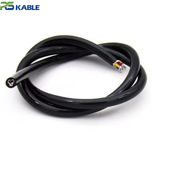
The RST-ROV-TC series is a flexible subsea power and control cable for ROV thruster wiring and internal harness routing. Its torque-balanced, water-blocked construction resists kinking and water ingress through repeated launch and recovery cycles.
Key benefits:
ROV Underwater Thruster Cable: Flexible Power and Control Cable for Subsea ROV Systems
Cable selection for ROV thruster and internal harness wiring is driven first by depth class, not by core count. A cable built for a 300 m observation-class vehicle and one built for a 1,500 m work-class vehicle are different engineering problems — different tensile requirements during launch and recovery, different insulation qualification, and in some cases a different jacket construction entirely. The tiers below outline how this cable’s specification changes across common ROV depth classes, followed by the test data, construction detail, and ordering information behind each tier.
Depth Classification and Cable Tiers
| Tier | Depth Class | Typical Vehicle Type | Conductor Size | Reinforcement | Tensile Breaking Load | Engineering Notes |
|---|---|---|---|---|---|---|
| Tier 1 | To 300 m | Observation-class ROV | 0.5–1.0 mm² | Light aramid braid | ≈ 40 kgf | Standard catalog construction, suitable for most inspection-class deployments |
| Tier 2 | 300–1,500 m | Work-class ROV | 0.75–2.5 mm² | Full aramid braid, water-blocked cores mandatory | ≈ 120 kgf | Standard catalog construction with mandatory gel-filled cores |
| Tier 3 | 1,500–6,000 m | Deep-water / full-ocean-depth ROV | Project-specified | Project-specified, may include pressure-balanced oil-filled (PBOF) design | Project-specified | Requires engineering review; not a standard catalog item |
Tier 1 and Tier 2 constructions are available as standard catalog items with the test data below. Tier 3 depth classes require a project-specific engineering review because pressure compensation, material compressibility, and connector interface all change materially beyond roughly 1,500 m.
Standards Framework
The dimensional and material approach for this cable is consistent with the general principles set out in API 17E for subsea umbilical and umbilical-branch cable design, and insulation/sheath material qualification follows the testing philosophy of IEC 60092-350 for shipboard and offshore electrical cable materials. These references describe the engineering framework the construction is built against; they are not a substitute for a project-specific type approval. Where a classification society type approval (DNV-GL, ABS, or equivalent) is required for a specific vessel or vehicle certification, that approval is arranged as a project service tied to the exact construction ordered, rather than issued generically for the catalog product.
Electrical and Mechanical Test Data (Tier 1 / Tier 2)
| Test | Typical Result |
|---|---|
| Insulation resistance | ≥ 100 MΩ·km at 500 V DC |
| Dielectric withstand | 2,000 V AC, 1 minute, core-to-core and core-to-shield |
| Bend cycle rating | 250,000 cycles at rated minimum bend radius (spooling fatigue test) |
| Water-block verification | No core-to-core water migration after 24 hours submerged at 10 bar differential pressure, following intentional local jacket breach |
| Tensile breaking load, Tier 1 | ≈ 40 kgf |
| Tensile breaking load, Tier 2 | ≈ 120 kgf |
| Abrasion resistance (jacket) | No breach after standard reciprocating abrasion test at rated cycle count for jacket class |
These figures are typical qualification results for the construction class described; a shipment-specific test certificate should be requested for classification-society submissions or safety-critical deployments.
Construction Cross-Section
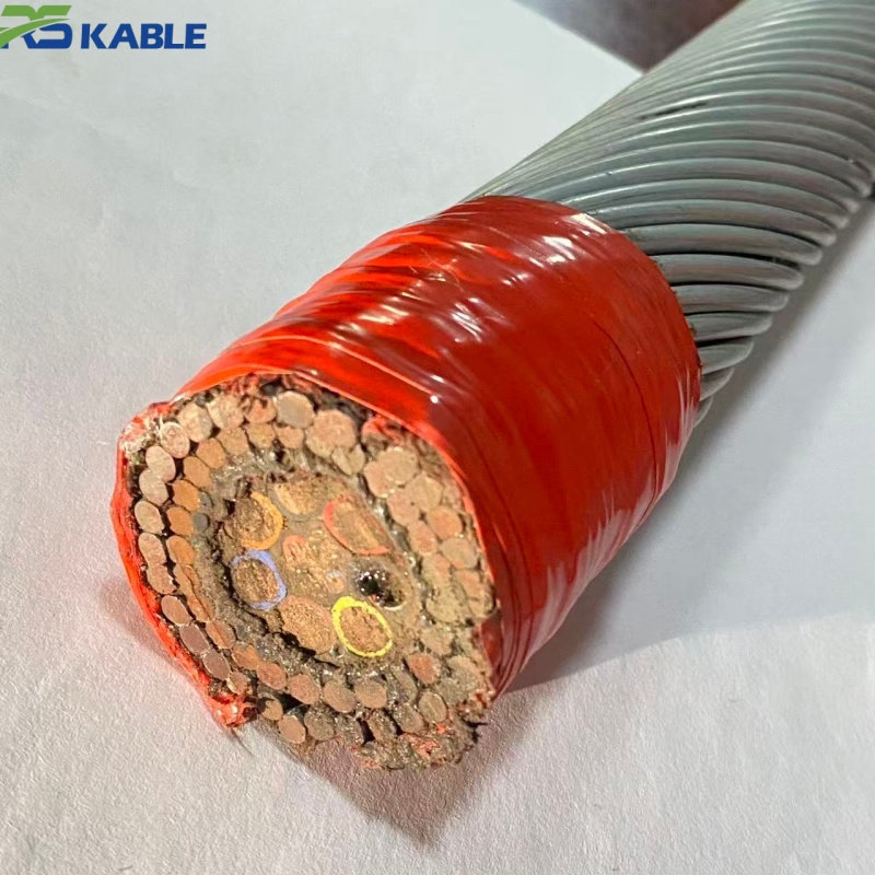
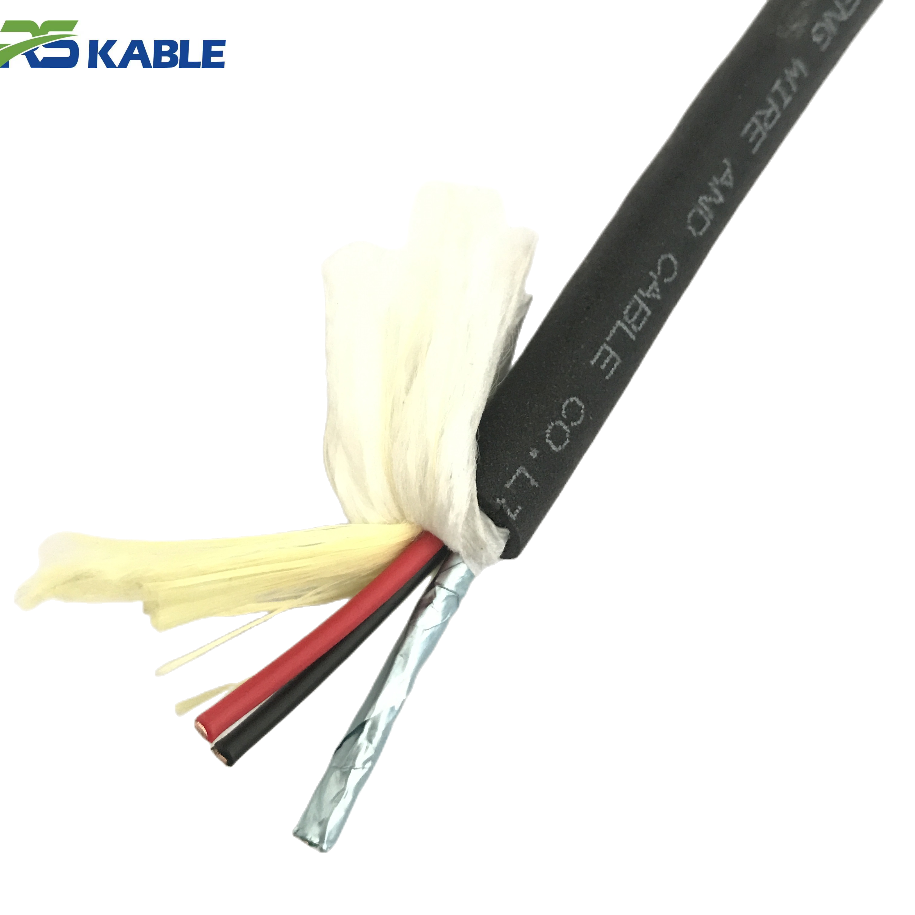
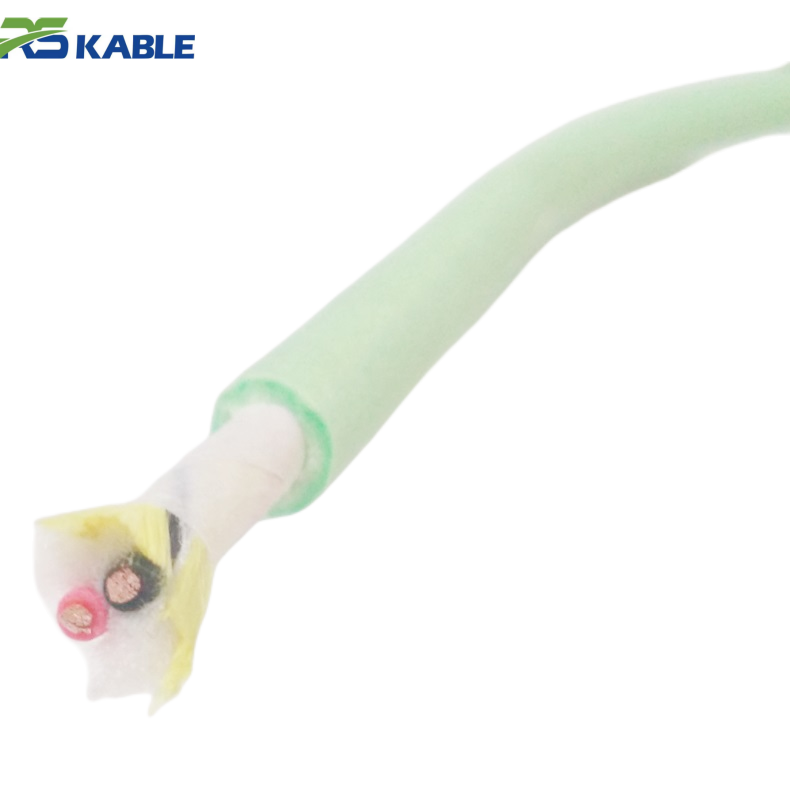
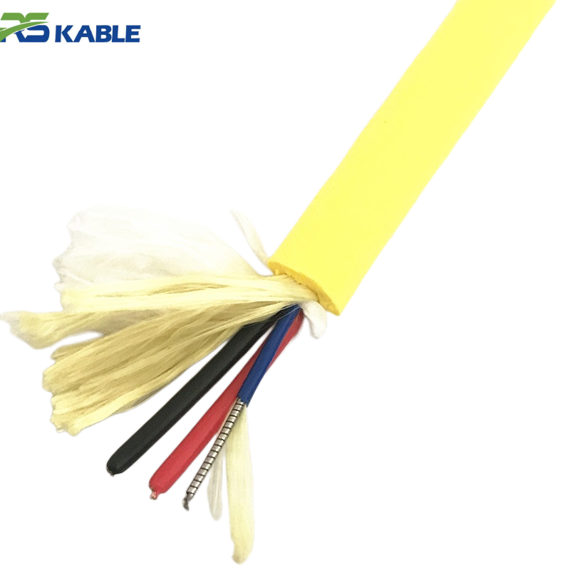
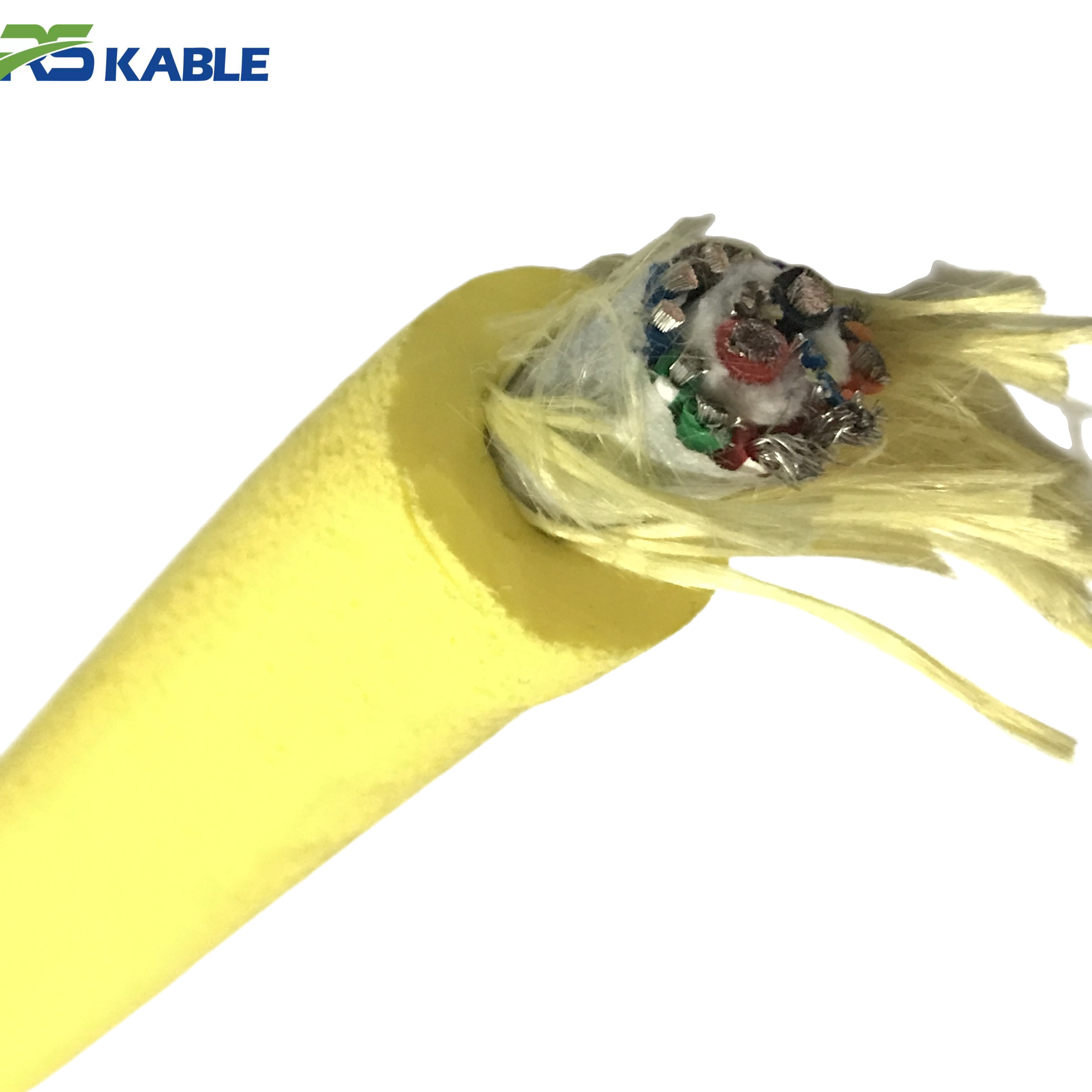
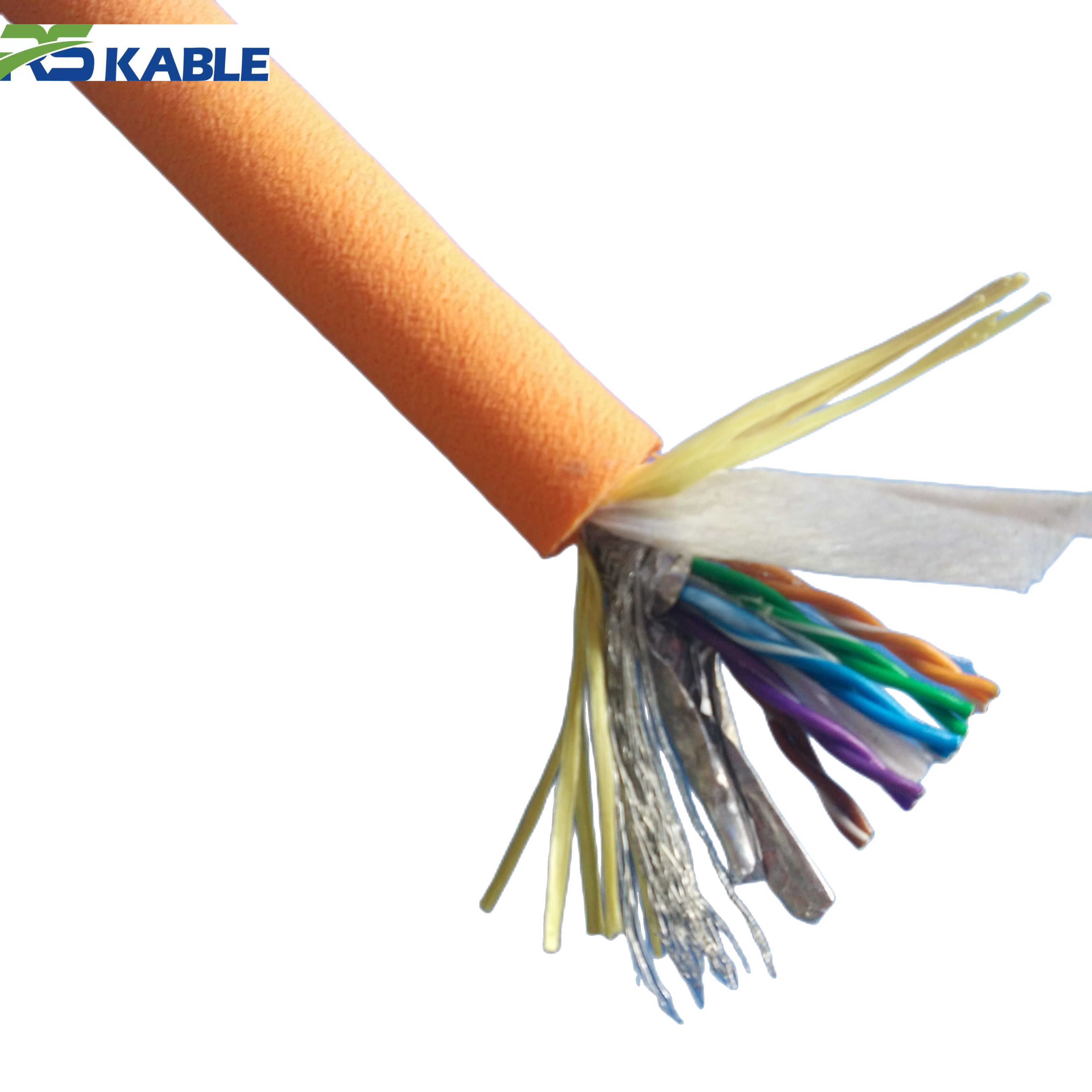
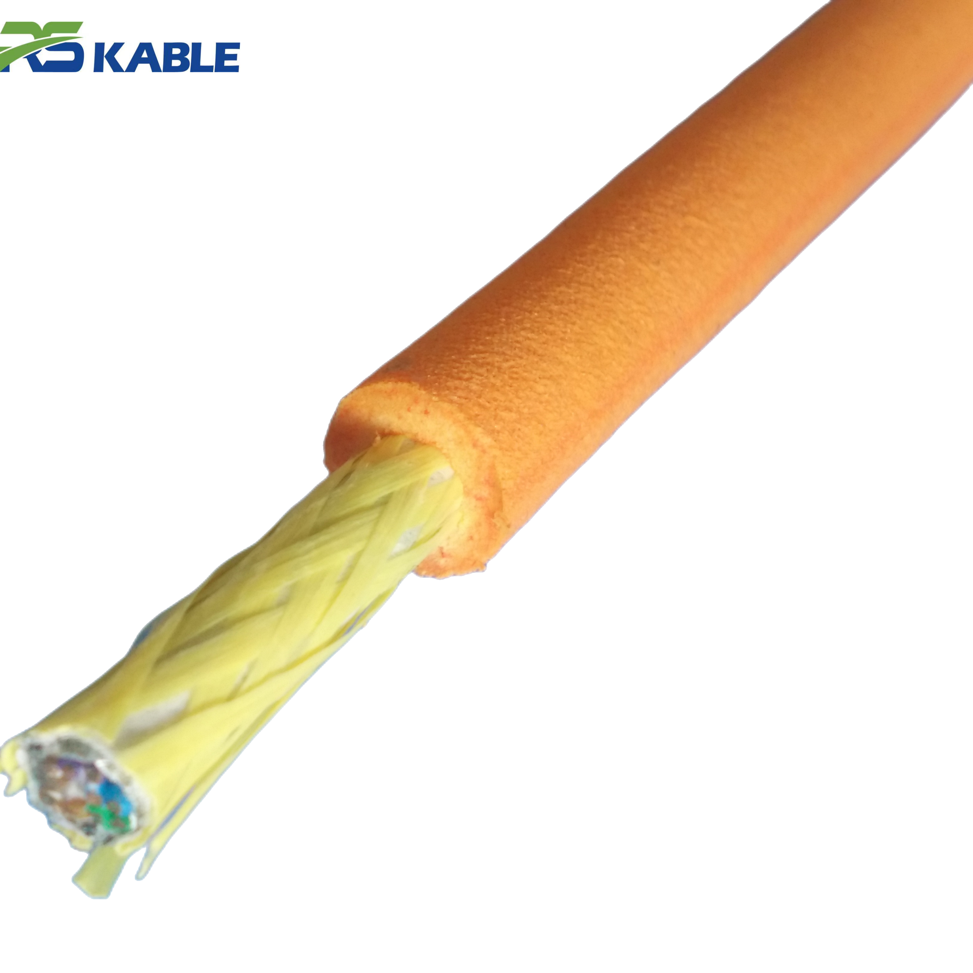
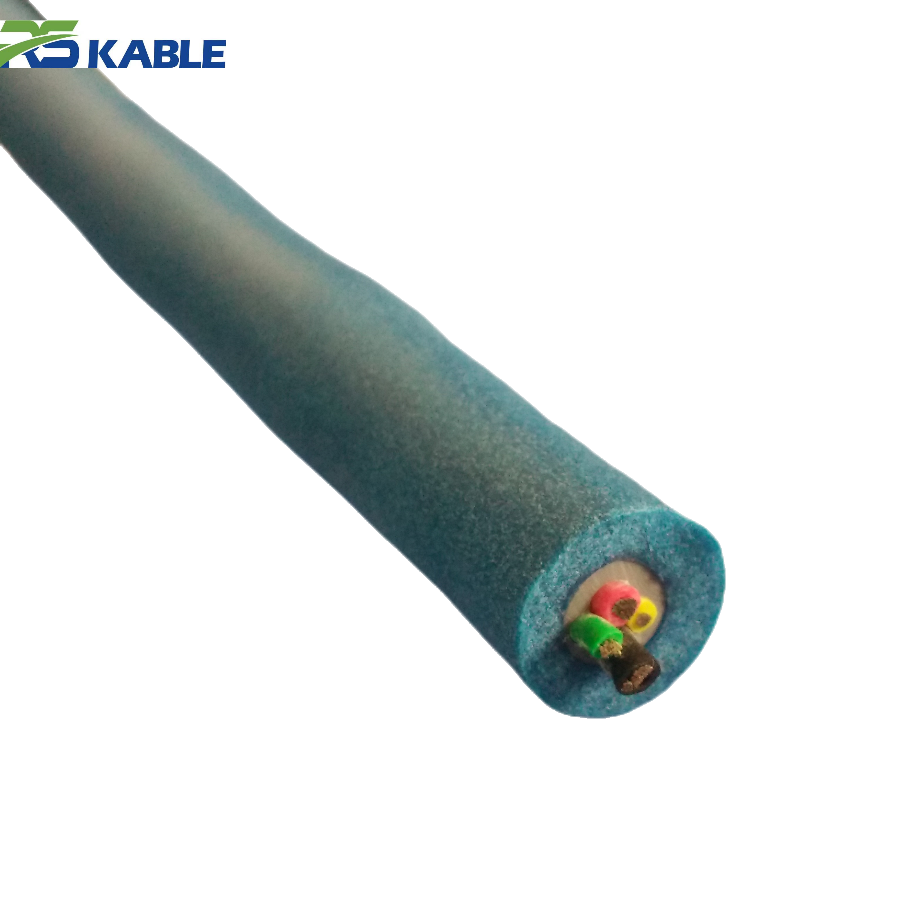
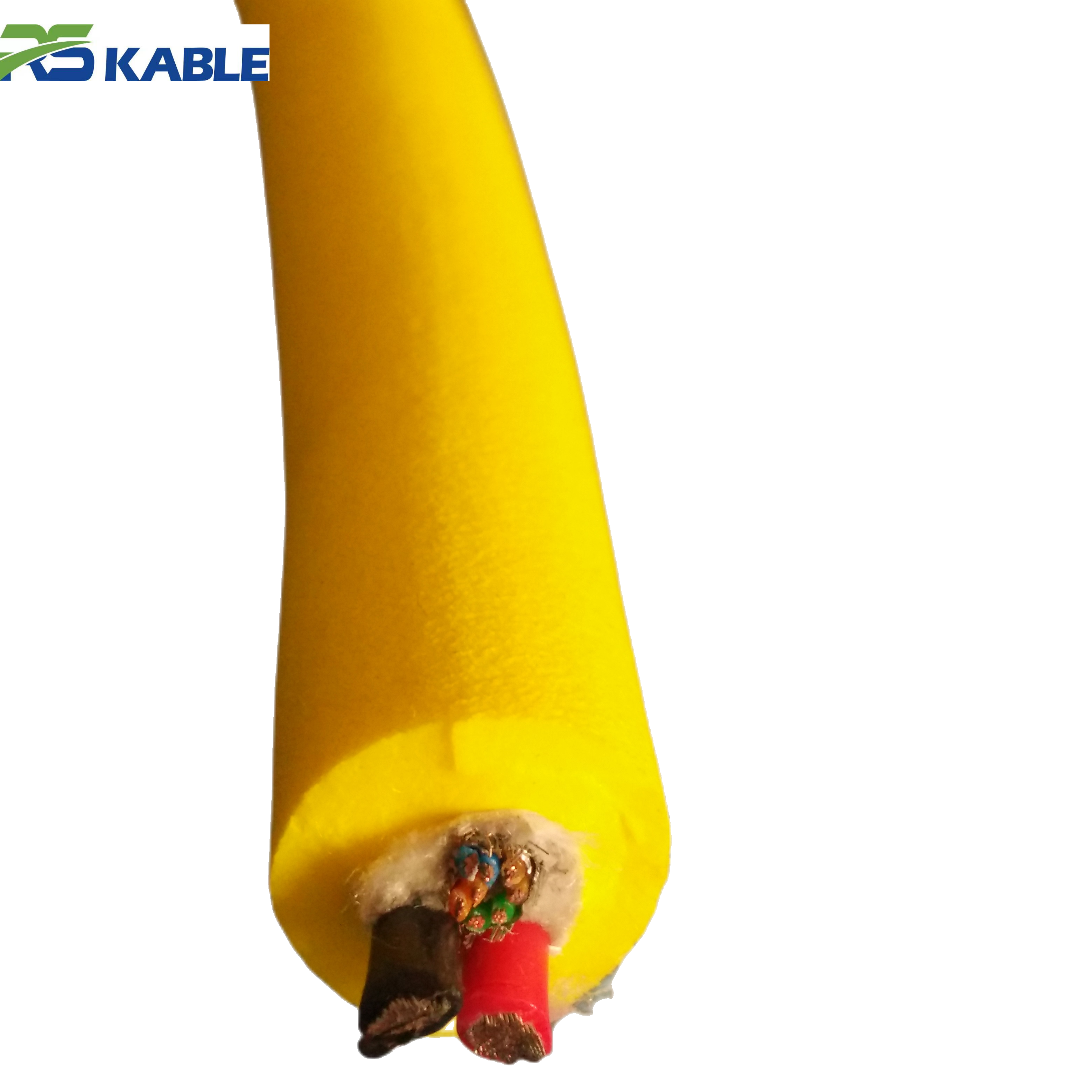
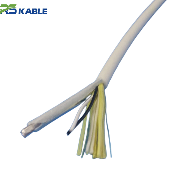
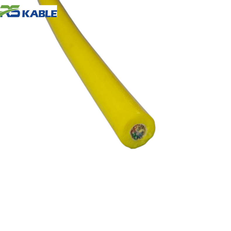
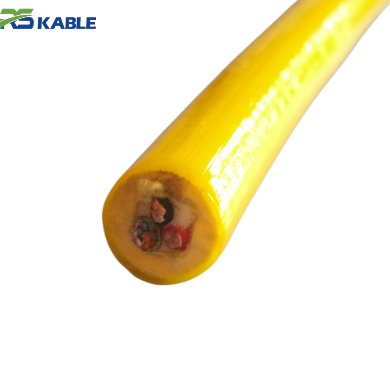
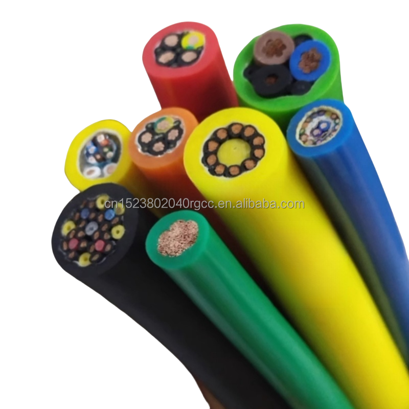
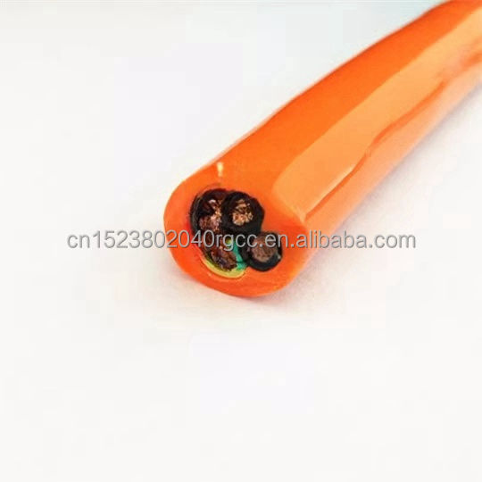
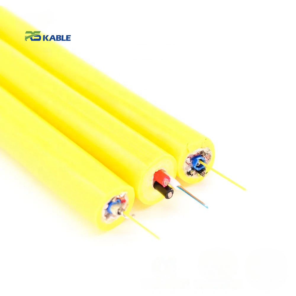
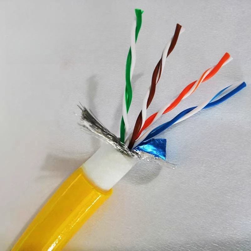
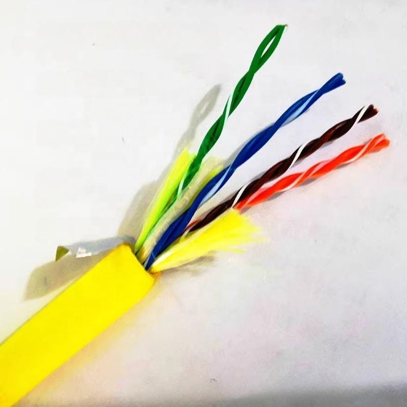
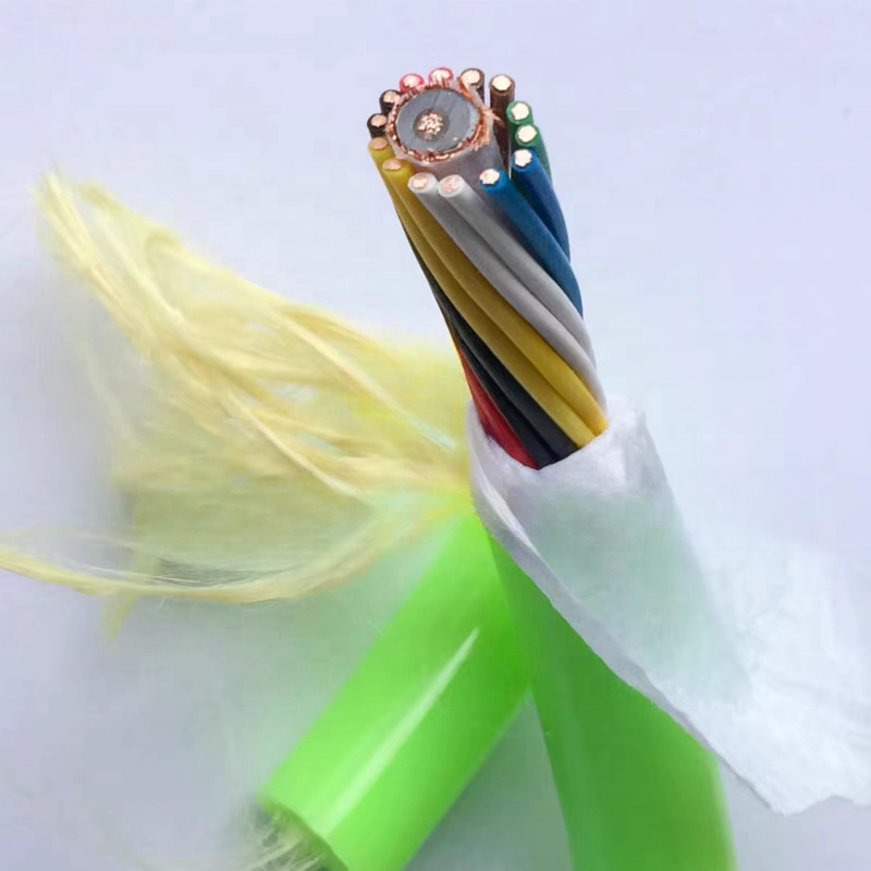
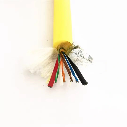
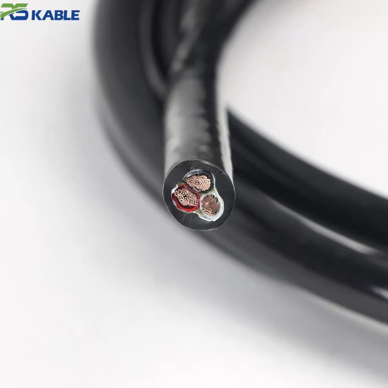
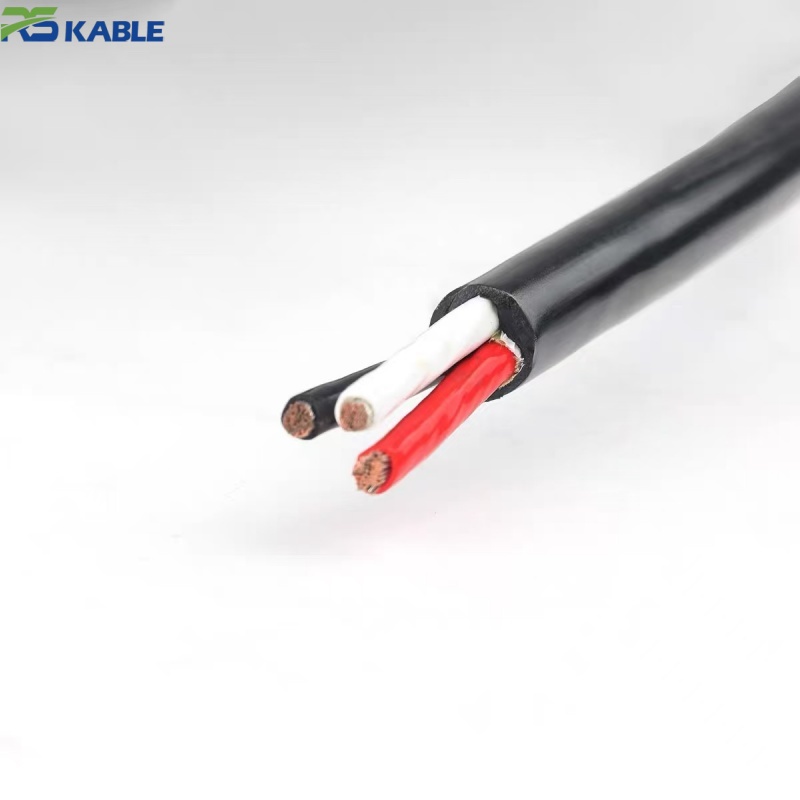
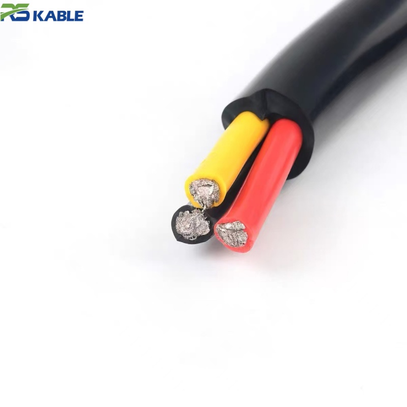
Working from the center outward, the cable is built as: tinned copper conductors (fine-stranded for flex tolerance) → water-blocking compound or gel fill directly at the conductor/insulation interface → PE or TPE insulation → a torque-balanced lay of the individual cores, arranged so opposing layers cancel twist under tension rather than adding to it → an aramid braid reinforcement layer sized to the tier’s tensile requirement → an outer polyurethane jacket selected for abrasion and hydrolysis resistance in sustained seawater contact. The torque-balancing step is the one most often skipped in generic marine cable, and it is the step most responsible for whether a cable kinks after a dozen launch-and-recovery cycles or after several hundred.
Deployment and Handling Notes
Most in-service cable damage on ROV internal harnesses traces back to handling events rather than gradual material aging — a cable pinched at a thruster pod entry point during reassembly, or tension applied at an angle across a frame edge rather than in-line during a retrieval. Two practices reduce this risk regardless of which tier is specified: routing the cable through a dedicated strain-relief boot at every pod or connector entry point rather than relying on the jacket alone, and inspecting the bend radius at the tightest point in the harness path against the tier’s rated minimum — a harness designed around the cable’s straight-line length without checking the tightest corner is a common source of premature fatigue that has nothing to do with the cable’s rated cycle life.
Field Pattern: Work-Class ROV Fleet Retrofit
An offshore inspection contractor operating a small fleet of work-class ROVs reported that thruster harness cables using a non-torque-balanced construction required unscheduled replacement due to kinking roughly every 150–200 launch/recovery cycles. After switching thruster harnesses to a torque-balanced, aramid-reinforced construction of this type, reported kink-related replacements dropped to roughly once per 800–1,000 cycles across the fleet’s logged maintenance records. This is a single operator’s reported maintenance pattern rather than a controlled comparative trial, and actual results depend on winch handling practice, harness routing, and vehicle-specific pod geometry.
Comparative Data vs Conventional Umbilical Branch Cable
| Metric | This Construction (Tier 2) | Conventional Non-Torque-Balanced Branch Cable |
|---|---|---|
| Tensile breaking load | ≈ 120 kgf | Typically 40–60 kgf, unreinforced |
| Bend cycle rating | 250,000 cycles | Not typically rated for repeated flex |
| Reported kink-related replacement interval* | ≈ 800–1,000 launch/recovery cycles | ≈ 150–200 launch/recovery cycles |
| Water-block verification | Included as standard test | Not typically included |
| Torque balance | Engineered into core lay | Not typically engineered |
*Interval figures are drawn from the fleet retrofit pattern above and general reporting for this cable class; they are not a guaranteed replacement schedule for every vehicle and deployment profile.
Ordering Specification
| Field | What to Provide |
|---|---|
| Depth tier | Tier 1 (to 300 m), Tier 2 (300–1,500 m), or Tier 3 (1,500–6,000 m, engineering review required) |
| Circuit type | Power only, control/signal only, or combined |
| Core count and conductor size | Based on thruster power draw and control circuit design |
| Tensile requirement | Expected load during launch and recovery, including any angled-pull scenarios |
| Connector interface | Underwater-mateable, dry-mate, or project-specific pod connector |
| Certification requirement | Classification society type approval needed, and which society |
Technical Notes
Why does depth tier change the cable more than the phrase “rated to X meters” suggests? Past roughly 1,500 m, material compressibility under hydrostatic pressure starts to matter as much as insulation and jacket chemistry — a construction that performs well at 500 m is not automatically safe to specify at 3,000 m without re-evaluating compressible air gaps and connector interfaces. That is why Tier 3 is treated as an engineering review rather than a simple depth-rating extension of Tier 2.
Is torque balancing something that can be added to any existing cable design, or does it require a different build from the start? It has to be engineered into the core lay from the start — it is a function of how the individual cores are twisted together, not a coating or added layer that can be retrofitted onto a completed cable.
Does the 250,000-cycle bend rating mean the cable is guaranteed to last that many launch and recovery events? No — the bend cycle rating is a laboratory fatigue test at the rated minimum bend radius under controlled conditions. Field life depends heavily on whether the actual harness routing respects that same minimum radius at its tightest point, which the deployment notes above address directly.
What is actually required to get classification society type approval, and is it included by default? Type approval is tied to the exact construction, connector, and installation drawing submitted to the society, so it is arranged per project rather than issued as a blanket certificate for the catalog item. If a specific vessel or vehicle certification requires it, this should be flagged at the ordering stage so the correct documentation package is prepared alongside production.
How does a Tier 2 cable behave if it is occasionally deployed slightly beyond its rated depth during an unplanned dive? Occasional excursions modestly beyond a Tier 2 rating are a different question from routine Tier 3 operation, but neither is covered by the standard Tier 2 test data above. Any planned or expected depth beyond the stated tier should be specified up front rather than treated as an occasional exception, since the insulation and connector interface — not just the jacket — are what actually change at greater depth.
Technical content reviewed by the cable engineering team prior to publication. Figures represent typical performance for the construction and test methodology described; request a shipment-specific certificate for classification-society submissions or safety-critical deployments.