


Flexible Pneumatic Tube Composite Cable | Combined Electrical and Air Line Cable for Automation
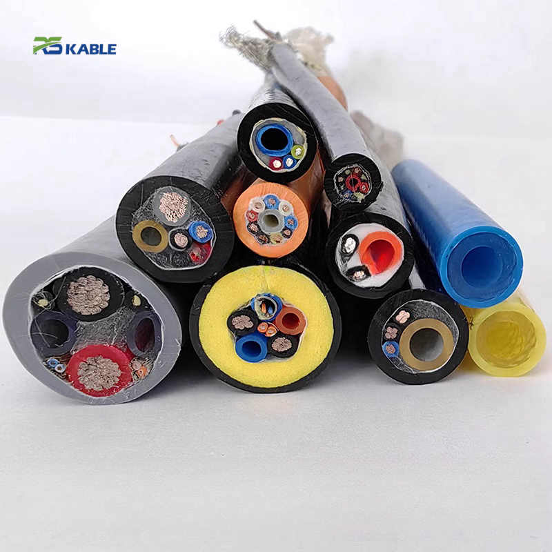
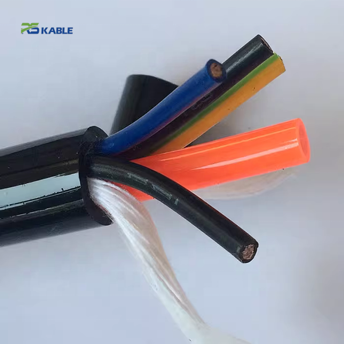
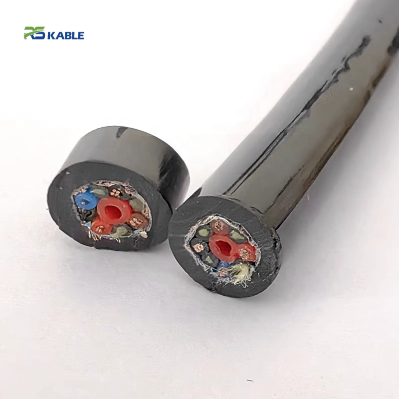
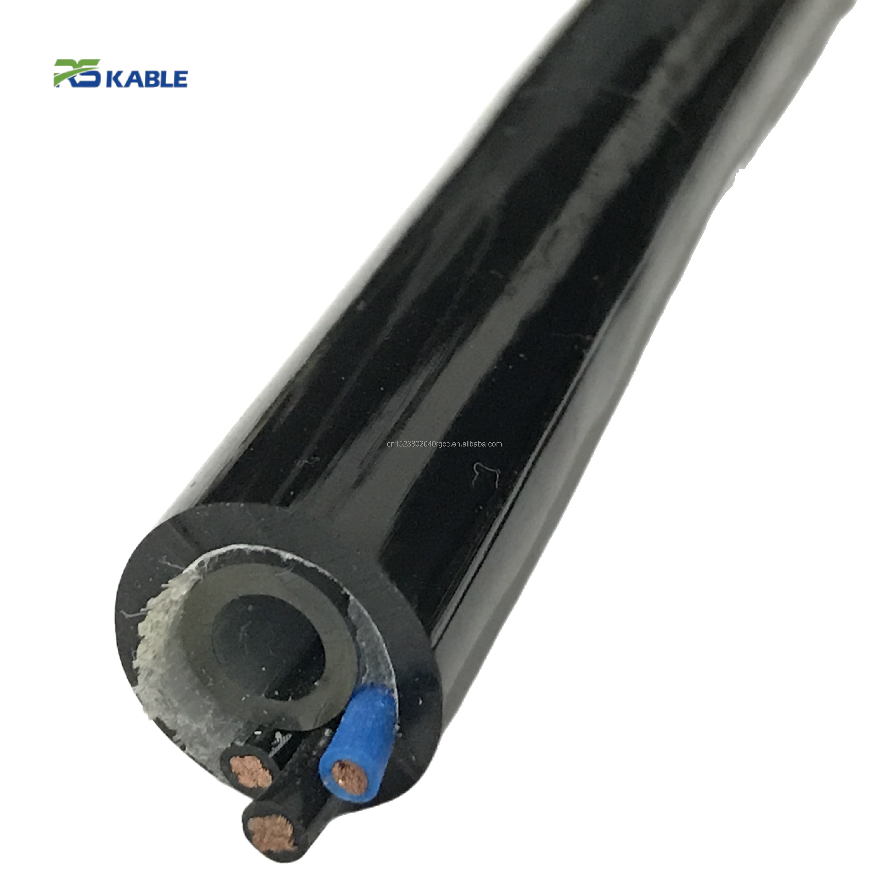
Flexible Pneumatic Tube Composite Cable combines electrical and air line cable in one bundle for robotic grippers and pick-and-place end-effectors. Its matched tube-and-conductor flex design accounts for the tube’s tighter bend radius under pressure, while the braided binding keeps elements in position through repeated joint flexing.
Key Benefits:
✅ Integrated air + electrical bundle eliminates separate hose and cable routing
✅ Pressure-rated bend design prevents tube kinking at flex points
✅ Matched flex life between tube and conductor at the same bend radius
✅ Braided binding prevents internal element shifting under repeated motion
Flexible Pneumatic Tube Composite Cable | Combined Electrical and Air Line Cable for Automation
Application Note — Combined Air/Electrical Supply for Robotic End-Effectors
The mismatch problem nobody specs for on the first try
Bundle a pneumatic tube and an electrical conductor together. Hand the assembly to a design engineer. The natural instinct is to size each element on its own: pick a tube for the air-flow requirement, pick a conductor for the current requirement, sleeve them together, done.
This works right up until the assembly starts flexing at a robot joint. At that point, the two elements almost never fail on the same schedule.
Why the tube usually fails first
PU tube — even good PU tube — has a bend radius limit. That limit is typically tighter than what a fine-strand conductor can tolerate at the same diameter. An assembly sized only against electrical flex-life tables can end up with a conductor rated for millions of cycles, wrapped around a tube that shows wall stress cracking at a fraction of that count. Same bend point, very different lifespans.
The finished assembly’s real service life is set by whichever element is weaker. If nobody checked, that’s usually the tube — discovered the hard way, after installation.
Three questions to check before the electrical spec matters
Before conductor gauge or shielding comes up, three physical questions about the tube determine most of what follows.
Question 1: What’s the bend radius at actual operating pressure?
Published bend radius figures are commonly given at or near atmospheric pressure. A pressurized tube is stiffer. Its effective minimum bend radius is larger than the same tube unpressurized. This distinction matters directly for a joint-flexing application, and it’s easy to miss if the spec sheet number is taken at face value.
Question 2: Where does the tube sit inside the bundle?
A tube on the outer radius of a bend experiences more elongation stress than one near the center. Cross-sectional layout affects which element takes the most cumulative stress over the flex zone — not just which components were chosen.
Question 3: How is the bundle held together?
A loose overwrap lets elements shift position as the assembly flexes. That shift can push a tube toward the outside of the bend over time, putting it through more cycles at a tighter effective radius than the original design intended.
Get these three right, and the electrical side — conductor gauge, shielding, core count — is comparatively straightforward. Get them wrong, and no amount of electrical over-engineering saves a tube that was never going to survive the joint.
Construction
| Element | Detail |
|---|---|
| Pneumatic tube | Polyurethane, sized per required flow rate and pressure |
| Tube pressure rating | Rated at operating pressure, not atmospheric — confirm derating under flex |
| Electrical conductor | Fine-strand tinned copper, IEC 60228 Class 6 |
| Typical conductor cross-section | 0.14 mm² – 0.5 mm² |
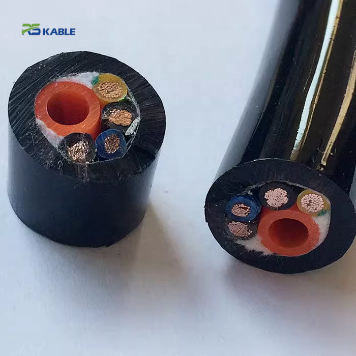
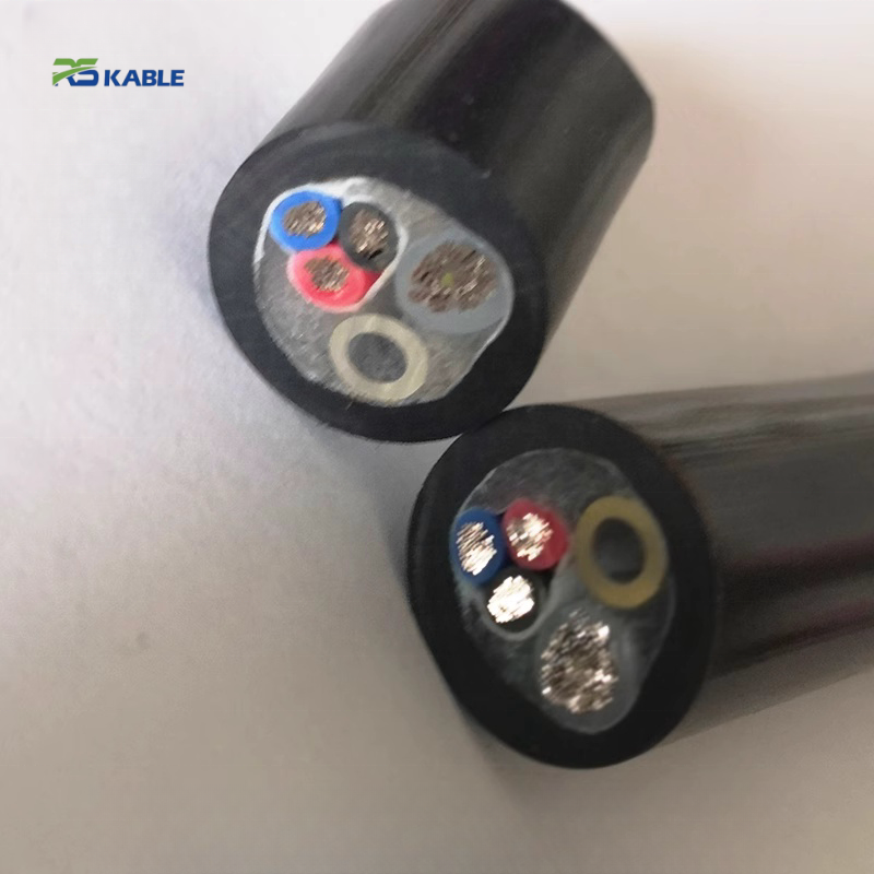
| Bundle layout | Tube position within cross-section selected to reduce elongation stress at flex points |
| Outer binding | Braided overwrap, maintains element position under repeated flex |
| Shielding | Optional, for signal circuits routed near solenoid/motor noise sources |
Configuration is built per application. Tube count, conductor count, and gauge rarely fit a small fixed part list, since pressure, current, and joint geometry differ enough between installations to need at least minor adjustment each time.
A specification walkthrough
A gripper end-effector on an articulated robot arm needs two double-acting pneumatic cylinders and four electrical circuits. That’s four air lines, plus two proximity sensors, one solenoid indicator, and one spare conductor. The assembly routes through the wrist joint, flexing roughly 120 degrees on every pick cycle, several thousand cycles per shift.
Working through the tube side
System pressure runs at 6 bar. The tube manufacturer’s bend radius rating at that pressure — not the unpressurized figure in the general catalog — sets the actual minimum radius the assembly needs at the wrist joint. Checking this against the joint’s real swing geometry showed the tubes needed to sit closer to the bundle’s center. Placing them at the outer edge would have exceeded that radius during full wrist rotation.
Working through the electrical side
Sensor and solenoid indicator circuits draw modest current. Conductor gauge wasn’t the binding constraint here — flex life at the same bend radius the tubes required was. Fine-strand conductors rated for that duty cleared the requirement without needing to be oversized.
The deciding factor
It wasn’t “fit the biggest tube and thickest wire possible.” It was confirming the tube’s pressurized bend rating against real joint geometry first, then building the electrical side to match that already-established flex requirement.
Where a bundled assembly is the right call, and where it isn’t
A combined tube-and-conductor bundle earns its place in three situations: routing space at the joint is genuinely tight, tangle risk between separately routed hose and cable has caused real problems before, or a single connector point at the tooling interface is preferred over two.
It’s the wrong call in two situations. First, when pneumatic pressure exceeds what a joint-flexing tube can reasonably support — high-pressure applications often need thicker-walled tube that doesn’t flex well at tight radii, and separate rigid air line routing outside the flex zone becomes the better answer. Second, when the electrical load includes real power circuits rather than sensor-level signal current. Mixing power conductors and pneumatic tube in one bend-constrained bundle multiplies the cost of getting the tube spec wrong.
Questions that come up before ordering
Our tube spec sheet lists a bend radius, but we’re seeing stress cracking at a radius that should be fine. What’s going on?
Check whether the published figure was rated at atmospheric pressure. A pressurized tube’s effective minimum bend radius is typically larger than the atmospheric-rated figure. This gap is a common source of premature tube failure in flexing installations.
Does tube position within the bundle actually matter?
Yes, more than it might seem at tight bend radii. An element on the outer radius travels a longer path than one near the center. That difference translates directly into more elongation stress per cycle.
Can this handle high-pressure pneumatic circuits, like 10+ bar?
Possibly. Higher pressure typically needs thicker tube walls, which raises the effective bend radius further. At some pressure point, a flexing bundled assembly stops being practical, and rigid line routing outside the flex zone becomes the better solution. This needs checking against the specific pressure and joint geometry involved.
What’s the actual flex-life difference between the tube and a well-specified conductor?
This varies by tube compound, wall thickness, pressure, and conductor stranding — there’s no universal ratio. The practical approach: establish the tube’s flex life at actual operating pressure and bend radius first, then confirm the conductor meets or exceeds that figure.
Do sensor signal circuits in this bundle need shielding?
Only if routed near a noise source — a solenoid coil switching nearby, or a motor drive cable running parallel for some distance. Isolated sensor circuits away from those sources often don’t need it.
Getting a working quote
A few details shorten the quote-to-spec cycle. Operating pressure matters more than flow rate alone. The actual joint geometry and swing angle the bundle routes through matters too. So does electrical circuit count, current draw, and whether any signal circuit runs near a known EMI source. A rough sketch of the joint’s bend geometry — even hand-drawn — resolves more ambiguity than a written description.
[Request a Quotation] · [Ask an Engineer Before You Spec It] · [Download Technical Datasheet]