ROV Cable vs Umbilical: Key Differences for Power, Data, and Handling
A lot of subsea headaches start with one small misunderstanding: calling every line in the water an “umbilical,” or calling every line an “ROV cable,” and assuming the hardware will behave the same. On deck, both can look like “just a tether.” Under load, in current, near structure, during repeated handling—those assumptions get expensive.
This article separates the two in the way operators and engineering teams actually experience them: what changes in power delivery, data stability, and handling behavior, and how those differences should shape your RFQ and acceptance checks.
The simplest way to tell them apart
Forget dictionary definitions for a moment. Think in terms of design intent.
Tether-first (what most teams mean by an ROV tether)
Built to be moved constantly:
-
reeled in and out often
-
bent repeatedly at predictable points
-
managed for low drag and controllable sweep
-
optimized to keep the vehicle “light” and responsive
This is the typical mental model behind an ROV Cable in inspection and survey work.
Multi-utility-first (what most teams mean by an umbilical)
Built to be a robust, integrated service link:
-
more capacity and margin
-
potentially more complex internal build
-
often heavier and stiffer
-
commonly paired with more structured handling infrastructure
Not every umbilical includes fluids, but many are specified with a “multi-service, high-duty” mindset that changes the mechanical feel in the water.
If the mission is precision maneuvering, tether-first thinking usually wins.
If the mission is heavy intervention and integrated services, umbilical-first thinking often wins.
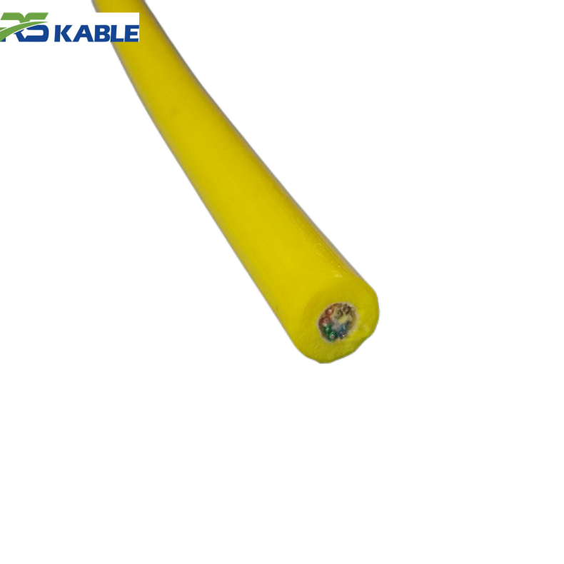
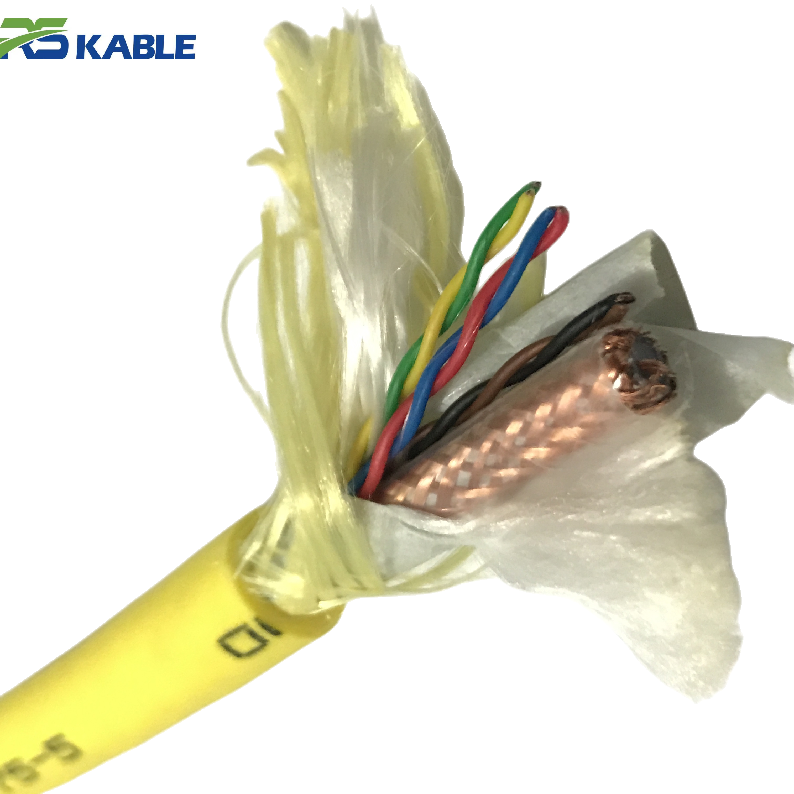
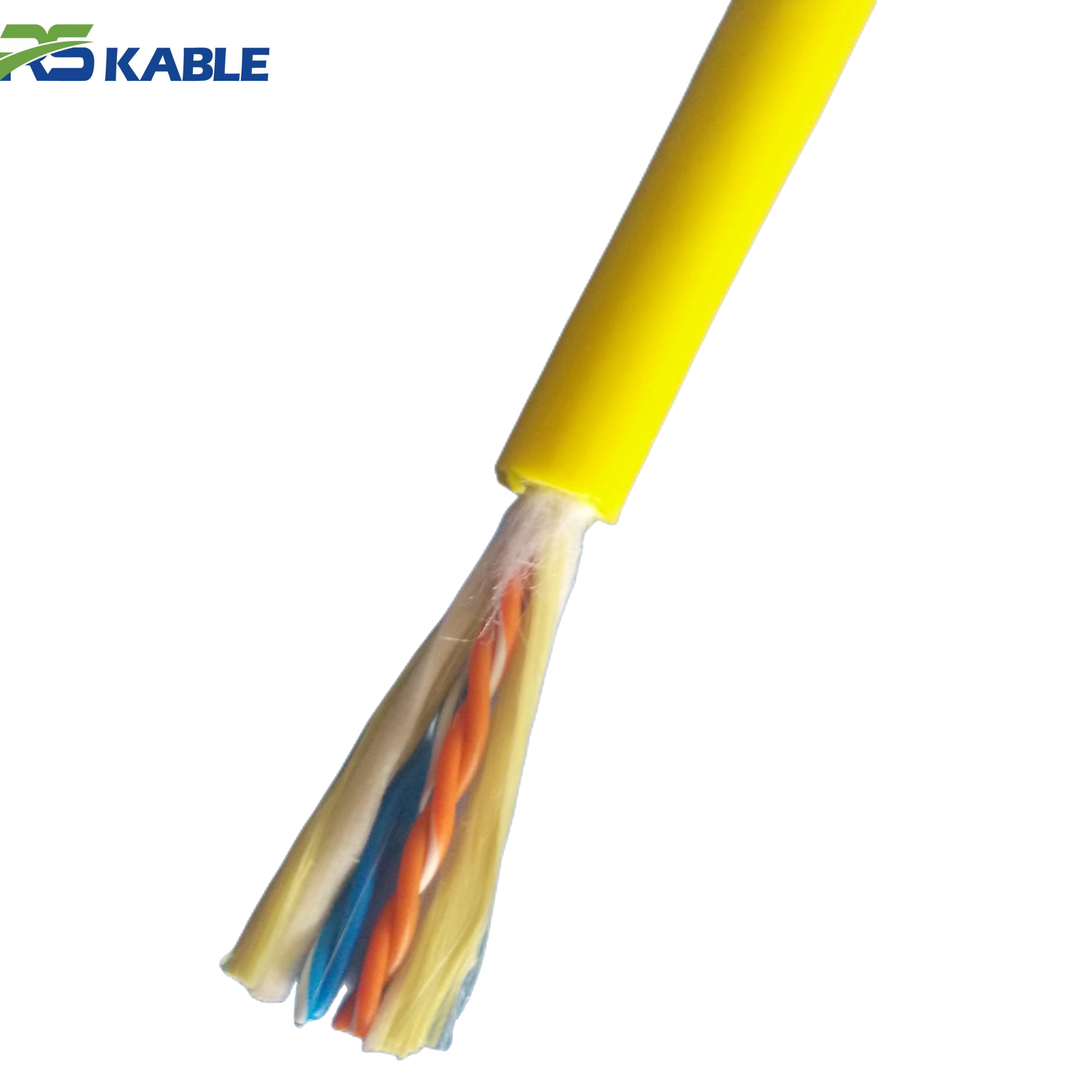
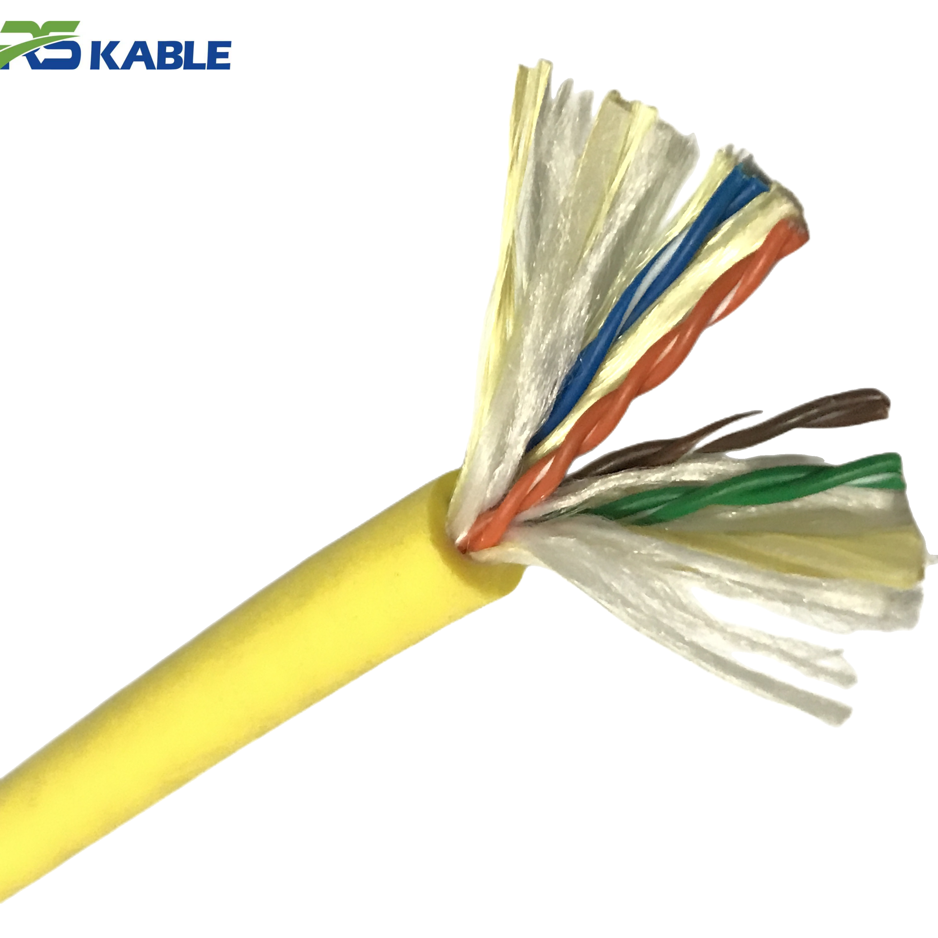
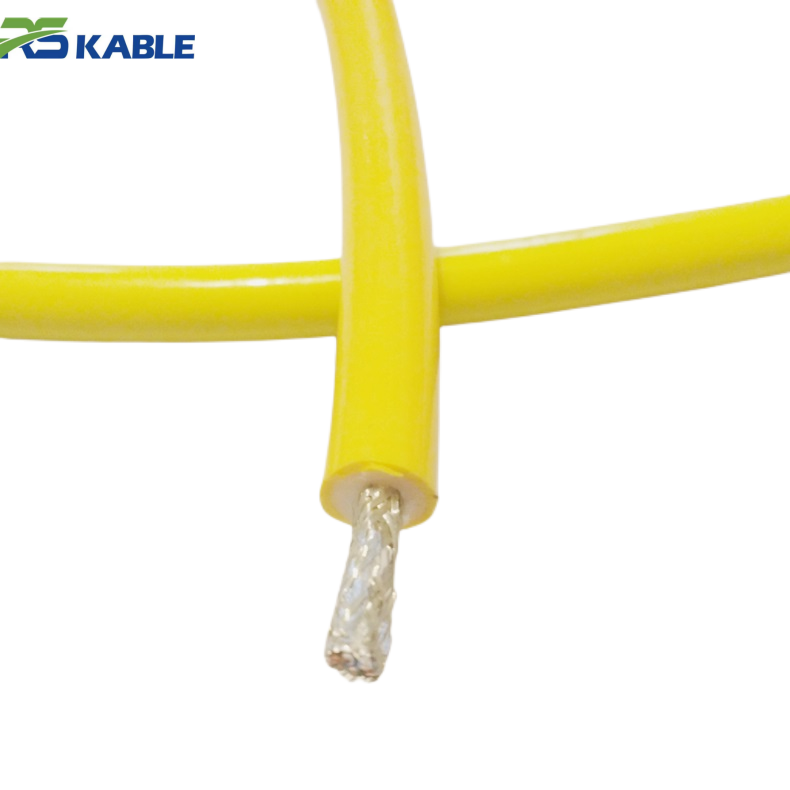
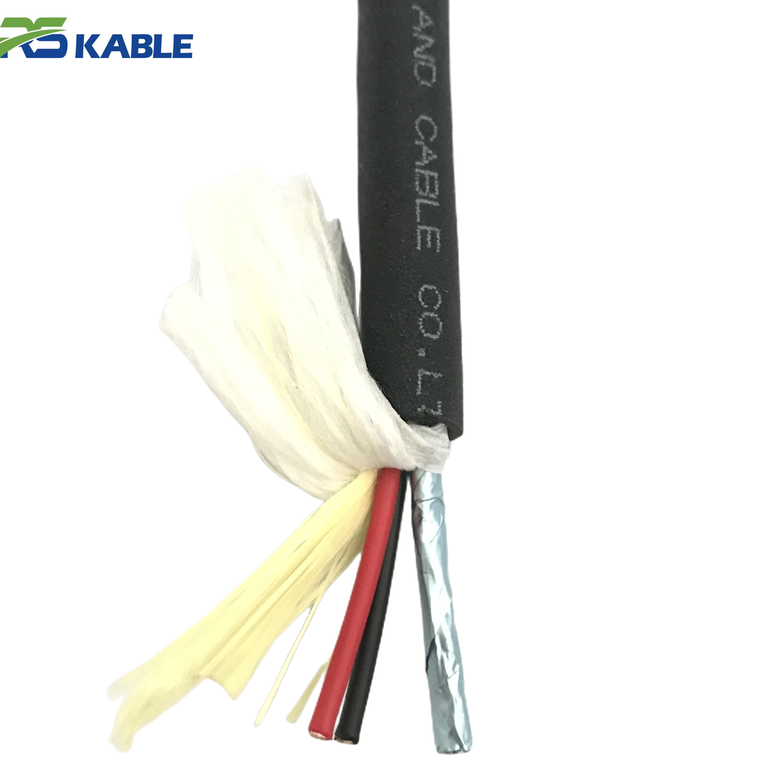
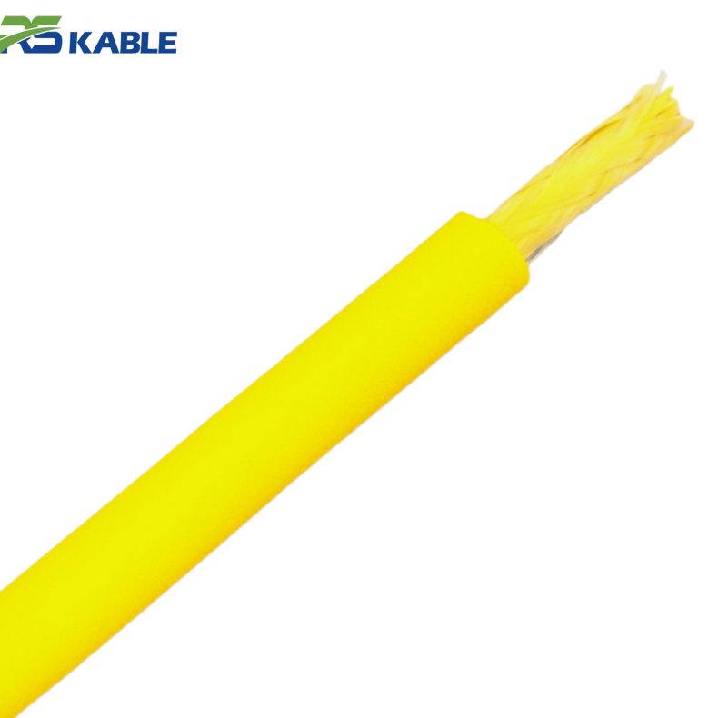
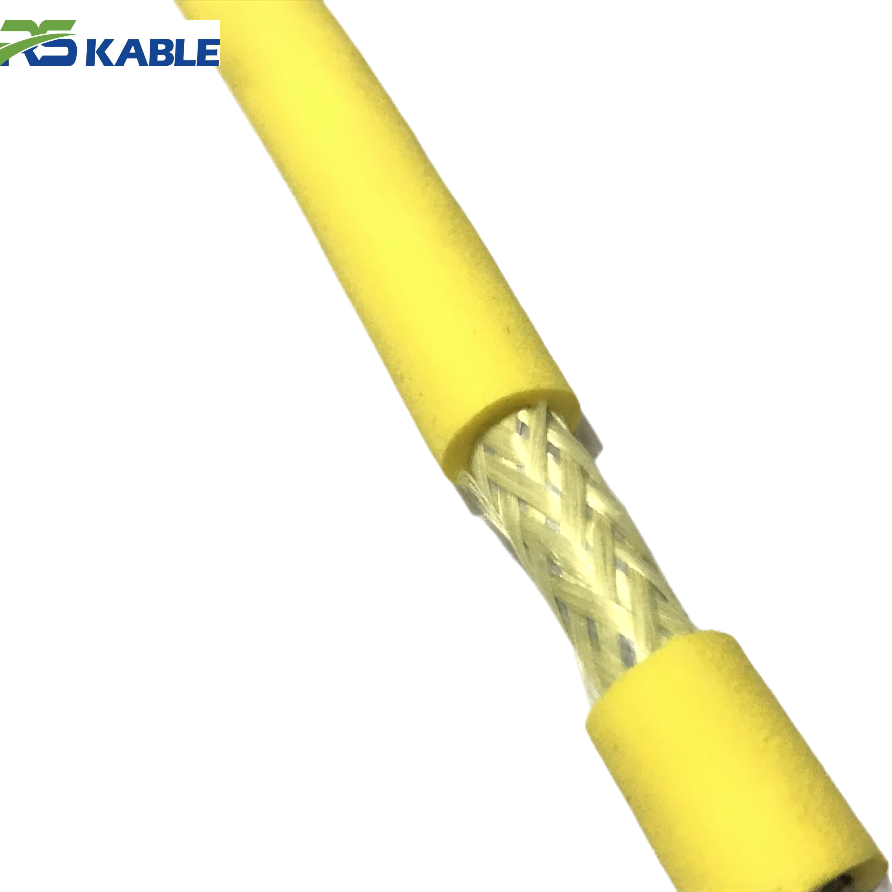
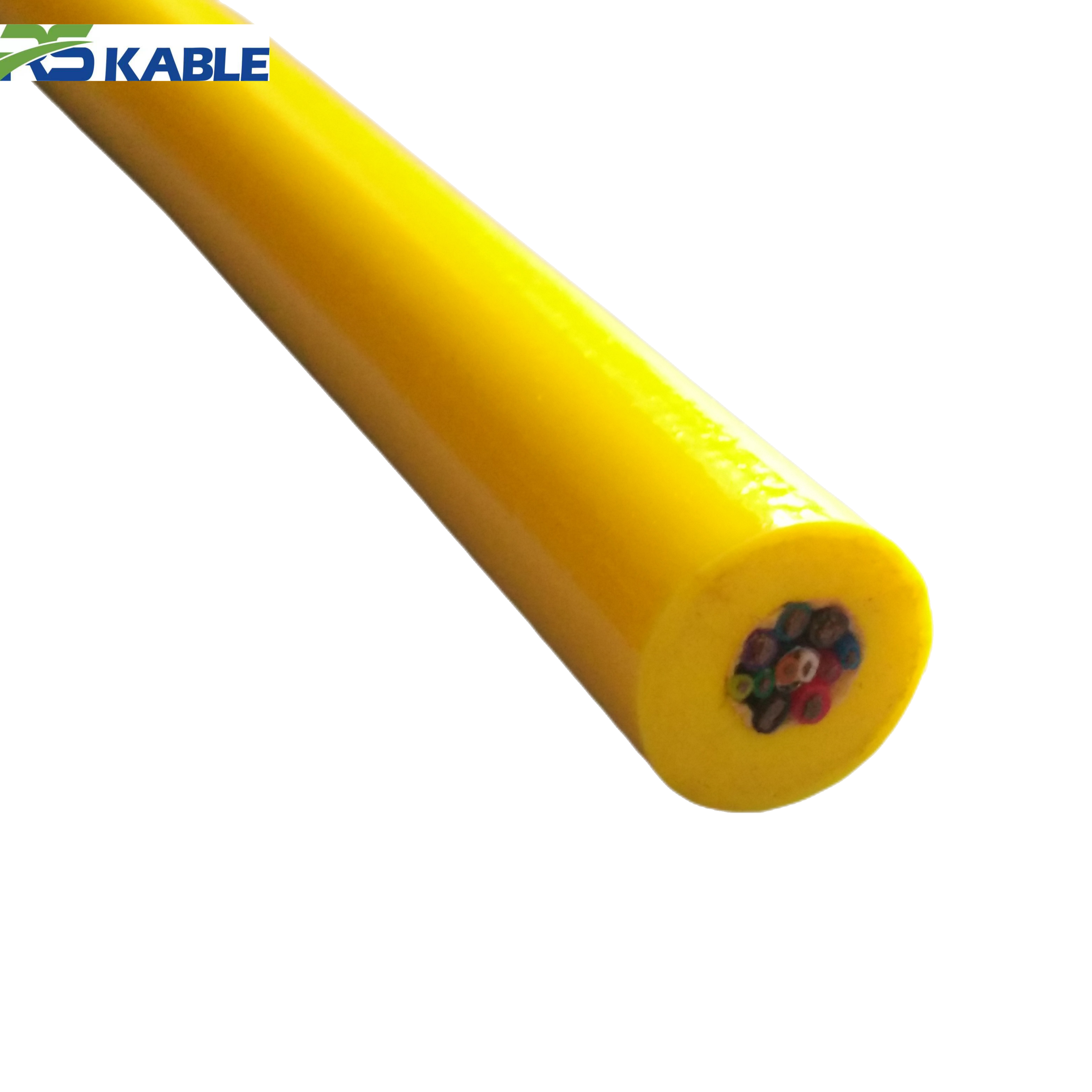
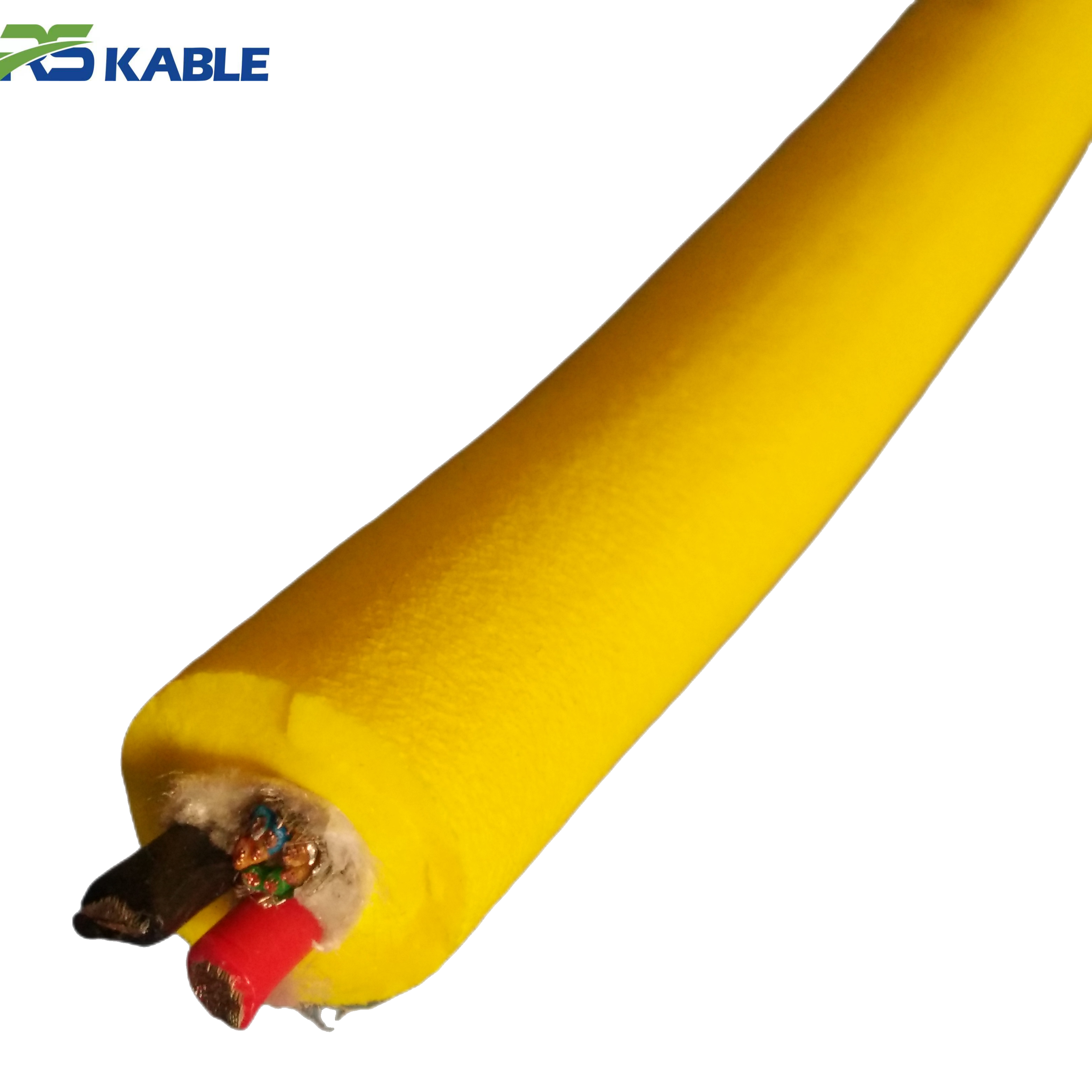
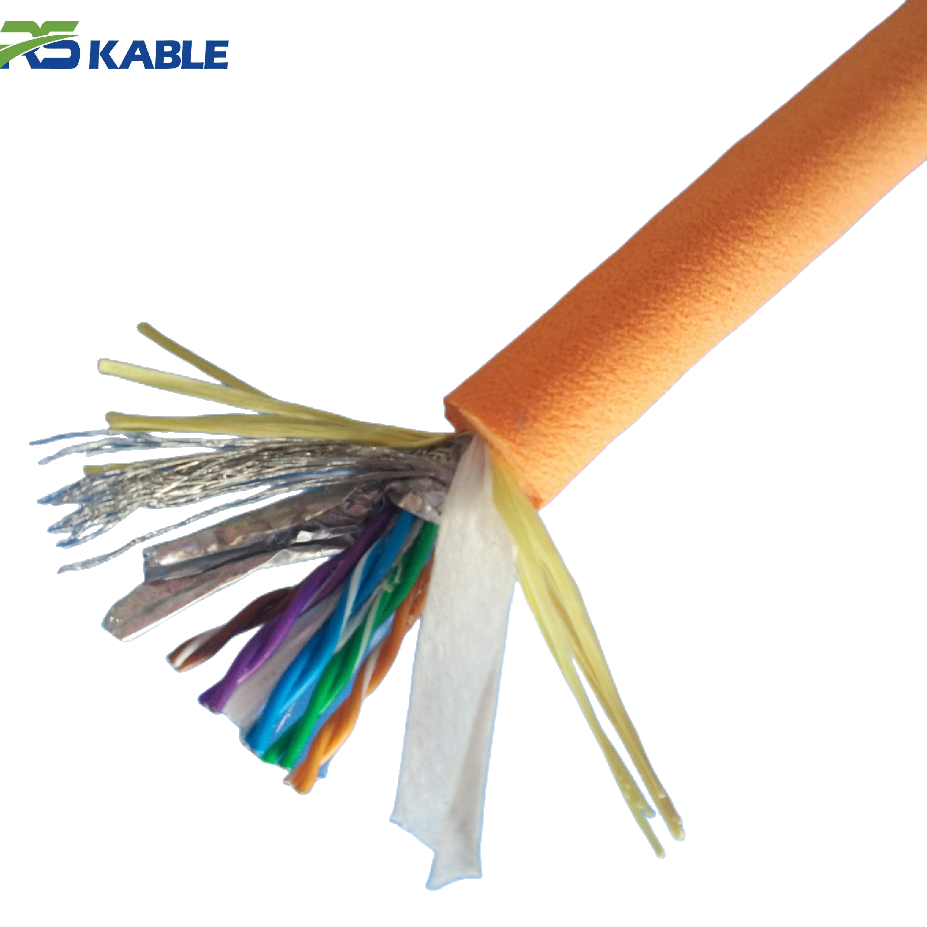
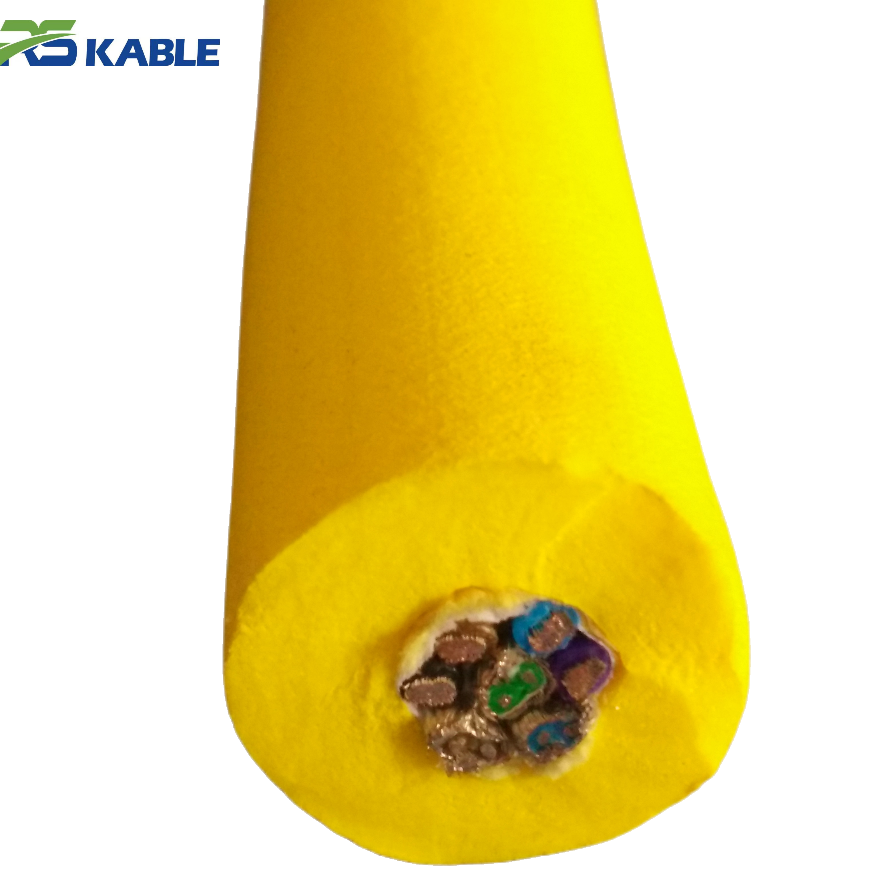
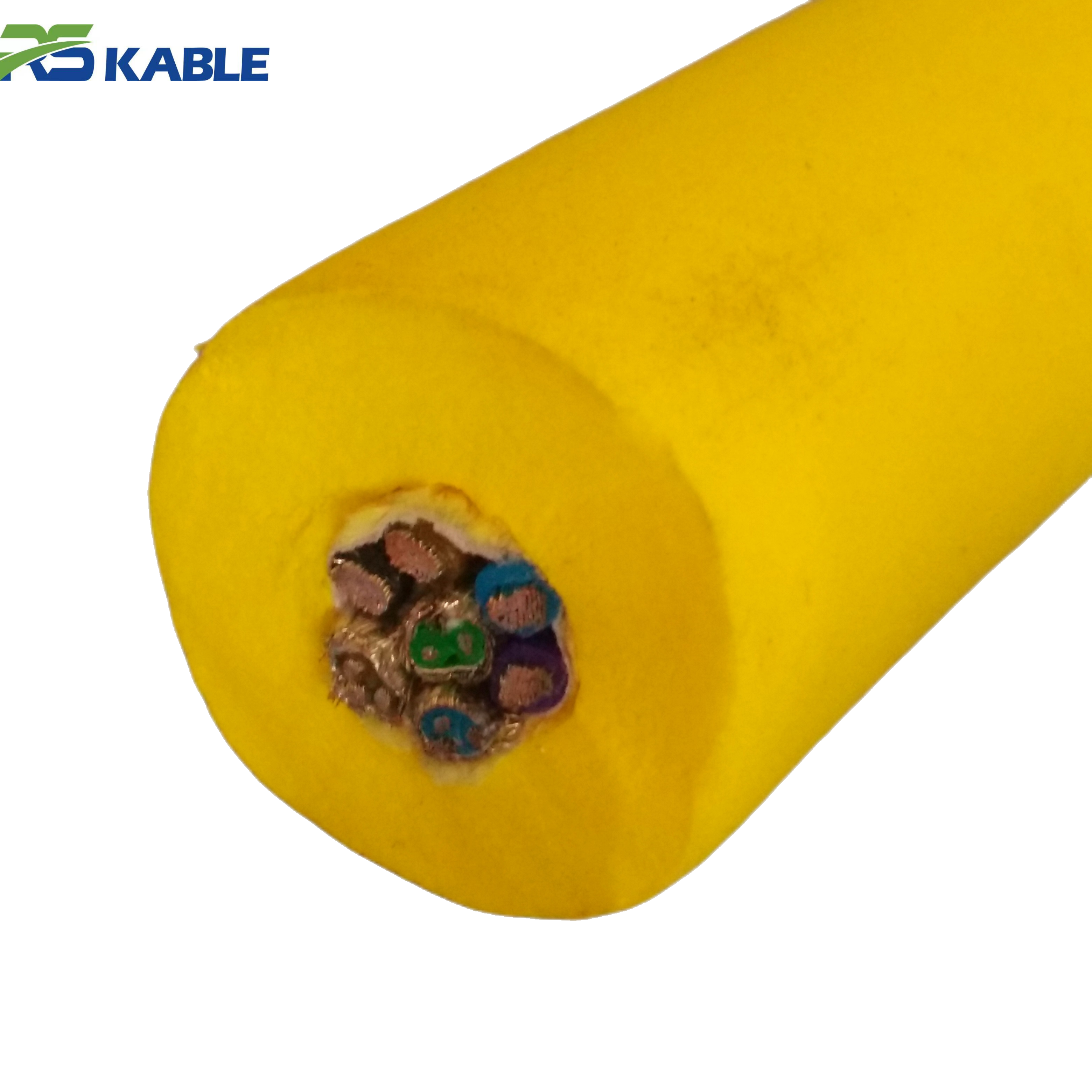
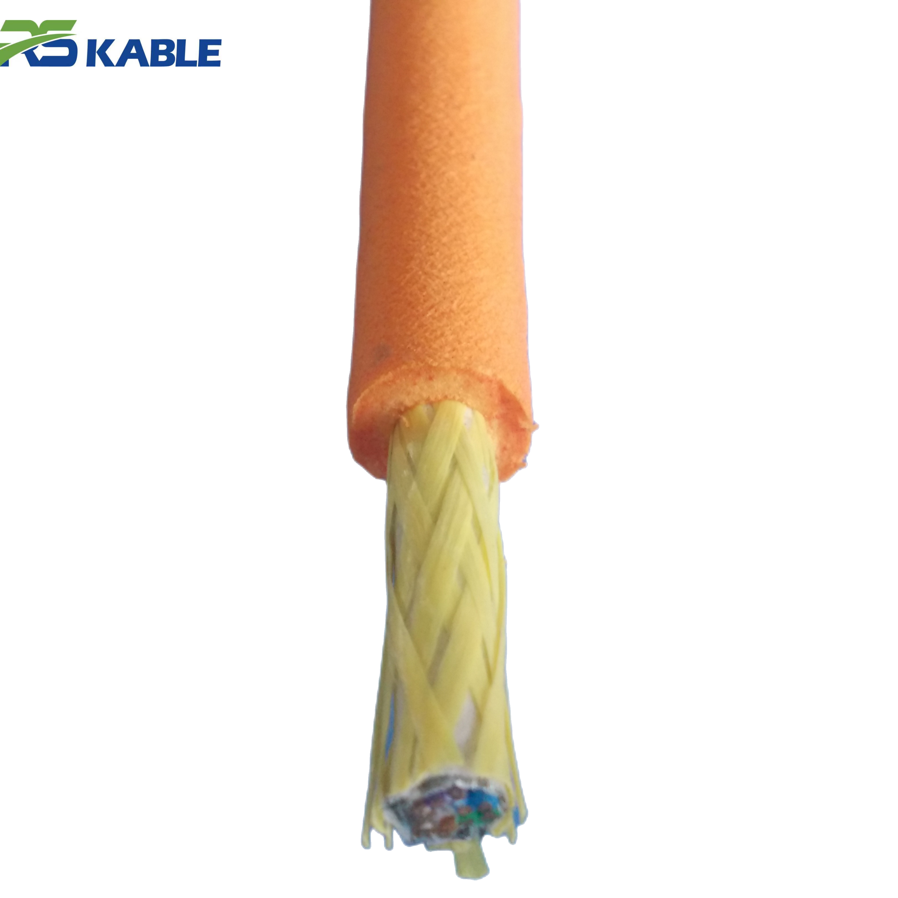
Offshore Construction Projects ROV Cable | Heavy-Duty Jacket & Long-Distance Power Supply
Built for demanding **offshore construction and heavy-duty ROV operations**, this **neutral buoyancy cable** features a robust **heavy-duty jacket** and high-capacity conductors for **long-distance power supply**. It provides exceptional durability against mechanical stress while ensuring precise buoyancy control in deep-sea construction environments.
What changes offshore (the part brochures don’t emphasize)
The true difference shows up in three places:
1) Power under peak load
Many systems look fine at idle. The real test is peak demand:
-
thruster bursts during station-keeping
-
tool starts/stops
-
lighting spikes
-
winch/TMS transitions
Heavier, higher-margin designs can deliver power more comfortably at distance, but the trade is often added diameter and drag.
2) Data stability during movement
Data failures rarely show up during a static dock test. They show up when the line is:
-
bending and unbending repeatedly
-
swept by current
-
routed over sheaves/rollers
-
stressed near the termination
Fiber is common in both styles, but stability depends on integration + termination + bend control, not the label “fiber inside.”
3) Handling behavior in current and near structure
This is where mission efficiency is won or lost:
-
wider sweep zone → more snag risk → slower work
-
heavier sag → more bottom contact → more jacket wear and “sticking”
-
higher drag → more pilot workload → less precision
If your work happens close to seabed assets or structure, handling dominates outcomes more than people expect.
Power: the practical trade between margin and maneuverability
When “more power capacity” helps
An umbilical-style approach makes sense when:
-
sustained power draw is high
-
distances are long
-
you run heavy tooling regularly
-
you need more margin for transients without performance dips
In these cases, prioritizing conductor sizing and power delivery margin can prevent brownouts and unstable tool behavior.
When “more power capacity” quietly hurts
For inspection-heavy work, it’s common to see the opposite problem: the line is overbuilt. Overbuilding often increases:
-
cable OD (drag)
-
stiffness (handling and fatigue hot spots)
-
sweep zone (structure contact risk)
That’s why many inspection teams prefer a tether-first design that meets real power needs while keeping drag manageable. A mission-fit ROV Cable often feels noticeably easier to fly in current even if the headline power capacity is lower.
Practical buying move: specify peak current and working length, then ask suppliers to confirm delivered voltage at the vehicle under that peak load.
Data: it’s not “fiber vs copper,” it’s “what fails in motion”
What typically causes “video drops only when moving”
This pattern is so common it deserves its own line item in your RFQ. It’s usually caused by:
-
strain relief that doesn’t distribute bending stress
-
bend radius violations at routing points
-
micro-bending and fatigue near terminations
-
handling damage that doesn’t show up until the line flexes
The solution is rarely “add more bandwidth.” The solution is mechanical protection of the data path—especially around the first meters behind the connector where stress concentrates.
How to specify data without overspending
Instead of “maximum everything,” define:
-
number of real-time video streams
-
sensor bandwidth requirements
-
latency sensitivity (yes/no)
-
expected future expansion (small margin, not unlimited)
Then require acceptance tests (more on this below). That keeps the design focused and reduces unnecessary diameter growth.
Handling: the deciding factor for inspection missions
If your team spends time near:
-
pipelines and supports
-
frames, valves, risers
-
wrecks, debris fields
-
shallow seabed where contact happens easily
…handling should be treated as a primary requirement, not a secondary benefit.
Why heavier lines snag more often
Entanglement and snags usually come from a combo of:
-
slack loops
-
seabed contact points that “hold” the line
-
current sweep that moves the tether into hazards
Heavier, more negatively buoyant lines collapse slack downward more aggressively, creating bottom loops. Once a loop touches structure, turns and depth changes can tighten that loop into a wrap.
Why diameter matters more than people admit
A small increase in OD can increase drag enough to:
-
widen your sweep zone
-
reduce station-keeping precision
-
force slower passes near structure
-
increase pilot workload
When comparing quotes, OD should be treated like a performance spec, not a cosmetic detail.
Two common spec mistakes and how to avoid them
Mistake 1: Writing “umbilical” when you mean “flexible tether”
This tends to invite heavier constructions by default. If the project is inspection-first, use language like:
-
tether cable / ROV tether
-
dynamic flex duty
-
drag and sweep zone constraints
-
bend radius and fatigue expectations
Suppliers build what you ask for. If you ask for “umbilical” and don’t constrain handling behavior, you may get a line that is technically impressive but operationally slow.
Mistake 2: Only specifying electrical numbers
Electrical compliance doesn’t guarantee mission success. Add mechanical reality to your spec:
-
maximum preferred OD (when current is a factor)
-
minimum bend radius for your handling setup
-
termination strain relief requirements
-
jacket durability matched to seabed hazards
-
buoyancy behavior preference (if relevant)
A “choose the right direction” checklist (no guesswork)
Use these prompts to steer your selection:
Lean tether-first if most of these are true
-
precision inspection is the main work
-
operating near structures is common
-
current makes station-keeping challenging
-
frequent reeling/handling happens
-
efficiency depends on minimizing sweep and snags
-
you don’t need integrated utilities beyond power/data
Lean umbilical-first if most of these are true
-
heavy tooling is frequent and sustained
-
power margin is mission-critical
-
long runs are normal
-
integrated services are required by architecture
-
dedicated handling infrastructure is standard on the project
This is the simplest way to decide the “family” before you argue about details.
What to demand in your RFQ (so quotes are actually comparable)
A short but effective RFQ section should include:
-
Mission type: inspection / survey / intervention
-
Depth: typical and max
-
Current: low / moderate / strong (variable yes/no)
-
Working length: required length + justified buffer
-
Power: operating voltage, peak current, duty cycle
-
Data: fiber count, video streams, bandwidth expectations
-
Handling constraints: maximum preferred OD (if relevant), minimum bend radius
-
Environment: rock/debris/structure density, abrasion risk
-
Terminations: connector type, strain relief expectations, sealing approach
-
Tests required: electrical + fiber + mechanical checks (next section)
If you include these, you’ll get fewer generic quotes and more mission-fit recommendations.
Acceptance & testing: the fastest way to avoid offshore surprises
A line can look perfect on the drum and still waste vessel time. Acceptance checks prevent that.
Electrical (fit-for-purpose)
-
continuity and insulation tests appropriate to your system
-
documentation of results as a baseline for later troubleshooting
-
if practical, a partial-load check to confirm stability under demand
Fiber (when applicable)
-
insertion loss baseline
-
OTDR baseline if your operations use it
-
recorded results stored with the project docs (helps isolate future damage)
Mechanical (the checks most teams skip)
-
confirm the handling setup can maintain minimum bend radius
-
inspect for “hard spots,” kinks, or crushed sections
-
verify termination strain relief is intact and not overly stiff at the connector exit
-
confirm labeling and length marking consistency (basic, but saves time)
These steps are boring—right up until they prevent a failed shift.
A quick reality check using field symptoms
If you’re replacing an existing line, these symptoms point to a mismatch:
-
ROV feels pulled down → line too negative / too much sag / slack strategy wrong
-
frequent jacket scuffing → seabed drag and contact zones too frequent
-
video drops only when moving → termination fatigue / bend radius violations
-
work slows near structure → sweep zone too wide (drag + sag)
-
terminations fail early → strain relief and fatigue design not matched to duty cycle
Fixing these often improves performance more than upgrading the vehicle.
FAQ
Is an ROV cable the same thing as an umbilical?
Not always. In casual speech people mix them, but in specs an “umbilical” often implies broader integration and heavier-duty assumptions.
Which option is better for inspection missions in current?
A tether-first approach is usually better because drag and sweep zone control matter more for precision work near structure.
Can both carry fiber optics?
Yes. The difference is reliability under motion, which depends heavily on termination design, strain relief, and bend control.
Why does a heavier line increase snag risk?
More sag and drag create more contact points. Slack collapses downward more easily, forming bottom loops that catch and wrap.
What should be included in acceptance tests?
Electrical baselines, fiber insertion loss/OTDR baselines (if applicable), and mechanical checks for bend radius and termination strain relief.