ROV Cable Video Dropout: Why It Happens During Movement
ROV cable video dropout during vehicle movement is one of the most disruptive faults in subsea operations. The camera feed is clean at hover. The moment the pilot applies thrust, the image freezes, breaks into blocks, or cuts to black.
This symptom has a specific diagnostic meaning. It tells you that the fault is intermittent and load-dependent. That narrows the root cause to a short list of candidates — all of them addressable without replacing the tether.
This guide walks through every candidate cause in order of likelihood. It gives you a step-by-step isolation procedure and a decision tree to reach the correct repair action without unnecessary cable replacement.
What this article covers:
- Why movement specifically triggers video loss — the four root causes
- How to isolate the fault to cable, connector, vehicle, or surface equipment
- A symptom-to-cause diagnostic table covering 10 common presentations
- Step-by-step repair and adjustment actions for each confirmed cause
- When the fault indicates cable retirement rather than repair
- Six FAQ answers to the most common troubleshooting questions
1. Why Movement Triggers the Fault
A fault that only appears during vehicle movement is an intermittent fault. It is present in the hardware at rest — but the system tolerates it until mechanical stress makes it visible. Understanding which mechanical stresses occur during ROV movement narrows the cause immediately.
Four stresses that occur only during movement
When the ROV moves, four things happen to the tether that do not happen at hover:
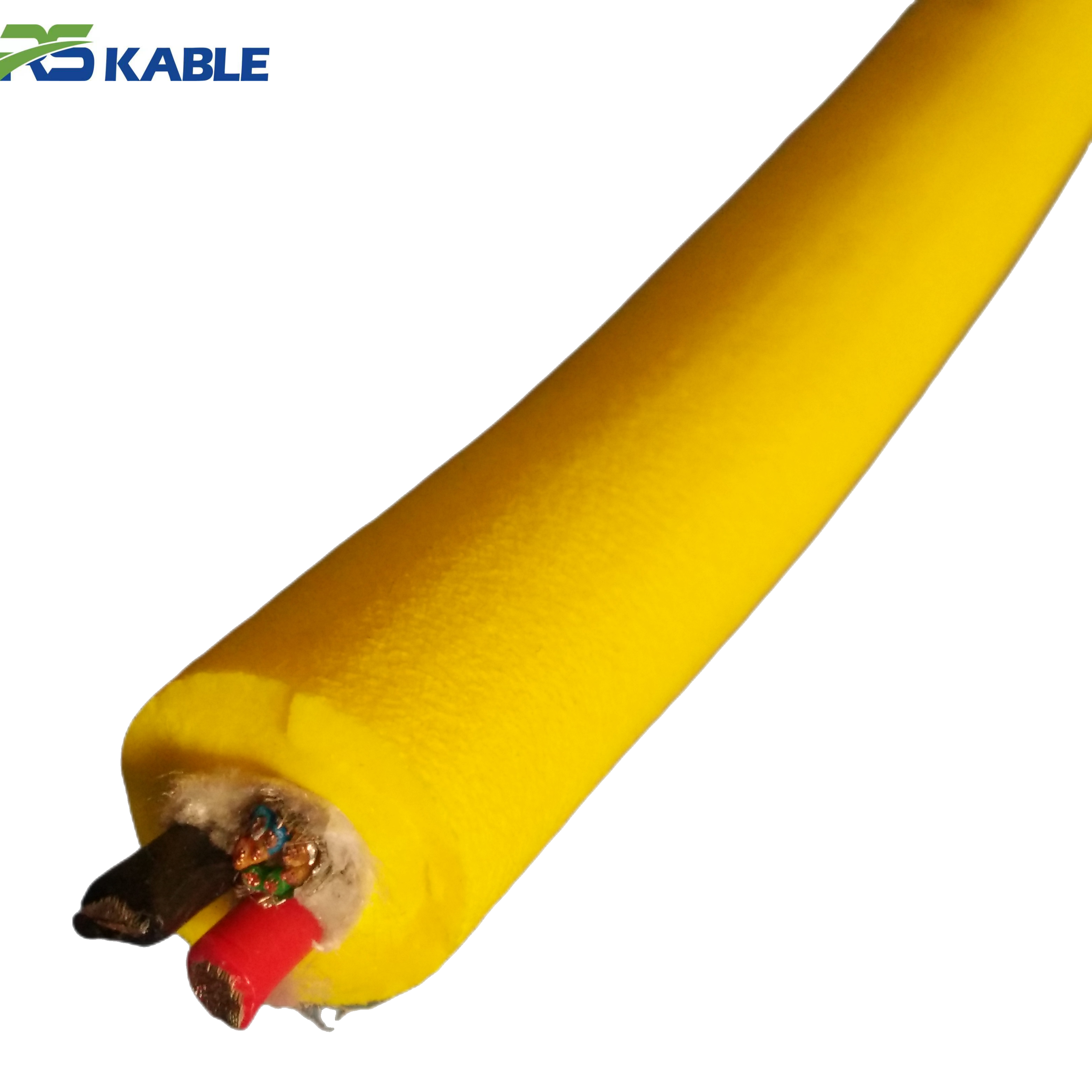
- Tether bending. The cable bends at the deployment point, around fairleads, and near the vehicle umbilical termination. Bending compresses and stretches individual conductors at their inner and outer arcs.
- Tether tension change. Thrust increases tension in the tether. This stretches the cable longitudinally and reduces the cross-sectional area of each conductor slightly.
- Connector movement. Vibration from thrusters transmits through the tether to every connector junction. A connector that seats marginally under static conditions may lose contact intermittently under vibration.
- EMI from thrusters. Thruster motors generate electromagnetic interference when energized. This couples into unshielded or poorly grounded signal conductors running in the same tether.
Each of these stresses points to a different root cause. The diagnostic process works by determining which stress is producing the symptom.
The specific signal path for video
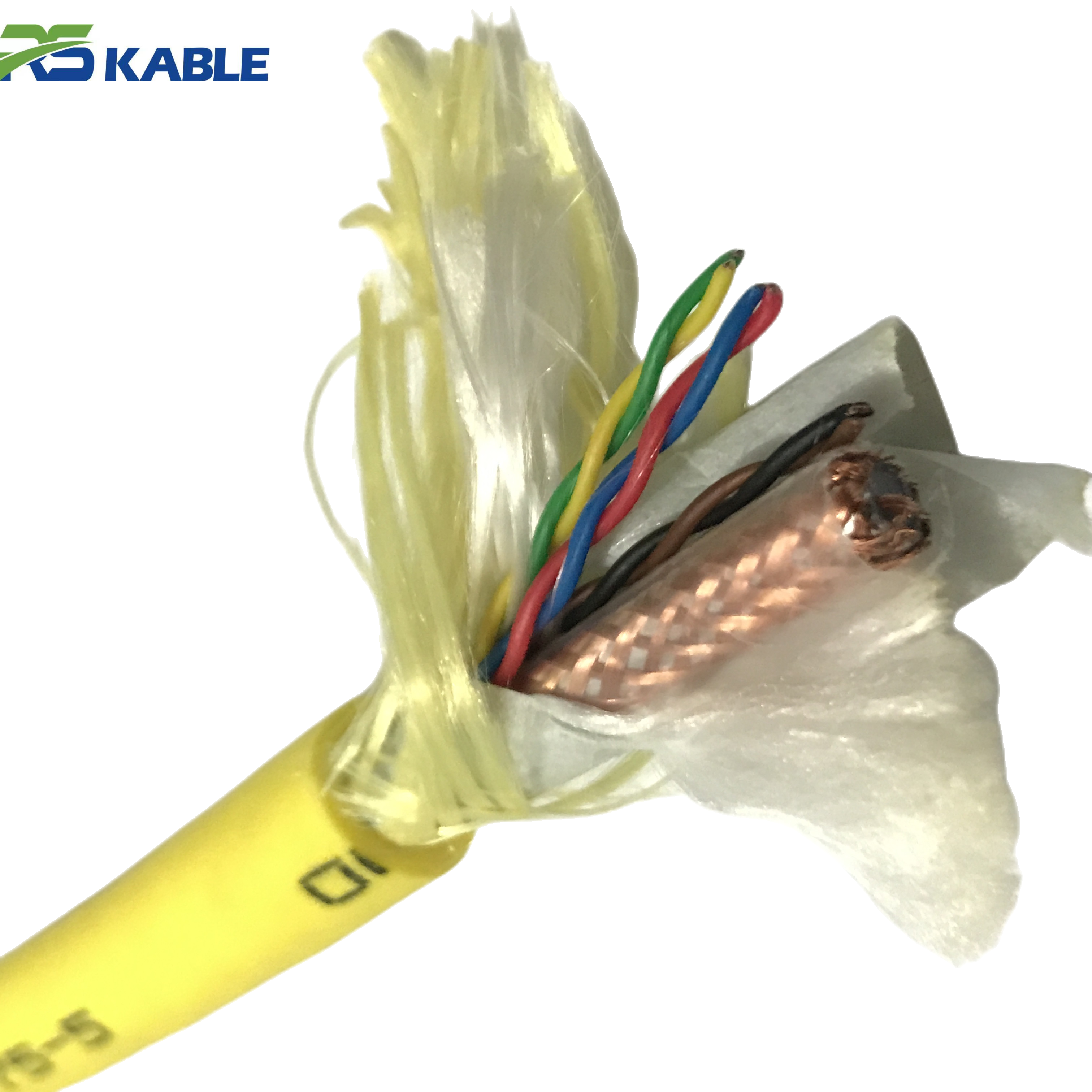
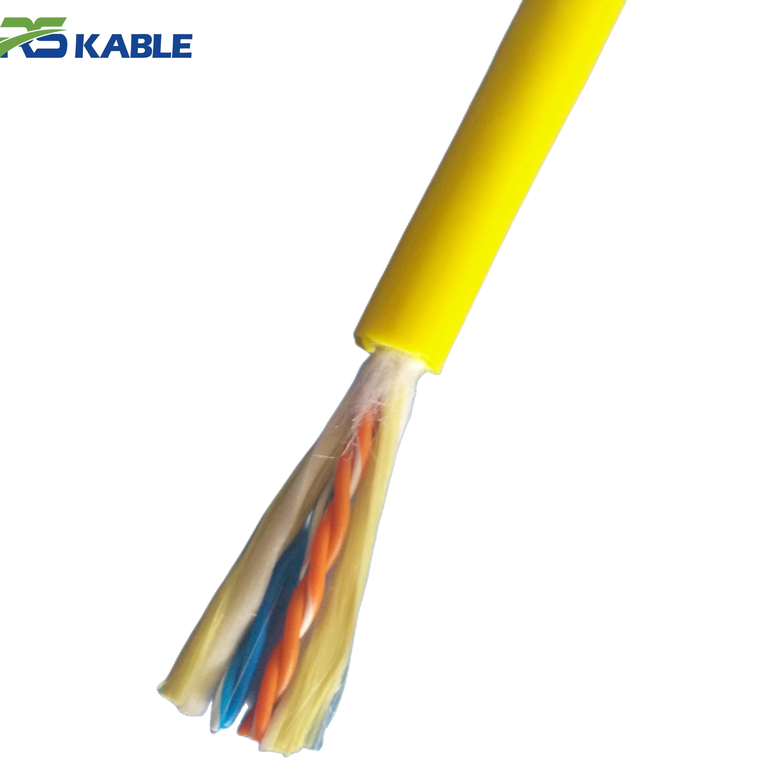
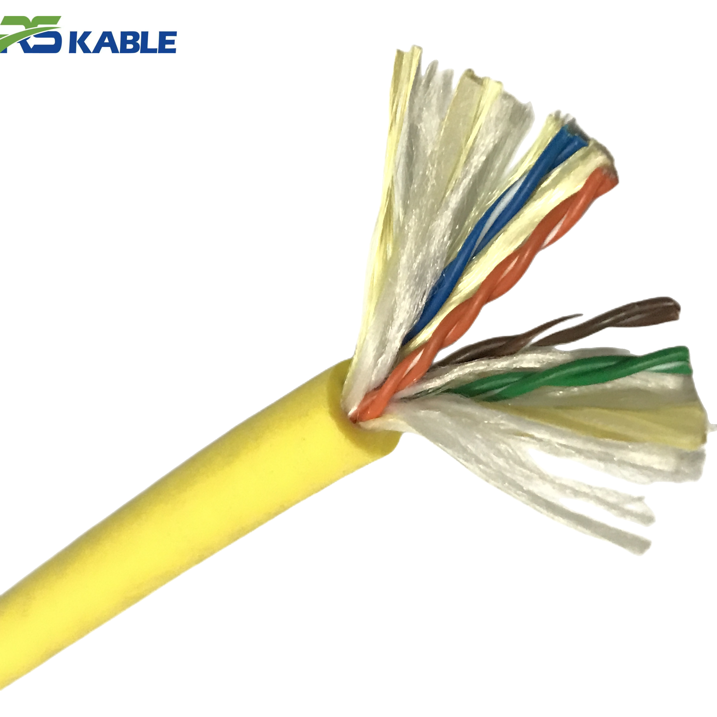
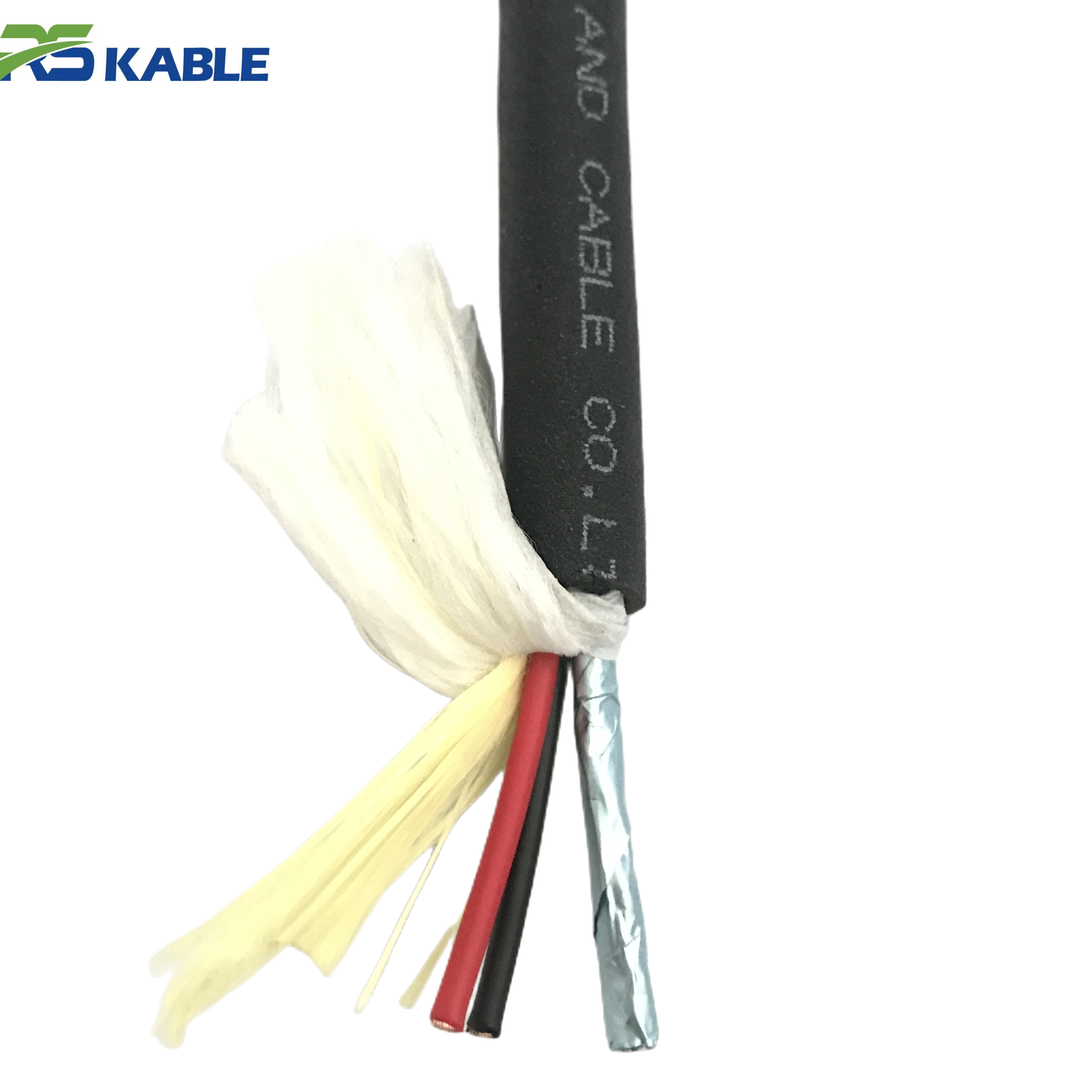
Video signals in ROV tethers travel on one of three conductor types: coaxial cable (analog composite or HD-SDI), shielded twisted pair (IP video over Ethernet), or optical fiber (highest bandwidth, immune to electrical interference).
Coaxial and shielded twisted pair video is vulnerable to all four stresses above. Fiber optic video is immune to EMI and conductor resistance changes — but is vulnerable to bending beyond its minimum bend radius and to physical damage at fiber splice points.
Knowing which conductor type carries your video signal is the first step in any dropout investigation.
Field note: A survey ROV operating in a tidal channel showed clean video at hover but consistent dropout during lateral thrust maneuvers. The operator had spent two days checking the video encoder and decoder before calling us. The fault was EMI coupling from the port thruster into an ungrounded coaxial video conductor. The thruster and video coax ran parallel for 0.8 m inside the vehicle before separating. Re-routing the coax and adding a ferrite choke at the vehicle entry point eliminated the dropout entirely.
2. The Four Root Causes in Detail
Cause 1 — Intermittent conductor fault in the tether
A partially broken conductor strand — caused by bending fatigue, a previous crush event, or kink damage — has full continuity at rest. Under bending stress, the remaining strands separate and resistance spikes. This appears as video dropout because digital video codecs cannot recover from even brief signal interruptions.
This cause produces dropouts at consistent tether positions. The fault location is usually within 2 m of the deployment sheave, the fairlead, or the vehicle umbilical termination — the three highest-stress bending points in the system.
Diagnosis: run a 4-wire resistance measurement on the video conductor pair while an assistant flexes the tether at the suspected location. A resistance spike during flexing confirms the fault and identifies the position.
Cause 2 — Marginal connector contact
Connector pin corrosion or a bent contact pin that maintains continuity under zero vibration can lose contact intermittently when thruster vibration reaches the connector. This produces video dropout that correlates directly with thruster engagement — the signal returns the moment thrust stops.
Marginal connectors often show clean continuity on a standard resistance test. The fault requires testing under vibration or with light mechanical manipulation of the connector body to reproduce.
Diagnosis: with the system powered and video active, gently flex each connector in sequence while monitoring the video feed. The dropout will reproduce when you manipulate the faulty connector.
Cause 3 — EMI from thruster motors
Brushless thruster motors generate significant conducted and radiated EMI when energized. This couples into video signal conductors through two paths: inductive coupling where thruster power conductors run parallel to video signal conductors, and ground loops where the video signal ground and thruster power ground are connected at multiple points in the system.
EMI-induced dropout has a distinctive signature. It appears immediately when any thruster engages — not after a delay — and disappears immediately when thrust stops. The severity correlates with thruster power level, not with tether movement.
Diagnosis: bypass the tether entirely by connecting a short test cable directly from the topside video receiver to the vehicle video output. If the dropout disappears, the tether or its connectors are in the signal path of the EMI. If it persists, the problem is internal to the vehicle.
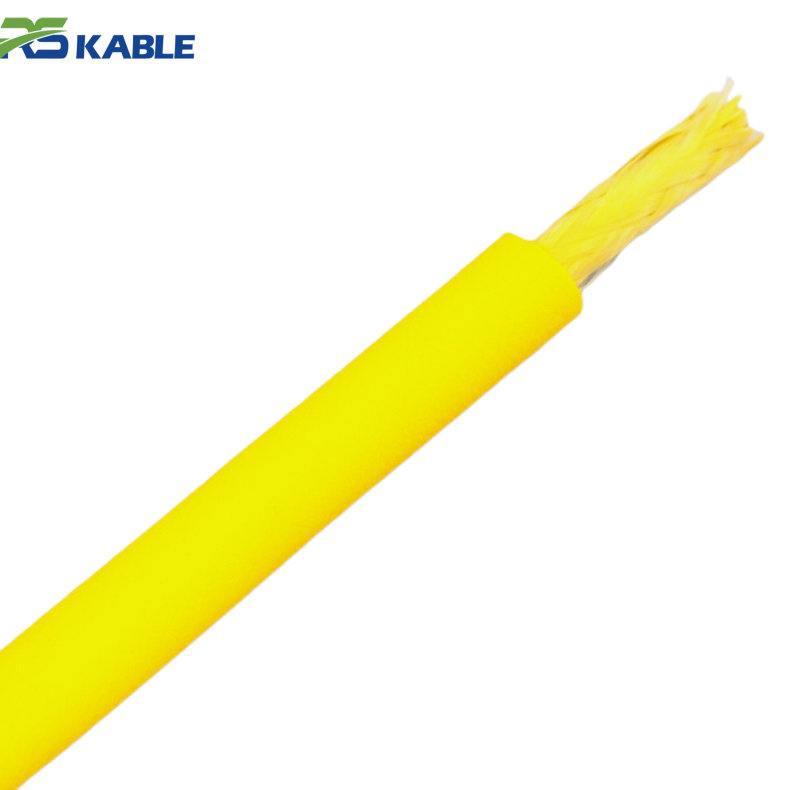
Cause 4 — Fiber bending beyond minimum radius
Fiber optic video conductors in ROV tethers have a minimum bend radius — typically 20–30× the fiber diameter for tight-buffered fiber, or specified in the tether datasheet. If the tether bends beyond this radius at the vehicle umbilical entry point or the topside sheave, the fiber transmission loss increases sharply. At sufficient attenuation, the video signal drops below the receiver threshold.
This cause only applies to fiber-carried video. It produces dropout that is specific to particular vehicle orientations — typically when the vehicle pitches nose-down or yaws to one side, changing the bend angle at the umbilical entry point.
Diagnosis: observe exactly which vehicle orientations trigger the dropout. Reproduce the orientation on the surface with the tether deployed. Measure optical power at the receiver during the fault orientation and compare to the specified minimum receiver threshold.
3. Symptom-to-Cause Diagnostic Table
The following table maps observable symptom characteristics to the most likely root cause. Use it to prioritize your diagnostic sequence before opening any connectors or running electrical tests.
|
Symptom observation |
Most likely cause |
Secondary cause |
First test |
|
Dropout during any thrust, recovers at hover |
EMI from thruster motors |
Marginal connector contact |
Bypass tether test |
|
Dropout at specific tether positions on drum |
Conductor fatigue fault |
Jacket damage at that location |
Flex resistance test |
|
Dropout in specific vehicle orientation only |
Fiber overbend at umbilical entry |
Connector movement at vehicle end |
Optical power meter test |
|
Dropout worsens as tether deploys longer |
Conductor resistance increasing with length |
Digital video signal margin too low |
4-wire resistance measurement |
|
Dropout correlates with thruster power level |
EMI — inductive coupling |
Ground loop in video circuit |
Bypass tether + ground check |
|
Dropout only after 30+ min of operation |
Thermal — conductor heating |
Connector thermal expansion |
IR test hot vs cold |
|
Dropout with physical vibration only, no thrust |
Marginal connector — vibration sensitive |
Loose backshell at termination |
Connector flex test |
|
Dropout starts clean, increases in frequency over days |
Progressive conductor fatigue |
Connector corrosion developing |
Trend IR and resistance tests |
|
Video pixelates but does not fully cut |
Signal attenuation — marginal SNR |
Partial conductor break |
Signal level measurement |
|
Dropout affects one camera, not others |
Single conductor or connector fault |
Camera-specific video encoder fault |
Swap camera connection test |
Table 1. Symptom-to-cause diagnostic matrix. Match your observed symptom to the most likely cause before testing. Multiple symptoms present simultaneously may indicate more than one concurrent fault.
4. Step-by-Step Isolation Procedure
Work through this sequence in order. Stop at the step that reproduces or eliminates the fault. Do not skip steps — the logic of each step depends on the previous result.
Step 1 — Confirm the fault is repeatable
Before testing anything, confirm that the dropout occurs consistently and that you can reproduce it on demand. Note the exact conditions: which thrusters, what movement direction, what tether deployment length, and what depth.
A fault that cannot be reliably reproduced cannot be reliably diagnosed. If the dropout is intermittent and unpredictable, increase your monitoring detail — log the exact time and vehicle state for each occurrence over 3–5 dive cycles before proceeding.
Step 2 — Bypass the tether
Connect the topside video receiver directly to the vehicle video output using a short test cable of the same type as the tether video conductor. Keep the connection as short as possible. Power the system and apply full thrust in the same conditions that trigger the dropout.
If the dropout disappears: the tether or its connectors are in the fault path. Proceed to Step 3.
If the dropout persists: the fault is internal to the vehicle. The tether is not the cause. Diagnose the vehicle’s video encoder, thruster motor controller EMI, and internal cable routing independently.
Step 3 — Isolate tether vs connector
With the tether reconnected, apply thrust at low level while manually flexing each connector body in sequence. Hold each connector for 10 seconds while monitoring the video feed.
If the dropout reproduces during connector manipulation: the fault is a marginal connector. Note which connector and proceed to Section 5, Cause 2 repair actions.
If no connector manipulation reproduces the fault: the fault is in the tether body. Proceed to Step 4.
Step 4 — Locate the conductor fault in the tether body
Perform a 4-wire resistance measurement on the video conductor pair. Have an assistant slowly walk the tether length while applying light lateral flexing pressure with their hands every 30 cm.
Watch the resistance reading continuously. A sudden spike or drop during flexing at a specific location identifies the fault point. Mark the location on the tether with tape. The fault is typically within 0.5 m of the marked point.
If no resistance change is observed during the flex test: the fault is a subtle intermittent that only appears under dynamic bending and tension simultaneously. Proceed to an optical time-domain reflectometer (OTDR) test if fiber is involved, or an impedance analyzer test for coaxial video conductors.
Step 5 — Confirm EMI cause if Steps 2–4 are inconclusive
EMI-induced dropout can pass all static electrical tests. To confirm EMI as the cause, place a current clamp around the thruster power cables and measure the AC component during the dropout event. A significant AC current reading on a DC thruster circuit during the dropout confirms conducted EMI.
Alternatively, connect an oscilloscope to the video signal conductor at the topside receiver input. Apply thrust and observe the signal waveform. EMI coupling will appear as high-frequency noise superimposed on the video signal — visible on the oscilloscope even when the video display shows dropout.
Diagnostic summary: Dropout disappears with tether bypassed → tether or connector fault. | Dropout reproduces during connector manipulation → marginal connector. | Resistance spike during tether flex → conductor fatigue fault at that location. | Dropout persists with all cables bypassed → internal vehicle fault, not tether.
5. Repair Actions by Confirmed Cause
Fixing a marginal connector
Remove the connector and inspect all pins under magnification. Look for corrosion products (white or green powder on copper contacts), bent or recessed pins, and sealing face damage.
Clean corroded pins with the connector manufacturer’s specified cleaning process. Isopropyl alcohol and a cotton swab is acceptable for mild corrosion. Do not use abrasive tools — they remove the contact plating and accelerate future corrosion.
After cleaning, apply the specified dielectric grease to the pin contacts. Mate and un-mate the connector five times to distribute the grease. Retest continuity and perform the connector flex test again to confirm the fault is resolved.
If the pins cannot be brought to specification by cleaning — bent beyond recovery, plating worn through, or sealing face cracked — the connector requires factory retermination. Do not attempt field retermination of subsea wet-mate connectors. The sealing geometry requires factory tooling to meet depth-rated specifications.
Fixing a conductor fatigue fault
A conductor fatigue fault at a localized point in the tether body has two repair paths:
- Fault within 1 m of the end: Cut back the tether to a point 20 cm past the fault. Re-terminate the connector at the new cut end. This is the preferred repair when length allows.
- Fault in the mid-tether body: A mid-body splice repair is technically possible but reduces the dynamic fatigue rating of the tether at the splice point. Treat a spliced tether as suitable for reduced-intensity operations only. Plan for tether replacement within the next maintenance window.
In both cases, re-run the complete pre-deployment electrical test after repair. Confirm the resistance trend is back within 5% of the baseline value before returning the system to service.
Fixing EMI coupling
EMI coupling from thrusters into video conductors has three corrective approaches, applied in order of invasiveness:
- Ferrite chokes. Clip a ferrite toroid choke onto the video conductor at its entry point into the vehicle electronics housing. This suppresses high-frequency conducted noise without any rewiring. It is the fastest fix and often sufficient for moderate EMI coupling.
- Physical re-routing. Increase the physical separation between thruster power conductors and video signal conductors inside the vehicle. A minimum separation of 100 mm reduces inductive coupling significantly. Re-routing requires opening the vehicle electronics housing and is a more invasive procedure.
- Ground loop elimination. If the video signal ground is connected to the thruster power ground at more than one point, a ground loop exists. The fix is to identify and break all but one ground connection in the video signal path. This requires a systematic ground audit of the vehicle’s internal wiring — invasive but permanent.
Fixing fiber overbend dropout
Fiber overbend at the umbilical entry point is corrected by increasing the bend radius at that point. Options include:
- Umbilical strain relief redesign. If the vehicle umbilical entry fitting allows the tether to bend below the minimum fiber radius, replace or modify the strain relief to enforce a larger minimum bend radius. A correctly designed strain relief is the permanent solution.
- Tether management adjustment. If the overbend occurs due to how the tether drapes during specific vehicle orientations, adjust the umbilical attachment point or add a short rigid section at the entry to control the bend geometry.
6. When Video Dropout Indicates Cable Retirement
Signs that repair is not the answer
Not every ROV cable video dropout fault is repairable at reasonable cost. The following conditions indicate that the tether has reached end of service life and should be replaced rather than repaired.
|
Condition |
Implication |
Decision |
|
Multiple fault locations identified in tether body |
Distributed conductor fatigue — cable-wide |
Replace tether |
|
Fault location moves between dive cycles |
Multiple developing fractures — unpredictable |
Replace tether |
|
Fault at mid-tether, spliced but recurring |
Fatigue rate exceeds splice repair rate |
Replace tether |
|
IR declining trend across multiple test sessions |
Distributed insulation degradation |
Replace tether |
|
Fault isolated to connector — single location |
Localized, repairable |
Reterminate connector |
|
Fault at tether end — within 1 m |
Localized, repairable |
Cut back and reterminate |
|
EMI coupling — no conductor damage |
System design issue, not cable failure |
Add choke or re-route conductors |
Table 2. Repair vs retire decision matrix for ROV cable video dropout faults. “Replace tether” means remove from dynamic offshore service. Retired tethers may be suitable for static low-risk applications.
The cost of delaying retirement
A tether with distributed fatigue faults does not fail gradually. It fails suddenly and completely — usually at the worst possible moment. A mid-dive tether failure in deep water means vehicle loss in many cases.
The cost of a new tether — typically USD 8,000–25,000 depending on specification — is always less than the combined cost of vehicle recovery operations, dive program interruption, and client schedule impact from an uncontrolled tether failure.
If the diagnostic process identifies multiple fault locations, or a fault location that cannot be confidently isolated, retire the tether. The risk calculus is straightforward.
7. A Systematic Approach Saves Time and Equipment
Work the logic, not the assumption
The most common mistake in diagnosing ROV cable video dropout is jumping to the most expensive or most visible intervention first. Operators replace tethers when the fault was a corroded connector pin. They replace cameras when the fault was EMI coupling. They rebuild vehicle electronics when the fault was a conductor break 0.3 m from the topside connector.
The isolation procedure in Section 4 is designed to prevent all three of these mistakes. It takes under two hours to complete in full. It identifies the fault location and cause before any repair is attempted. That investment in diagnostic discipline is almost always recovered in the first repair action it prevents.
Log every fault and every fix
Maintain a fault log for each tether. Record every dropout event with date, operating conditions, and the diagnostic result. Record every repair action with the fault location and the method used.
A tether that shows dropout faults at increasing frequency, or at new locations with each event, is telling you that its service life is ending. A fault log makes that trend visible before the tether fails in service. Without a log, the trend is invisible and the failure is a surprise.
Experiencing dropout faults you cannot isolate? Our technical support team provides remote diagnostic assistance for ROV tether faults — including video dropout, signal intermittency, and conductor degradation. Send your fault log, tether specification, and diagnostic test results. We will review and return a written cause assessment and recommended repair action.
Frequently Asked Questions
Q1: Can ROV cable video dropout be caused by the camera itself, not the tether?
Yes — and this is why the bypass test in Step 2 is essential before testing anything in the tether. If the dropout persists when the tether is bypassed with a short test cable, the tether is not the cause. Common camera-side causes of movement-triggered dropout include: thermal stress on the video encoder chip from proximity to thruster heat sinks, loose solder joints on the camera PCB that open under vibration, and camera housing seal failures that allow water ingress into the video circuit. The diagnostic sequence in this article assumes the bypass test has cleared the tether — if it has not, diagnose the camera and video encoder independently before returning to tether diagnostics.
Q2: Why does the fault only appear at depth and not during surface tests?
Depth introduces three conditions that are absent at the surface. First, hydrostatic pressure compresses the tether jacket and slightly reduces the cable’s outer diameter — changing the bending stiffness and increasing stress concentration at any existing conductor damage point. Second, low temperature at depth increases the stiffness of polyurethane jacket compounds, which changes the bending load distribution in the cable. Third, the full tether length is deployed at depth, which increases the resistance of long conductor runs and reduces the signal-to-noise margin for digital video. A fault that the system tolerates at short tether length may exceed the video receiver’s threshold at full deployment depth. Run all diagnostic tests at operational depth when possible.
Q3: How do I know if the dropout is from EMI or from a conductor fault?
The timing of the dropout relative to thruster engagement is the clearest distinguishing characteristic. EMI-induced dropout appears immediately when a thruster motor is energized — within the first half-second of thrust. It disappears immediately when thrust stops. Conductor fault dropout has a slight delay — the fault opens under bending stress, which takes a moment to develop as the tether loads up. It may also persist briefly after thrust stops, while the tether returns to its rest geometry. A second distinguishing test: apply thrust while the tether is slack on the deck surface with no bending stress. EMI coupling will still cause dropout because the thruster motor is running. A conductor fault will not cause dropout because the cable is not being bent.
Q4: The dropout affects all cameras simultaneously. Does this change the diagnosis?
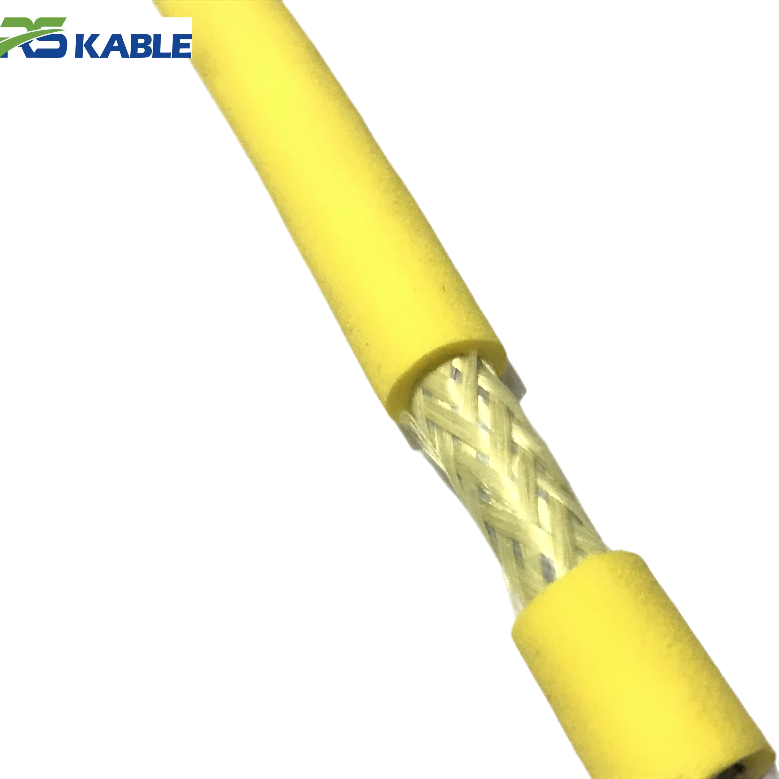
Yes — significantly. A fault that affects all video feeds simultaneously points to a shared path in the signal circuit. This is most likely a common ground reference fault, a shared power rail issue affecting all video encoders, or EMI coupling into the common video bus inside the vehicle rather than into individual conductors. It is less likely to be a tether conductor fault, because individual conductor faults affect only the conductors directly involved. Start the diagnostic sequence with the bypass test, then check the vehicle’s common video ground connection and the power supply to the video electronics. If the dropout affects all feeds and the bypass test clears it, check the tether’s overall screen continuity — a broken outer screen allows EMI to couple into all conductors simultaneously.
Q5: My dropout is intermittent over days, not during every dive. How do I diagnose it?
Intermittent faults that occur over days rather than within a single dive are usually developing faults — a conductor that is progressing toward full failure, a connector that is corroding slowly, or a seal that is allowing gradual water ingress into the cable body. The diagnostic approach is to trend your electrical test results across multiple test sessions. Run an insulation resistance test and a conductor resistance measurement before every dive for two weeks. Plot the results. A degrading conductor will show a gradual resistance increase. A water-ingress fault will show a declining insulation resistance reading. The trend tells you the cause and gives you advance warning of imminent failure — which is far better than waiting for the fault to become consistent enough to isolate by the standard diagnostic sequence.
Q6: Can I use a cable locator or TDR to find the fault location without flexing the entire tether?
A time-domain reflectometer (TDR) can locate impedance discontinuities in coaxial video conductors and in the tether’s power conductors. It works by sending a test pulse down the conductor and measuring the time for a reflection to return — the reflection time corresponds to a physical distance. TDR is most effective for locating open-circuit or short-circuit faults. It is less effective for intermittent high-resistance faults that only open under mechanical stress, because the fault must be open during the measurement for the reflection to occur. For intermittent faults, the manual flex test with a resistance meter remains more reliable. Use TDR as a complement to the flex test — to confirm the location after the flex test has identified the approximate region — rather than as a replacement for it.