ROV Cable Types Explained: Power, Fiber Optic, and Hybrid Designs
Most teams don’t choose an ROV tether because they love cable catalogs. They choose one because the job demands it—and because the wrong choice shows up fast: the vehicle feels heavy in current, the tether drags and scuffs, video drops only during movement, or a termination fails in the middle of a shift.
This guide explains the three mainstream tether architectures used in ROV work—power, fiber optic, and hybrid power + fiber—but it does so in a field-forward way: how each type behaves in water, what typically fails first, and how to confirm you’ve received what you specified. If you need a practical answer to “which ROV cable type fits my mission,” this is written for that decision.
The three ROV cable architectures in one sentence each
Power cable: built to deliver electrical power efficiently over the required working length.
Fiber optic cable: built to keep video/telemetry stable at bandwidth levels copper struggles with.
Hybrid cable: built to do both—power and fiber—inside one tether that must still handle well.
Those sentences are simple; the real differences appear in behavior and failure patterns.

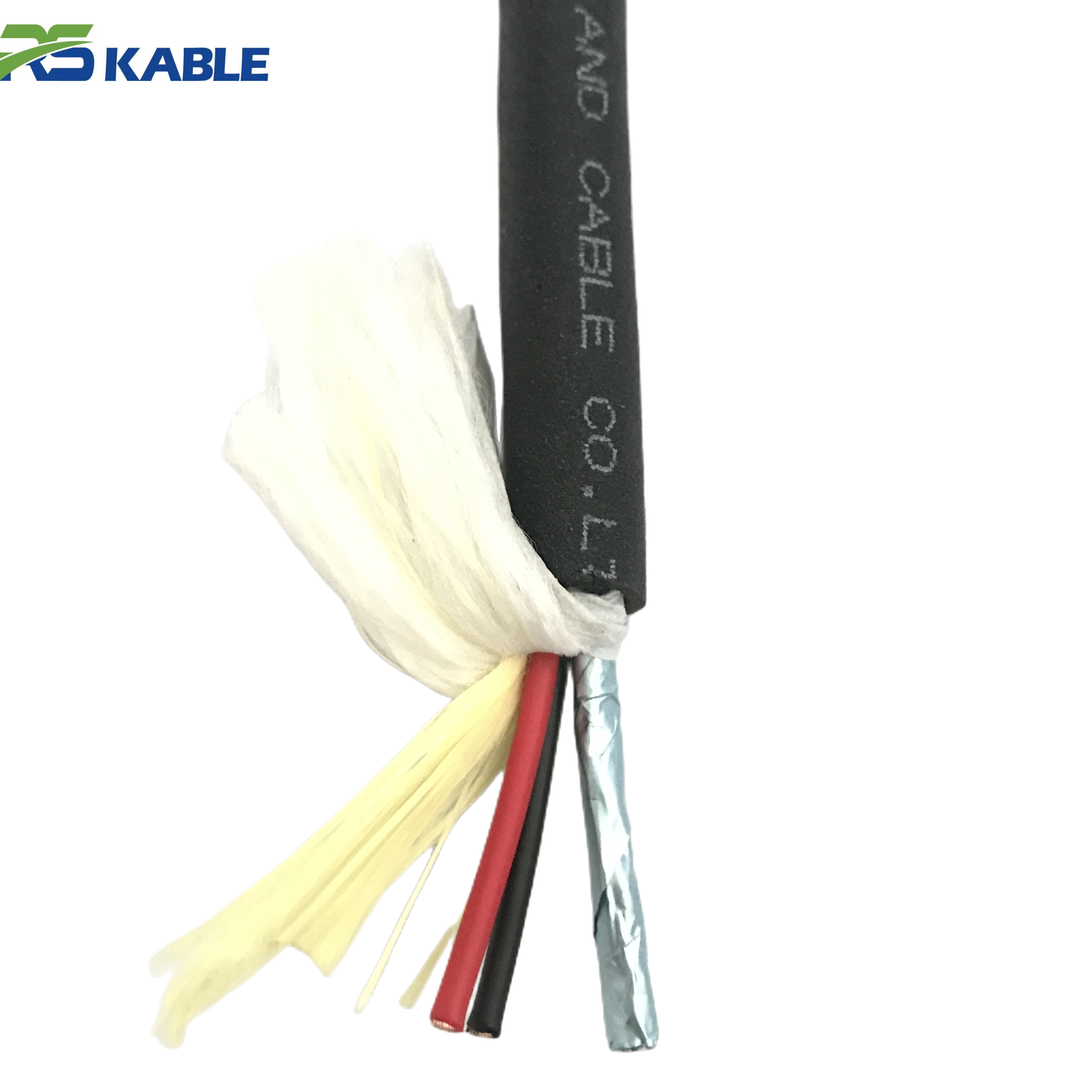
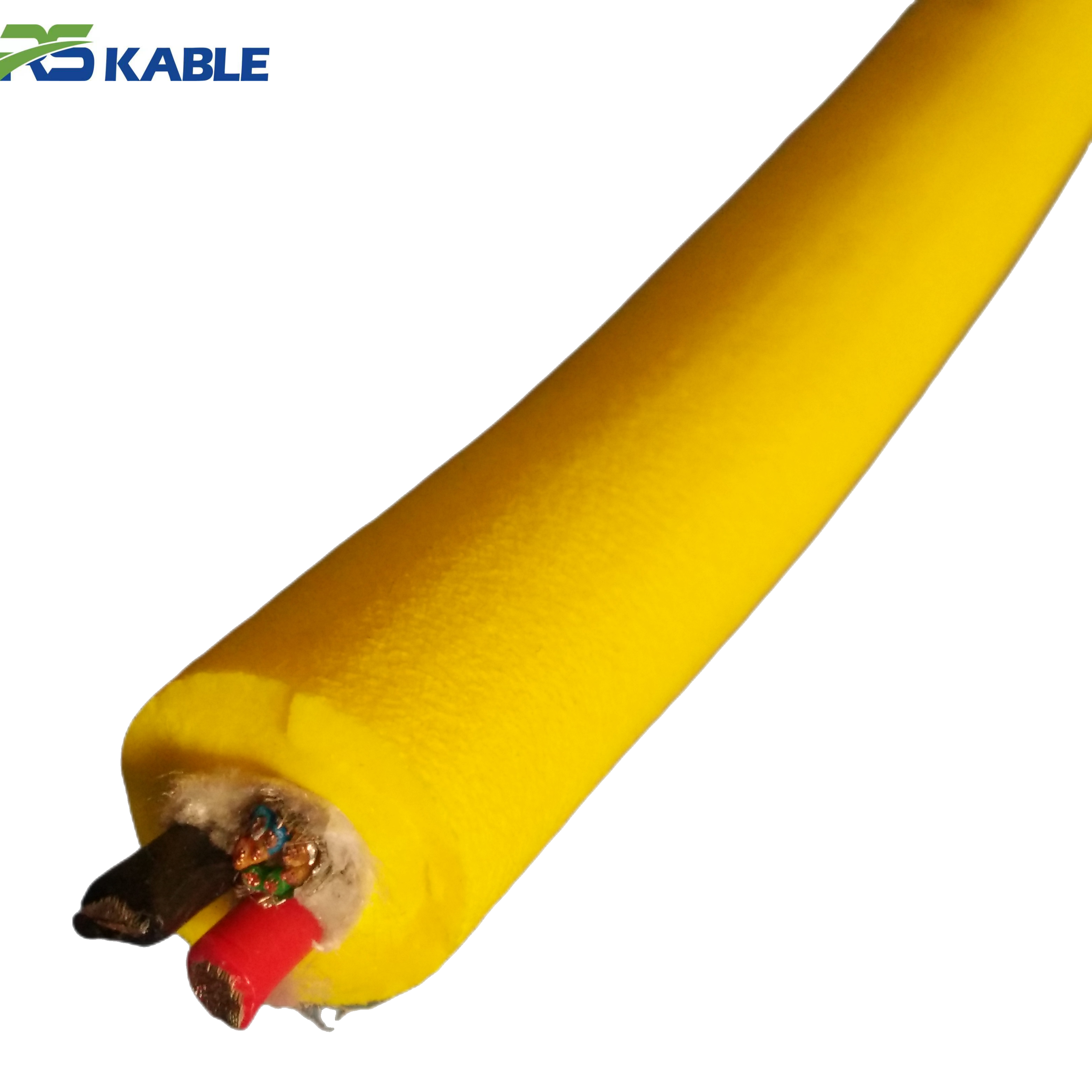
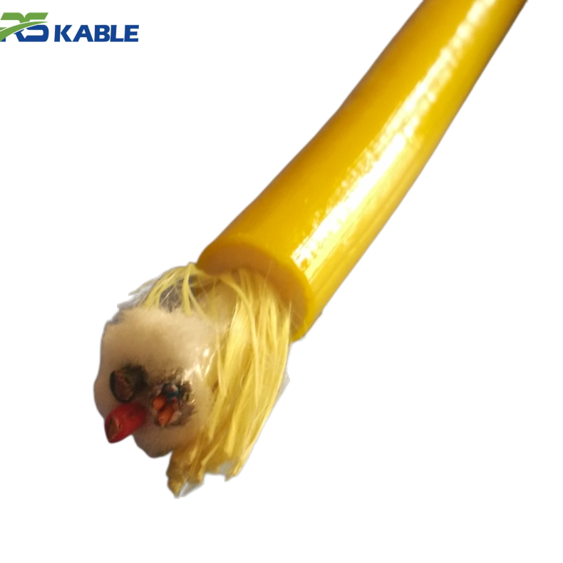
Subsea Pipeline Inspection ROV Cable | High Tensile Strength & Superior Pressure Resistance
Specially designed for **subsea pipeline inspection and long-range ROV missions**, this **neutral buoyancy cable** offers exceptional **high tensile strength** and **pressure resistance**. It ensures stable power delivery and high-fidelity signal transmission while navigating through deep-sea pipelines and hazardous underwater infrastructures.
Choose by mission stress, not by “type”
Before selecting a tether architecture, classify your job using four stress factors. These decide which type is safest and most efficient.
-
Power stress: Are you running heavy tooling or sustained thruster load?
-
Data stress: Is live high-quality video/sonar/telemetry essential, and how many streams?
-
Handling stress: Are you in strong current, shallow water, or tight structure zones?
-
Lifecycle stress: How many reel cycles and bend events happen per shift/week?
If handling stress is high, diameter, buoyancy behavior, and fatigue design can matter more than “extra capacity.”
Type 1: Power-focused ROV cable
Where it fits best
Power-focused tethers make sense when the job is power-driven and data demands are modest, or when data is handled through a different architecture. Typical scenarios include:
-
shorter working lengths
-
simpler inspection setups
-
missions where video requirements are limited
-
systems with low complexity payloads
What it’s good at
-
straightforward electrical design
-
cost-effective for simpler missions
-
easier to specify when your main variable is load and length
What typically goes wrong
Power tethers often fail operationally in two ways:
A) Peak-load voltage drop
The tether meets rated voltage but doesn’t deliver stable voltage under bursts: thrusters + tools + lights. The symptom is performance softness under load—reduced thrust margin, tool brownouts, or unexplained resets.
B) Termination heat and fatigue
When conductors are undersized for real duty cycle, terminations heat and age faster. When the cable is repeatedly bent at the same point, fatigue shows up first near the connector—not mid-span.
When to avoid: If your project is video-heavy, sensor-heavy, or relies on stable real-time data, a pure power tether is often a short-term solution.
Type 2: Fiber optic ROV cable
Where it fits best
Fiber-first designs are a strong match when the mission is driven by data quality and stability:
-
high-resolution video inspection
-
multi-sensor payloads (sonar, advanced imaging)
-
long working lengths where copper data becomes fragile
-
environments with electrical noise where copper signals get unstable
What it’s good at
-
stable bandwidth headroom for modern inspection workflows
-
improved noise immunity for data paths
-
cleaner scaling when you add sensors later
What typically goes wrong (and why it’s often misdiagnosed)
Fiber problems often show up as:
-
video dropouts only when the vehicle moves
-
intermittent telemetry flicker under maneuvering
-
“works on the dock, fails offshore” behavior
This usually points to micro-bending stress and termination strain relief, not to “bad fiber.” Fiber tolerates a lot when bend limits and strain relief are respected; it becomes unforgiving when the system repeatedly flexes below the safe radius at the same point.
Field clue: If data is stable while stationary and unstable while moving, the failure is usually mechanical (bend/fatigue near terminations) rather than bandwidth.
Type 3: Hybrid power + fiber ROV cable
Hybrid is the most common modern architecture because it matches how ROV missions actually run: you need real power and reliable real-time data in one line.
Where it fits best
-
inspection missions that also use tools or high lighting loads
-
longer runs where both voltage stability and data stability matter
-
operations that expect future sensor expansion
-
teams that want one tether to simplify deck handling
What it’s good at
-
one line to manage for power and data
-
supports modern video-centric workflows
-
scalable for payload upgrades without re-architecting the system
The trade that matters most: diameter and drag
Hybrid builds can easily become overbuilt. Overbuilding increases OD and stiffness, which increases drag and sweep zone in current. That can slow work near structures even if electrical specs look great.
Hybrid succeeds when the designer balances:
-
conductor sizing for peak load
-
fiber protection for dynamic bending
-
diameter control to reduce drag
-
fatigue design near terminations
The handling reality: how cable type affects mission speed
Cable type influences how the tether behaves in three ways that impact efficiency:
1) Drag and sweep zone
Larger OD increases drag, especially in current. Drag expands the sweep zone behind the vehicle and makes close work slower and riskier.
2) In-water behavior (sag vs loop tendency)
A tether that sags heavily drags the seabed and “sticks” during turns; a tether that rises too much can loop and cross. Controlled behavior reduces snag risk and pilot workload.
3) Fatigue concentration
ROV tethers don’t usually fail randomly. They fail where the same bend happens repeatedly: near termination exits, at routing points, and at handling hardware.
For many teams, handling improvements do more for productivity than adding extra electrical capacity.
A practical selection rule-set (fast decisions)
Use this as a quick filter:
Choose power-focused when:
-
your data needs are simple
-
working length is short to moderate
-
peak load planning is straightforward
-
cost and simplicity matter more than expansion
Choose fiber-focused when:
-
real-time data quality is the mission
-
multiple streams/sensors must stay stable
-
you need noise immunity
-
power is managed separately
Choose hybrid when:
-
the mission needs both meaningful power and real-time data
-
you want one tether for operational simplicity
-
you expect future sensors or camera upgrades
-
you can control diameter/drag in the design
“Failure signature” cheat sheet (what you see vs what it usually means)
Video drops only during movement → strain relief/fatigue/bend radius issue near termination
Tether scuffs in the same area quickly → catenary too low (sag), slack strategy, or drag-driven seabed contact
ROV feels pulled down → in-water weight too high or too much slack creating sag
Work slows near structures → sweep zone too wide (often OD/drag issue)
Terminations fail early → repetitive bending concentrated at one point; termination design mismatch
These are selection clues as much as troubleshooting clues.
What to put in an RFQ so suppliers can’t “guess wrong”
A strong RFQ eliminates ambiguity:
-
Mission type: inspection / survey / intervention
-
Working length and maximum deployed length
-
Depth range and current profile
-
Power: operating voltage, peak current, duty cycle
-
Data: number of live video streams, sensor bandwidth, fiber count
-
Maximum preferred OD (especially if current is significant)
-
Tensile rating target and safety margin expectations
-
Minimum bend radius requirement based on your handling setup
-
Jacket requirements: abrasion/cut risk description
-
Termination interface and strain relief expectations
-
Acceptance tests required (next section)
This prevents the common outcome: a technically impressive tether that handles poorly for the mission.
Acceptance tests that prevent offshore surprises
A cable is not “ready” just because it arrived.
Electrical baseline
-
continuity and insulation checks appropriate to your voltage class
-
record results as a troubleshooting baseline
Fiber baseline (if fiber exists)
-
insertion loss baseline
-
OTDR baseline if your operations use it
-
record baseline data before first deployment
Mechanical/handling checks (the most overlooked)
-
confirm your routing respects minimum bend radius
-
inspect for local hard spots, kinks, crushed areas
-
inspect termination strain relief: ensure no sharp stiffness transition at connector exit
-
verify labeling and length marking consistency
These steps reduce “mystery problems” that waste vessel time.
FAQ
Is hybrid always the best choice?
No. Hybrid is common because many missions need both power and data, but it can be overbuilt and draggy if OD isn’t controlled.
Why does fiber fail “only when moving”?
Because the issue is usually mechanical—strain relief, bend radius violations, or repeated micro-bending near terminations—not bandwidth.
How do I avoid an overbuilt hybrid tether?
Specify maximum preferred OD, define peak load accurately, and require termination fatigue design plus acceptance tests.
What cable type is best for strong currents?
The one with controlled diameter/drag and predictable handling. An oversized tether can underperform even with excellent electrical specs.
What should I test before first deployment?
Electrical continuity/insulation baselines, fiber insertion loss baselines (and OTDR if used), plus bend radius and termination strain relief checks.