ROV Cable Tensile Strength Guide: Load Ratings, Safety Margin, and Real-World Use
A tensile number on a spec sheet doesn’t stop downtime. What stops downtime is understanding when peak loads happen, where load transfers fail, and how to build margin without making the tether so large and stiff that it becomes a control problem in current.
This guide is written as a practical field reference for selecting and managing tether strength. It explains load ratings, how to set safety margins by scenario, why terminations determine real strength, and what to verify before the first deployment. The goal is a reliable, controllable ROV Cable that survives the worst realistic day—not just a calm-water demo.
Three short stories that explain most tensile failures
Case 1: “The cable never broke—until recovery”
A tether ran all day without issue. During recovery, the vessel rolled, the lead angle shifted at the fairlead, and tension spiked for a few seconds. The cable body survived. The termination didn’t.
Lesson: peak tensile events often occur during recovery, and the termination is frequently the limiting component.
Case 2: “A minor snag became a major load event”
The ROV brushed a structure; the tether caught lightly. The vehicle continued to pull while the cable was held. Tension rose quickly, then released suddenly when the snag cleared. The next dive showed intermittent faults near the end.
Lesson: snag spikes and shock tightening can damage the termination zone even if nothing “looks broken.”
Case 3: “It was strong, but it made the job slower”
A project overbuilt tensile capacity. OD and stiffness increased. In current, drag and sweep zone widened, causing more contact and more conservative piloting. The tether didn’t fail—but productivity dropped and snag risk increased.
Lesson: strength without controllability can reduce safety and efficiency.
These three patterns cover a large share of real-world tether problems.
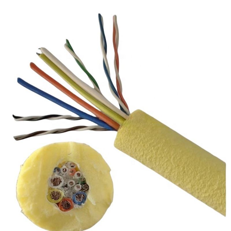
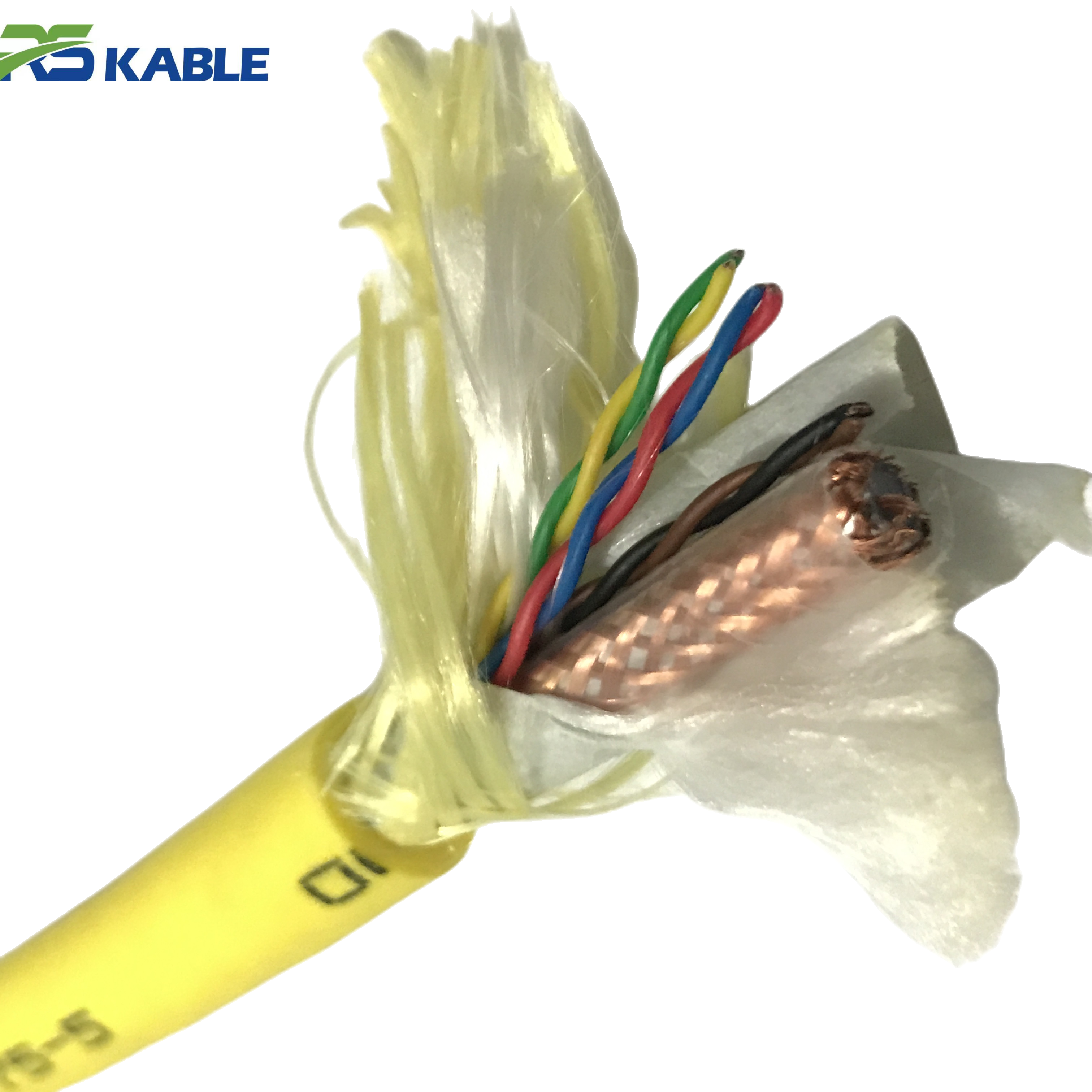
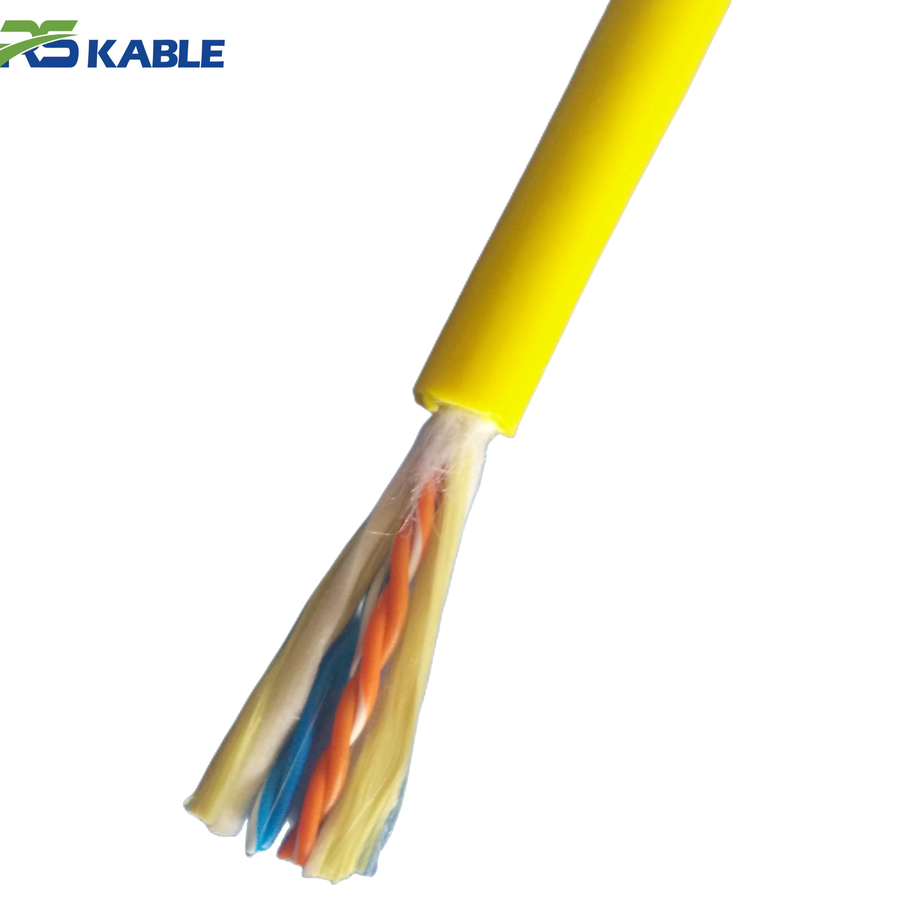
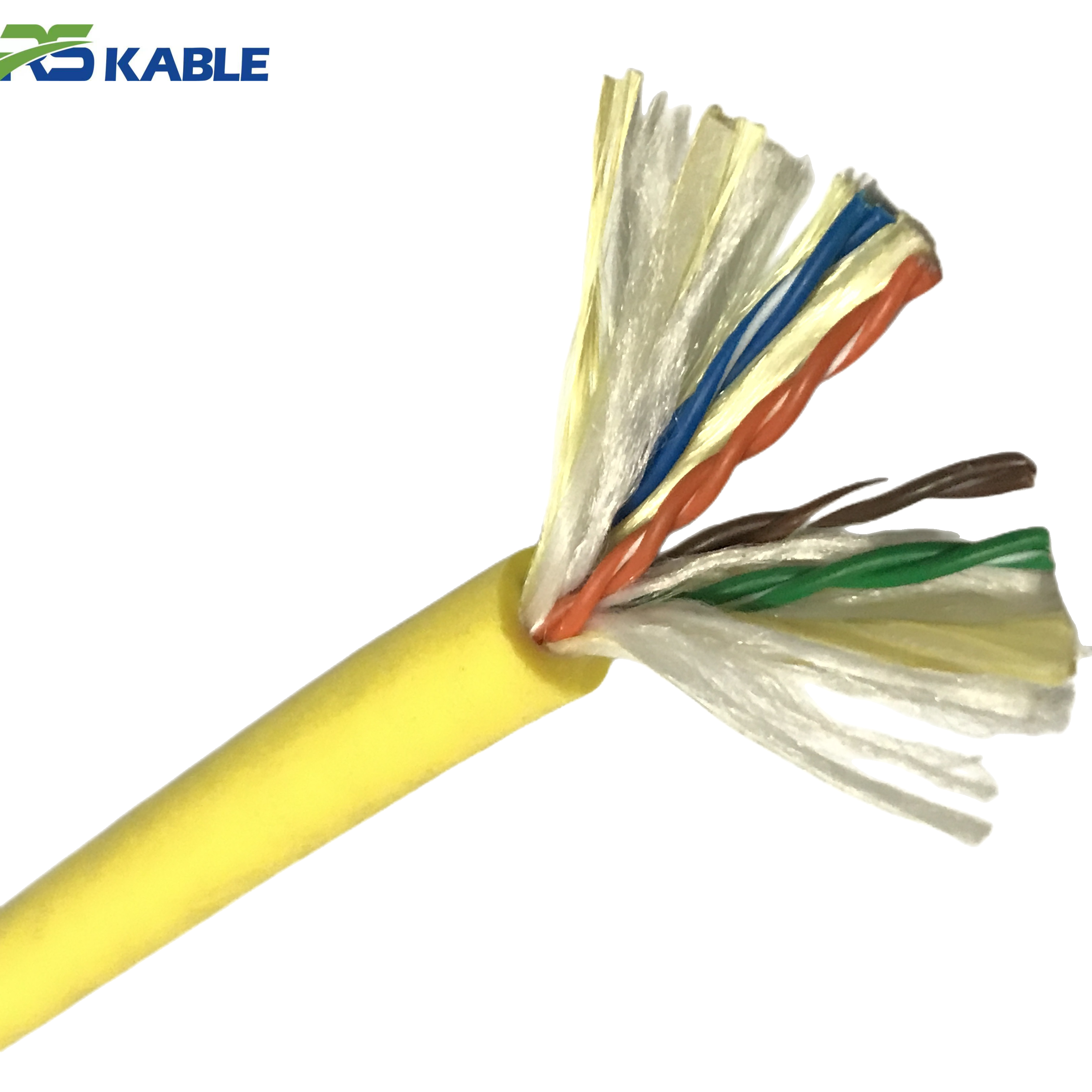
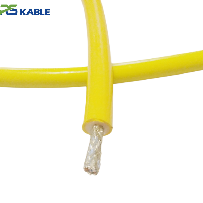
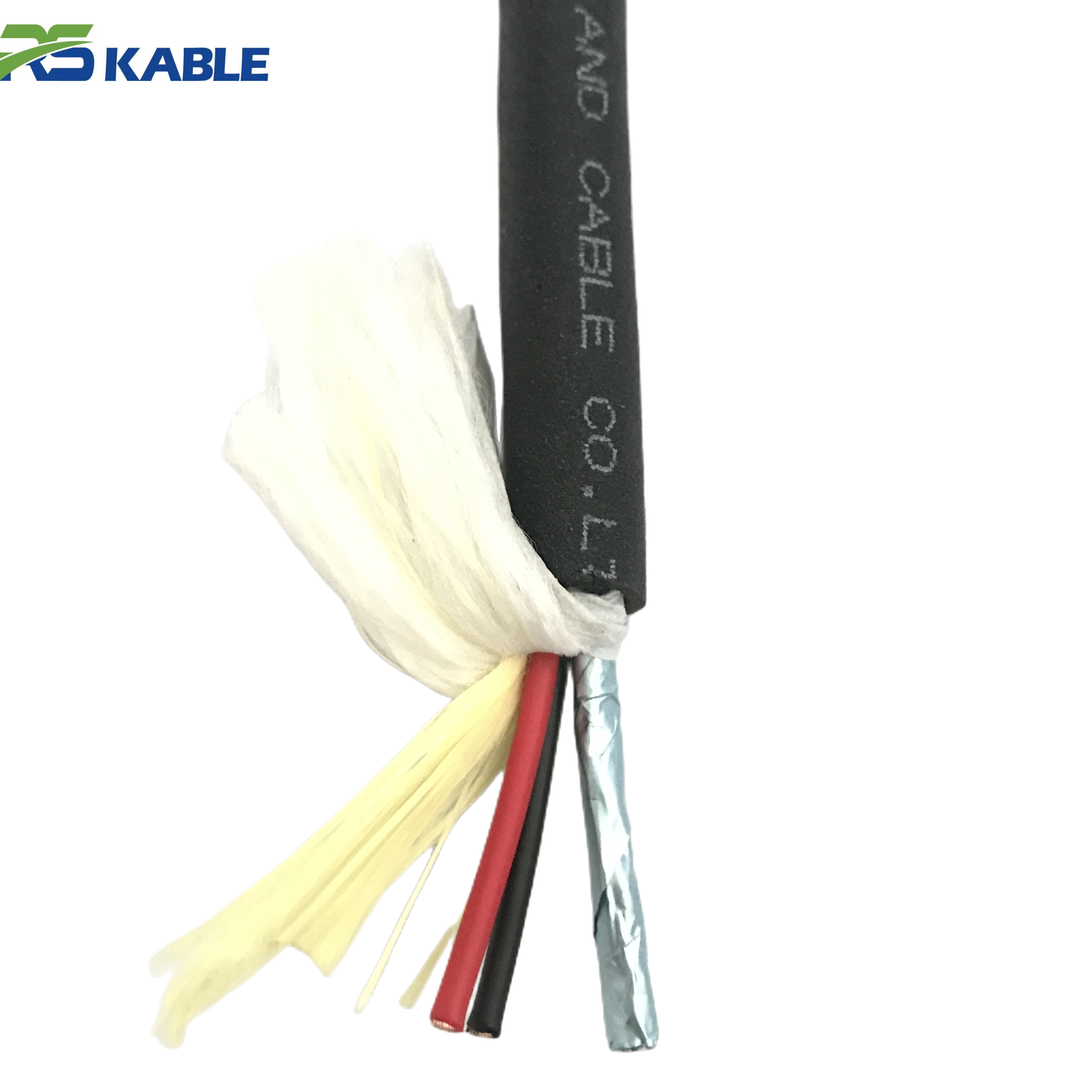
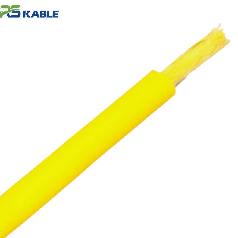
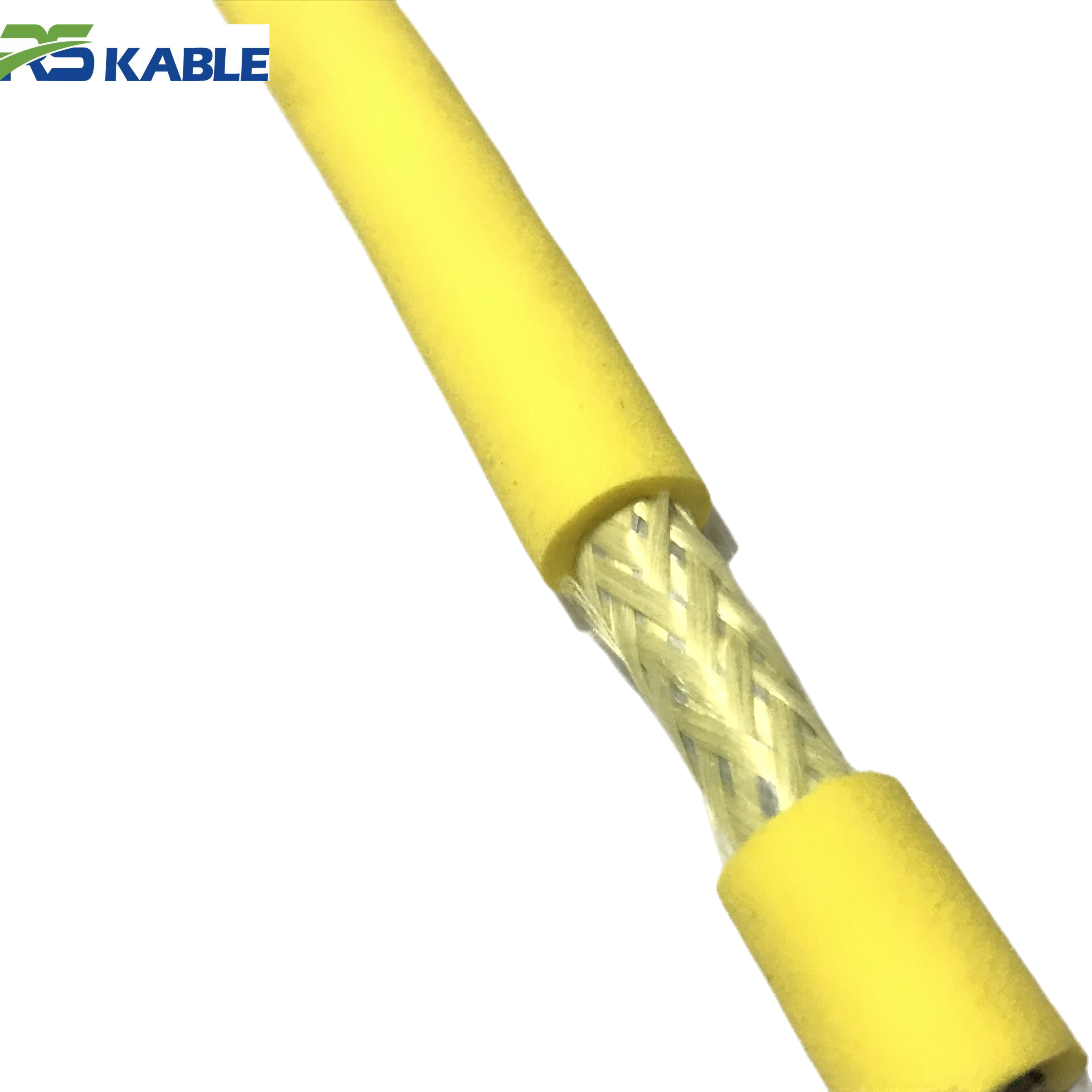
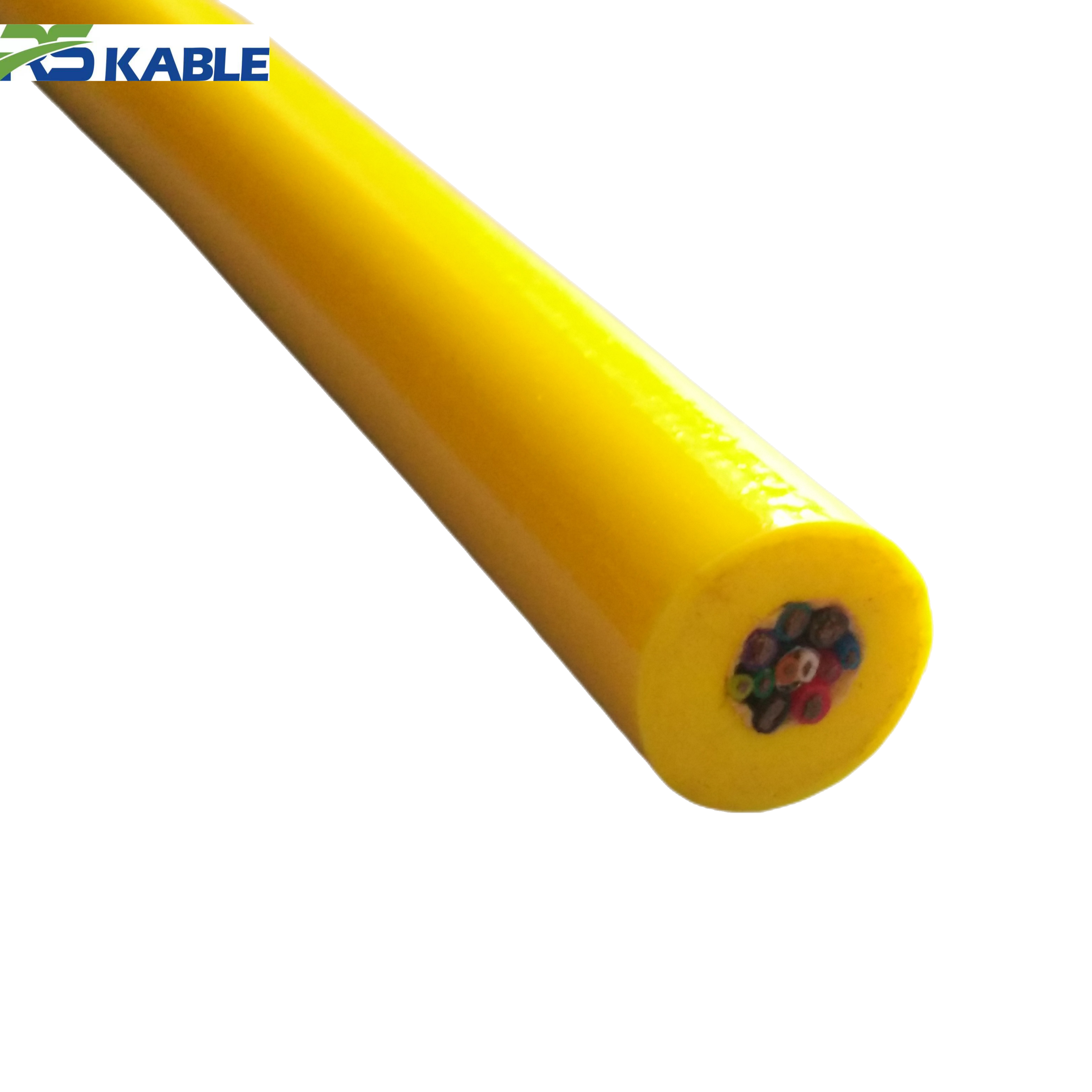
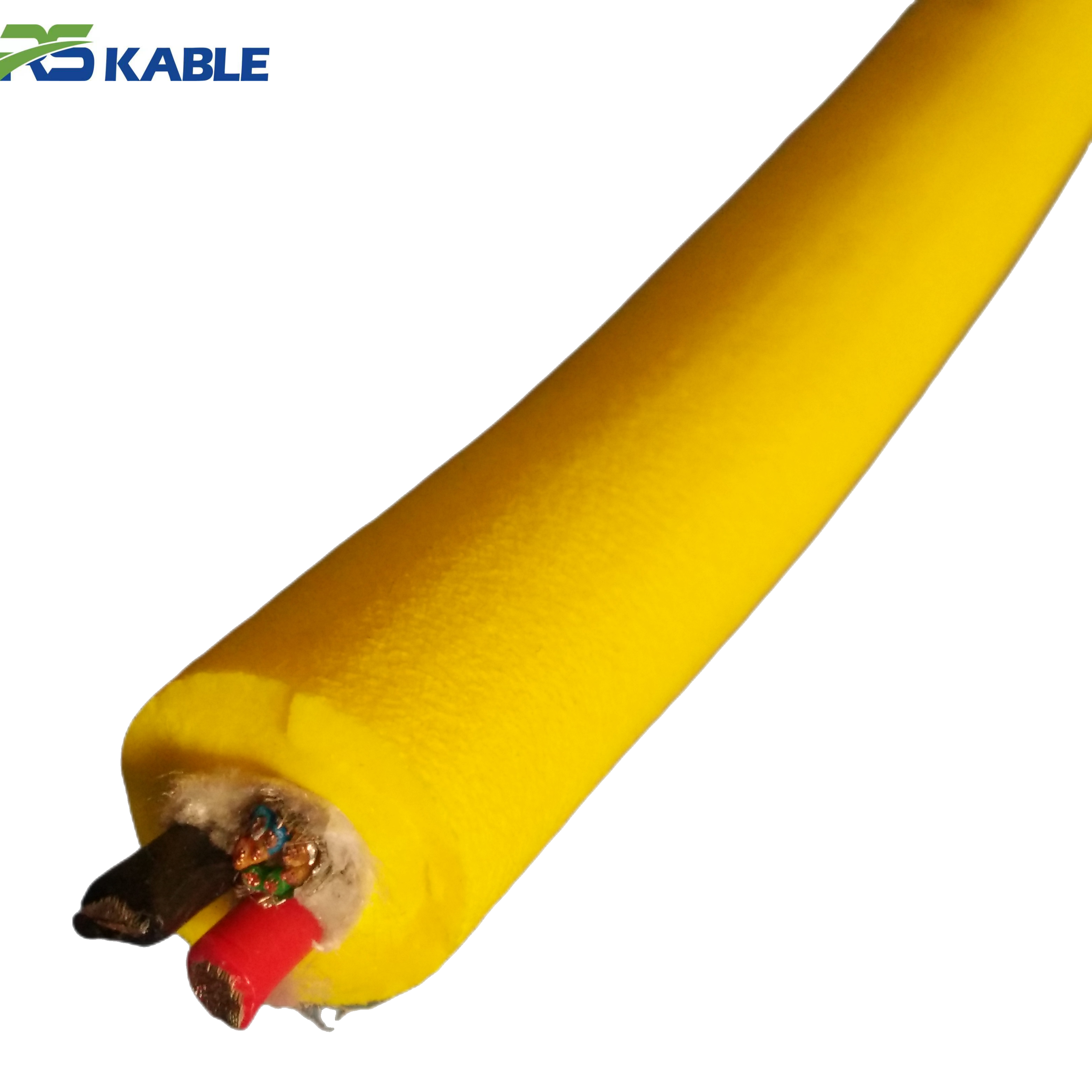
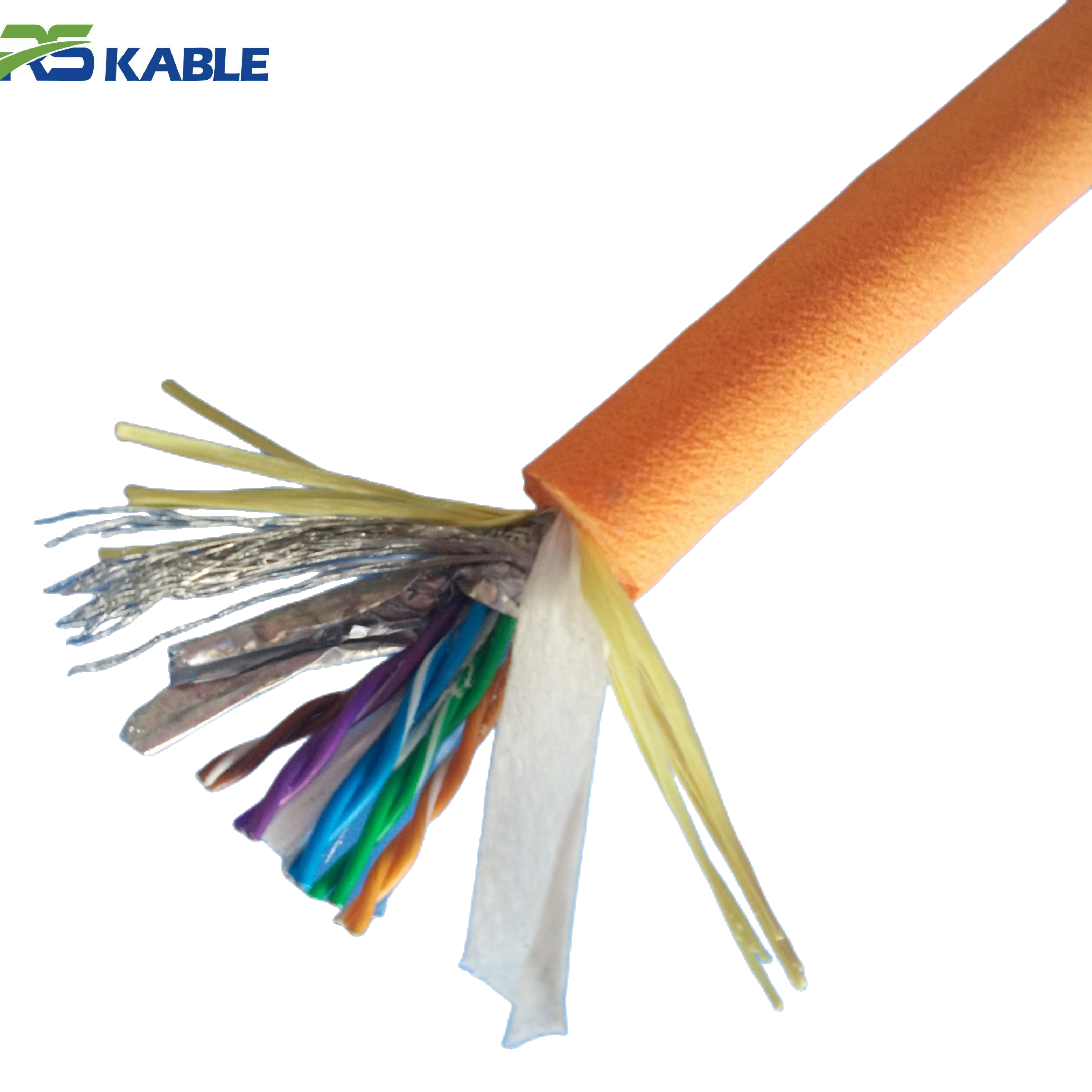
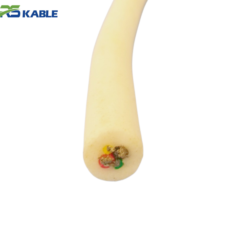
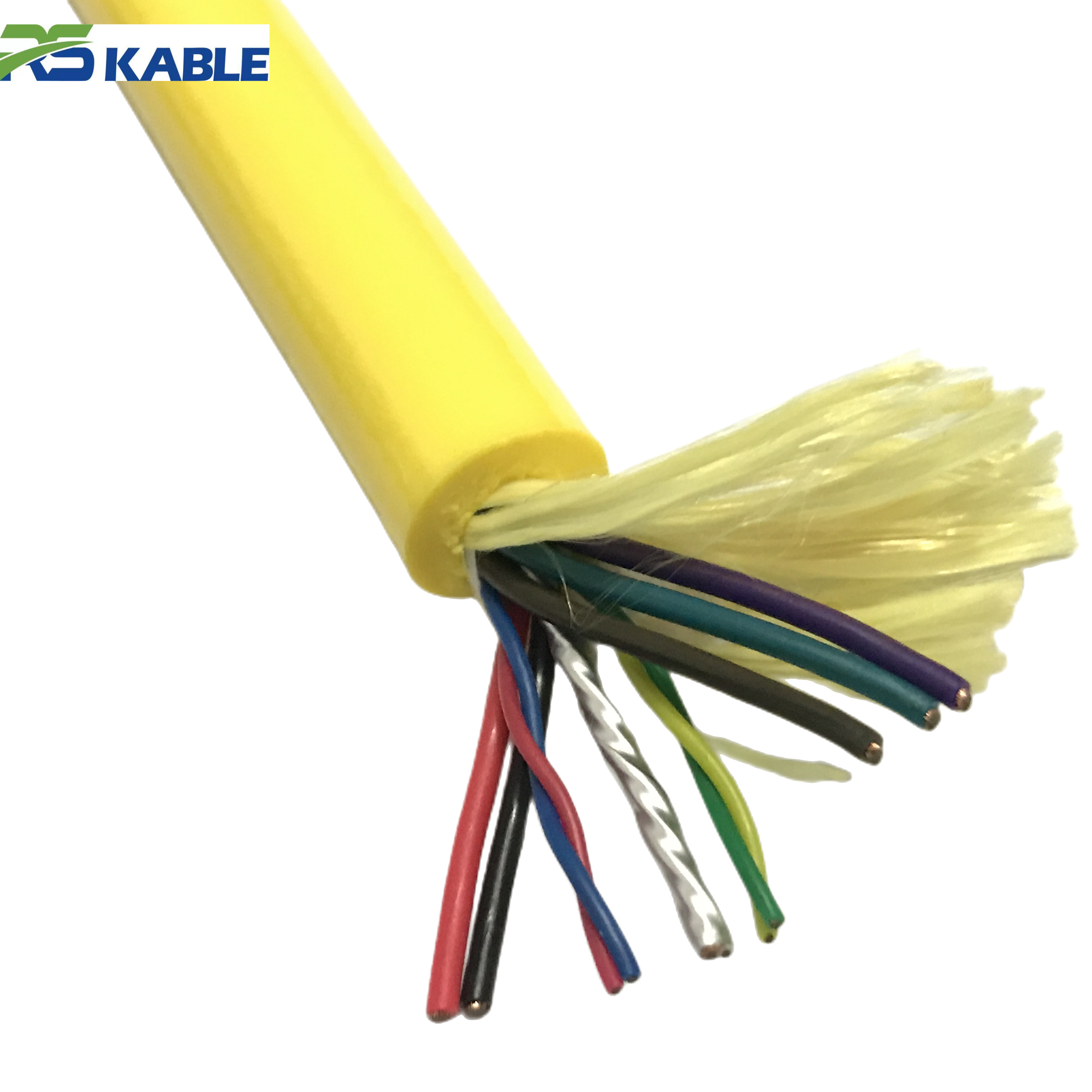
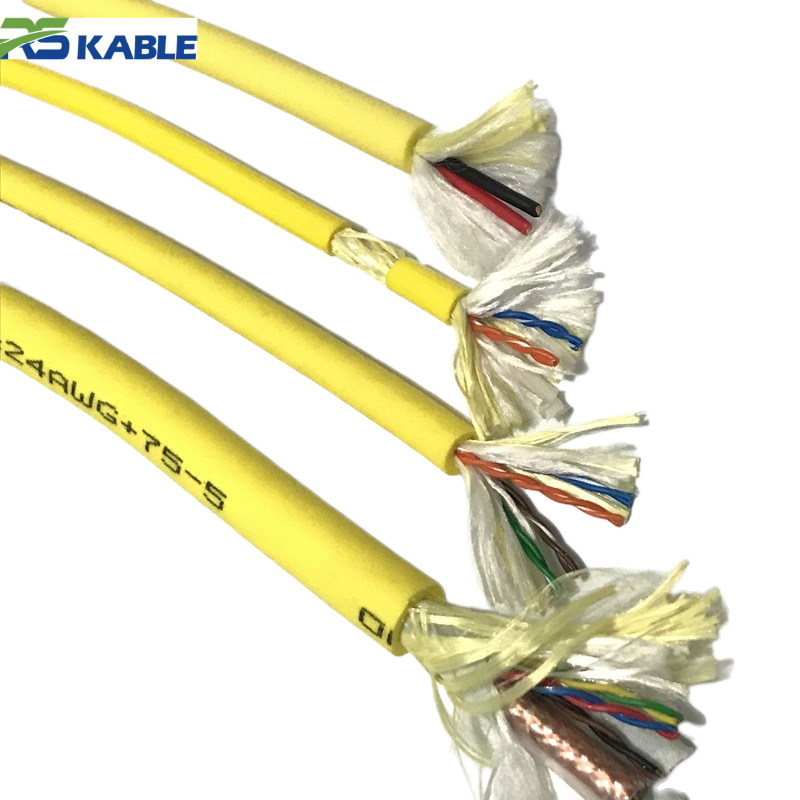
Custom High-Flex Hybrid Umbilical ROV Cable | Power, Coaxial, Signal & Fiber Optic Integration
This **custom-engineered umbilical cable** is the ultimate solution for complex **subsea ROV systems**, integrating **power, coaxial, signal, and fiber optic components** into a single high-flex structure. Designed for multi-functional underwater missions, it ensures seamless data telemetry and robust power delivery while maintaining superior durability in high-pressure deep-sea environments.
Load ratings: the terms you must pin down in every quote
Suppliers may use “tensile strength” to mean different numbers. Confirm which is being referenced:
-
MBL (Minimum Breaking Load): controlled failure point in a test
-
WLL (Working Load Limit): recommended safe working load below MBL
-
Strength member capacity: the reinforcement layer that should carry tensile load
-
Termination rated load: what the end system can tolerate (often lower than the cable body)
If the termination rated load is not stated, treat the quote as incomplete. A high MBL on the cable body is meaningless if the termination limits the system.
Where tension comes from in real operations
Instead of “maximum tension,” think in scenarios. Most operations see tension from these sources:
Operating tension (normal flight)
-
steady pull from the suspended length
-
current-driven side loads (especially in long catenary shapes)
-
transient spikes from maneuvering
Snag and friction tension
-
tether held by a contact point while the vehicle continues moving
-
“sticky” seabed contact during turns
-
friction at routing points that momentarily resists payout
Recovery tension (often the peak)
-
vessel motion + imperfect alignment
-
rapid retrieval under variable load
-
routing angle changes at fairleads/sheaves
-
slack snapping tight during recovery transitions
A safe tether specification must cover all three categories, not only normal flight.
Safety margin levels: a simple decision table you can actually use
Instead of arguing about one universal safety factor, select a margin level based on mission risk. Use this table to decide how conservative you should be.
Margin Level A — Standard
Best fit when:
-
open-water work
-
low snag environment
-
stable recovery method
-
limited vessel motion exposure
Must-have checks:
-
termination rated load documented
-
routing keeps bend radius within limits
-
crew procedure prevents slack snap-tight events
Margin Level B — Enhanced
Best fit when:
-
intermittent structure proximity
-
moderate currents and variable lead angles
-
recovery happens in realistic sea state (not ideal conditions)
Must-have checks:
-
termination rating confirmed to match system target
-
fairlead/sheave alignment reviewed
-
snag response procedure defined (stop/hold/reposition, not “pull through”)
Margin Level C — Conservative
Best fit when:
-
structure-dense inspection (pipelines, frames, debris fields)
-
frequent snag risk
-
long recoveries, higher vessel motion exposure
-
high-cycle operations with repeated bending
Must-have checks:
-
termination rated load is a hard requirement (not optional)
-
strain relief designed for repeated bending under tension
-
routing points and pinch risks mapped and mitigated
-
acceptance baseline recorded and reviewed after load events
This table keeps “safety margin” grounded in operational reality.
The real strength system: load path + termination + routing
A tether doesn’t fail because the cable body is weak. It fails because load concentrates in the wrong place.
1) Load path (what layer carries tension)
A proper design keeps tensile load in strength members—not in conductors or fibers. Ask suppliers:
-
which layer carries tension
-
how it is anchored
-
how it is protected from abrasion and moisture effects
2) Termination (where the load must be transferred)
The termination must:
-
anchor the strength members correctly
-
maintain sealing integrity
-
distribute bending away from the connector exit
-
avoid a sharp stiffness “hinge” point
3) Routing (where stress is repeatedly applied)
Repeated tight bends at the same routing point are fatigue accelerators. If the deck setup forces a tight radius, the tether will not deliver its rated life.
A mission-ready ROV Cable is a system, not a standalone product.
Overbuilding strength can reduce safety (why it happens)
Higher tensile capacity often increases:
-
OD and drag (more sweep zone in current)
-
stiffness (harder to route without violating bend limits)
-
contact frequency (more snag risk near structures)
-
fatigue concentration (stiffer transitions create sharper bend points)
That’s why selecting “the strongest available” can be counterproductive. The correct goal is: enough tensile margin for real spike events, while keeping handling controllable.
Practical “stop/monitor/continue” rules for tensile-related events
These rules help crews make consistent decisions after a load event.
Stop and inspect immediately if:
-
there was a known snag with a sharp tension increase
-
slack snapped tight during recovery
-
the tether experienced a hard fairlead angle change under load
-
the termination zone shows any new stiffness change or damage
Monitor closely if:
-
tension felt higher than normal but no clear event occurred
-
there is new scuffing near a routing point
-
the cable is laying unevenly on the drum (can indicate crushing or misrouting)
Continue only if:
-
post-event inspection shows no hard spots, no termination damage, and no routing violations
-
baseline checks remain stable (electrical/fiber if applicable)
Consistency prevents “one more dive” from becoming a failure.
Verification and acceptance: what to demand before deployment
Documentation requirements
-
cable body rating definition (MBL/WLL and test basis)
-
termination rated load with basis
-
strength member description and load path explanation
-
handling limitations: minimum bend radius and routing guidance
On-deck checks
-
no hard spots, kinks, crushed areas
-
termination strain relief is intact and transitions smoothly
-
routing confirms bend radius can be maintained under load
-
recovery procedure and safety zones are defined
If your deck setup cannot maintain bend radius and lead angles, do not assume the tether can “handle it.” Routing reality beats paperwork.
RFQ lines that prevent weak quotes (copy/paste)
-
Environment: open water / structure dense / debris risk (describe snag likelihood)
-
Maximum deployed length and typical operating profile
-
Recovery method and handling equipment details
-
Required margin level: Standard / Enhanced / Conservative (choose one)
-
Termination rated load must meet the system requirement
-
Bend radius requirement + routing constraints (fairleads/sheaves/drum)
-
Current profile if drag and sweep zone affect safety
-
Acceptance requirements: documentation + on-deck inspection steps
This forces proposals to include the full strength story, not just a single number.
FAQ
What’s the fastest way to avoid tensile-related failures?
Make termination rated load a hard requirement and design around recovery and snag spikes, not only steady operation.
Why does the termination fail when the cable body rating is high?
Because the termination is a separate system with its own load transfer and sealing limits. It’s commonly the weakest link.
How do I choose a safety margin without a universal number?
Use scenario-based levels (standard/enhanced/conservative) based on snag risk, recovery method, and sea state exposure.
Can overbuilt tensile strength increase snag risk?
Yes. Higher OD and stiffness increase drag and sweep zone in current, leading to more contact points and higher snag probability.
What should be verified before the first deployment?
Documentation of ratings (including termination), routing bend radius feasibility, strain relief integrity, and a defined recovery procedure.