ROV Cable Storage and Handling: Extend Tether Service Life
Poor ROV cable storage and handling practices are responsible for more tether failures than any subsea hazard. Crushing, kinking, UV exposure, and chemical contamination on deck cause damage that only shows up weeks or months later — often mid-dive.
This guide covers every stage of tether lifecycle management. It addresses drum configuration, deck handling, long-term storage, inspection schedules, and the repair decisions that separate recoverable damage from cable retirement.
The practices described here are drawn from offshore ROV operations across North Sea support vessels, Southeast Asian port inspection programs, and freshwater dam survey contracts.
What this article covers:
- The five failure modes that shorten tether life — and how to prevent each one
- Drum configuration and spooling practices that protect the cable structure
- Deck handling rules for offshore environments
- Long-term storage conditions and pre-deployment checklist
- Inspection intervals, retirement criteria, and repair decision logic
- Six FAQ answers to the most common questions from ROV operators
1. Five Failure Modes That Shorten Tether Life
Most tether damage is not sudden. It accumulates through repeated small insults. Understanding the five mechanisms helps you identify where your current practices create risk.
Overbending and kinking
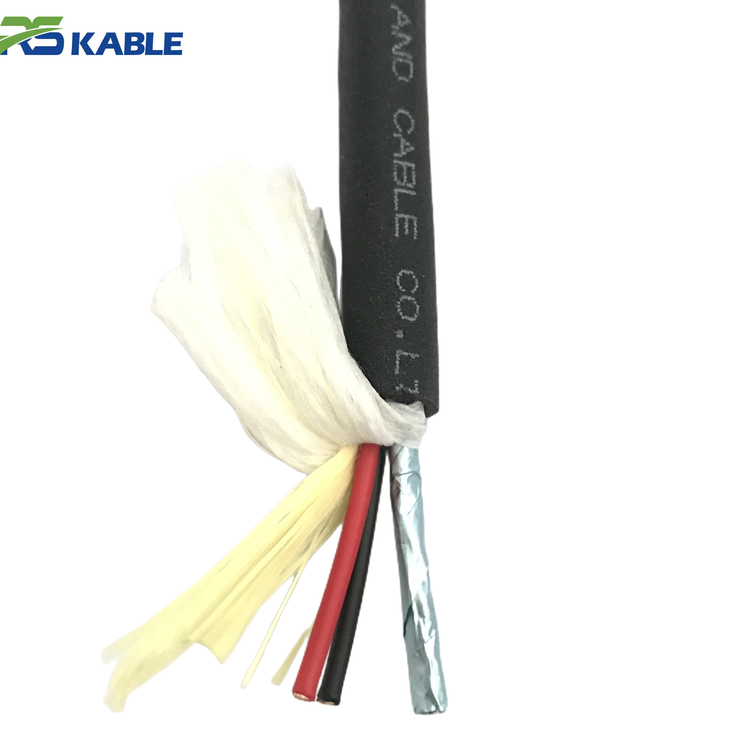
Every tether has a minimum bend radius. Exceeding it causes the outer armor wires to separate from the jacket, creating stress concentrations at the bend point. A single severe kink is often enough to break multiple armor wires internally — with no visible external sign until the jacket splits weeks later.
The minimum bend radius is published in the cable datasheet. It is typically expressed as a multiple of the outer diameter — for example, 10× OD for a dynamic tether. A 20 mm tether has a minimum bend radius of 200 mm. Bending it over a drum flange, a vessel rail, or a deck cleat at a tighter radius constitutes a damage event.
Crush loading
Tether crush damage occurs when the cable is trapped between hard surfaces under load. Common causes include: standing on the cable, driving wheeled equipment over it, clamping it under a deck fitting, and over-tensioning the spooling onto a drum with insufficient back tension control.
Crush damage deforms the jacket and can collapse the conductor insulation underneath. Unlike kink damage, crush damage tends to be distributed and may not produce a clear localized fault. Insulation resistance testing is the most reliable way to detect it.
UV and ozone degradation
Polyurethane and PVC jacket compounds degrade under prolonged UV exposure. The process is gradual — the jacket becomes brittle and surface-cracked after extended sun exposure. Ozone, present at elevated concentrations in marine air near electrical equipment, accelerates this degradation.
A tether stored on deck in direct sunlight in tropical latitudes can show visible jacket surface cracking within one season. This is not cosmetic — surface cracks propagate under dynamic bending, eventually reaching the armor layer.
Chemical contamination
Hydraulic fluid, lubricating oil, and fuel contaminate tether jackets on working vessels. Most jacket compounds are resistant to short-term hydrocarbon contact. Sustained immersion in hydraulic fluid — common when a tether is stored in a bilge area or near hydraulic equipment — causes jacket swelling and a measurable reduction in abrasion resistance.
Salt deposits left on the cable after seawater deployment accelerate jacket micro-cracking when the cable dries. Freshwater rinsing after every saltwater deployment is not optional maintenance — it is a basic preservation step.
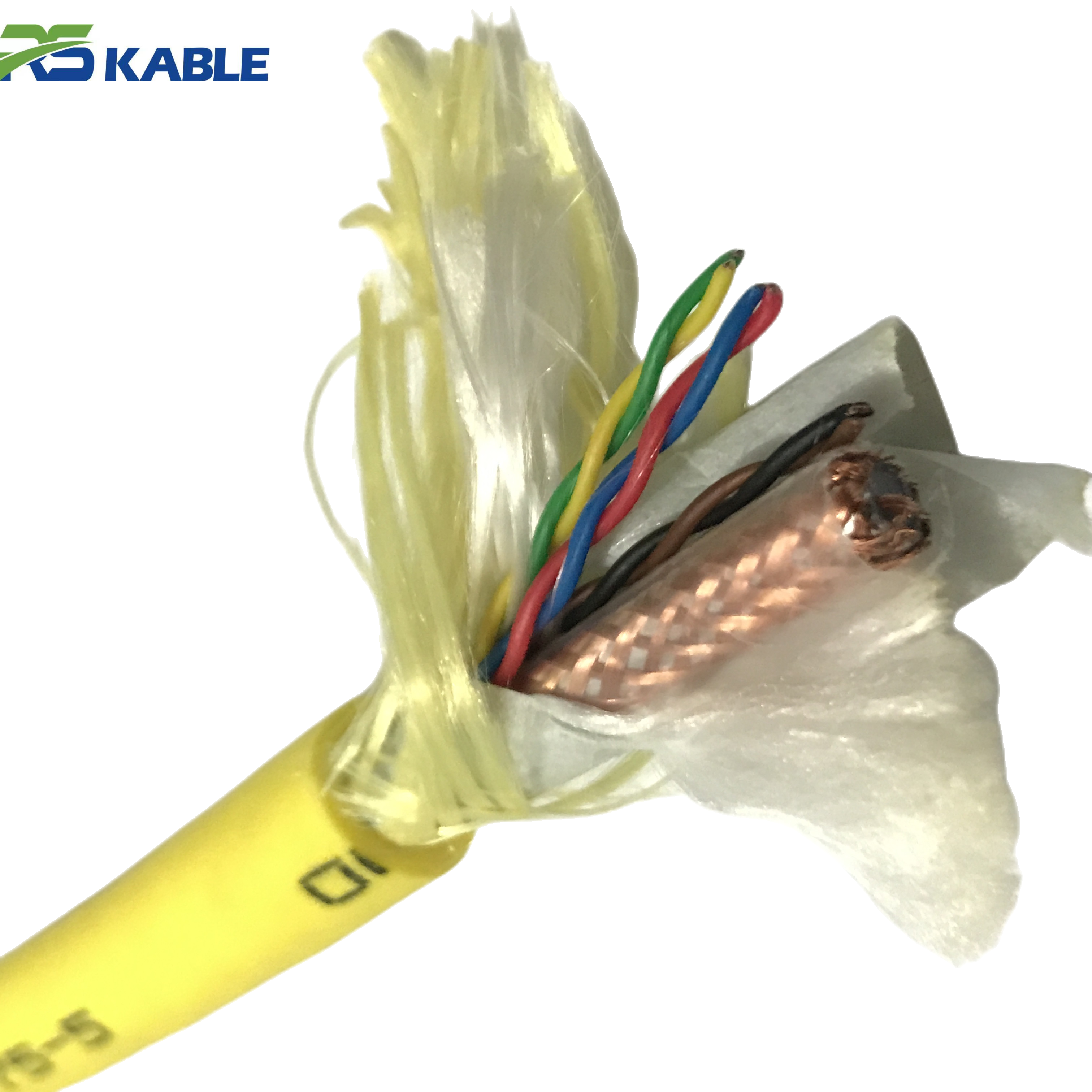
Connector contamination and corrosion
Wet-mate connectors on an exposed ROV tether are exposed to salt spray, cleaning chemicals, and mechanical contact. Pin corrosion, seal degradation, and backshell cracking are the three most common connector failure modes. They develop slowly and often produce intermittent faults that are difficult to diagnose without methodical isolation testing.
Connector failure is the single most common cause of tether-related system downtime in field operations we have reviewed. Yet it is almost entirely preventable with consistent protective cap installation and post-dive cleaning.
Field note: On a North Sea inspection vessel, a tether returned from a 14-day mobilization with visible connector pin corrosion on three of four signal pairs. The crew had not fitted protective caps on the topside connectors during transit. Repair required factory retermination — 6 days of vehicle downtime. The same tether with caps fitted and inspected at mobilization would have required no repair.
2. Drum Configuration and Spooling
Core drum diameter
The drum core diameter must be large enough that the innermost layer of tether does not exceed the cable’s minimum bend radius. For a 20 mm tether with a 10× OD minimum bend radius (200 mm), the drum core must have a minimum diameter of 400 mm — not 400 mm radius, but 400 mm diameter, which gives a 200 mm radius to the cable centerline at the innermost layer.
A drum core that is too small bends the innermost cable layers permanently with each use. The damage accumulates with each deployment and recovery cycle. After enough cycles, the innermost section of tether will fail even though the deployed section appears undamaged.
Spooling tension and layer control
Tether should be spooled onto the drum under controlled, moderate tension — typically 5–15% of the cable’s rated tensile strength for the first layer. Too little tension allows the lower layers to shift and cross. Too much tension crushes the cable on the drum under the weight of subsequent layers.
Each layer should be wound as tightly as possible against the previous layer. Gaps between turns allow adjacent turns to migrate and overlap under tension during deployment. Overlapping turns create crush points that damage the cable at the crossing location.
Flange clearance
The drum flange must extend above the outermost cable layer by at least one full cable diameter. This prevents the tether from riding over the flange under tension — a failure mode that can snap the cable at the flange edge under dynamic vessel motion.
Check flange height before the first deployment with any new tether. If the tether diameter is larger than the drum was designed for, the drum is unsuitable. Do not improvise with shims or padding on the flange.
Level wind systems
A level wind guide distributes tether evenly across the drum width during recovery. Without it, the cable piles up in the center and creates an unstable spool that can collapse sideways under load. Level wind systems are standard on professional ROV deployment drums but are often absent on smaller observation-class systems.
If your system lacks a level wind guide, assign a crew member to manually guide the cable during recovery using a clean, non-sharp guide. Gloves are mandatory. Bare hands on a recovering tether under tension will cause injury.
Drum specification checklist: Core diameter ≥ 2× minimum bend radius of cable · Flange height ≥ 1× cable OD above top layer · Drum width matches planned spooling length with 10% margin · Level wind guide fitted or manual guidance protocol in place · Drum bearing capacity rated for full tether weight plus dynamic load factor
3. Deck Handling on Offshore Vessels
Deployment and recovery protocols
The highest-risk moments for tether damage are during deployment and recovery. The cable transitions from a controlled spool to a dynamic load path over the vessel stern or A-frame. Several rules reduce risk at these transition points.
The fairlead or sheave that guides the tether over the vessel stern must have a groove radius no smaller than the tether’s minimum bend radius. A sheave that is too small is a damage event on every deployment cycle. Check the sheave specification against the tether datasheet before the first deployment.
Recovery speed should be reduced in the last 20–30 m of tether. At short scope, the angle between the tether and the vessel stern changes rapidly as the vehicle approaches. This creates dynamic bending loads that can exceed the tether’s fatigue limit if recovery speed is not controlled.
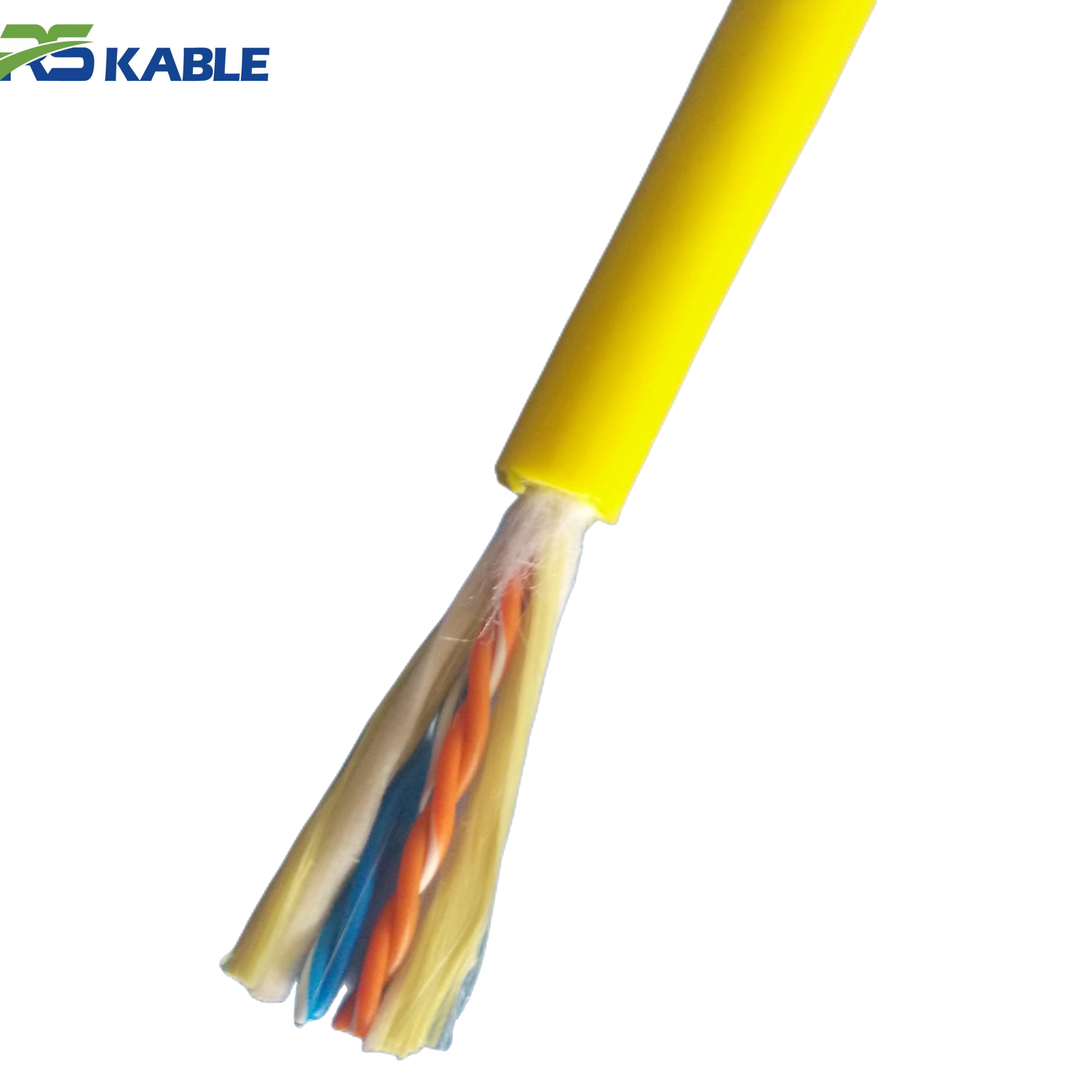
Twist management
ROV tethers accumulate twist during operation, particularly when the vehicle rotates under current or during manipulator operations. Unmanaged twist reduces effective tensile strength and causes the tether to coil on the deck during recovery.
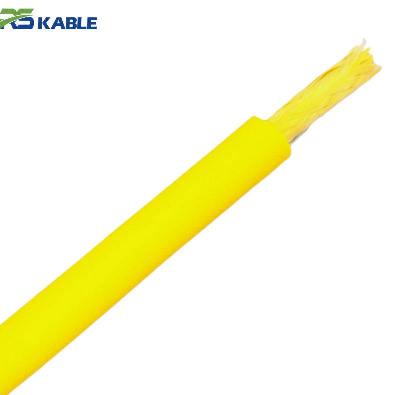
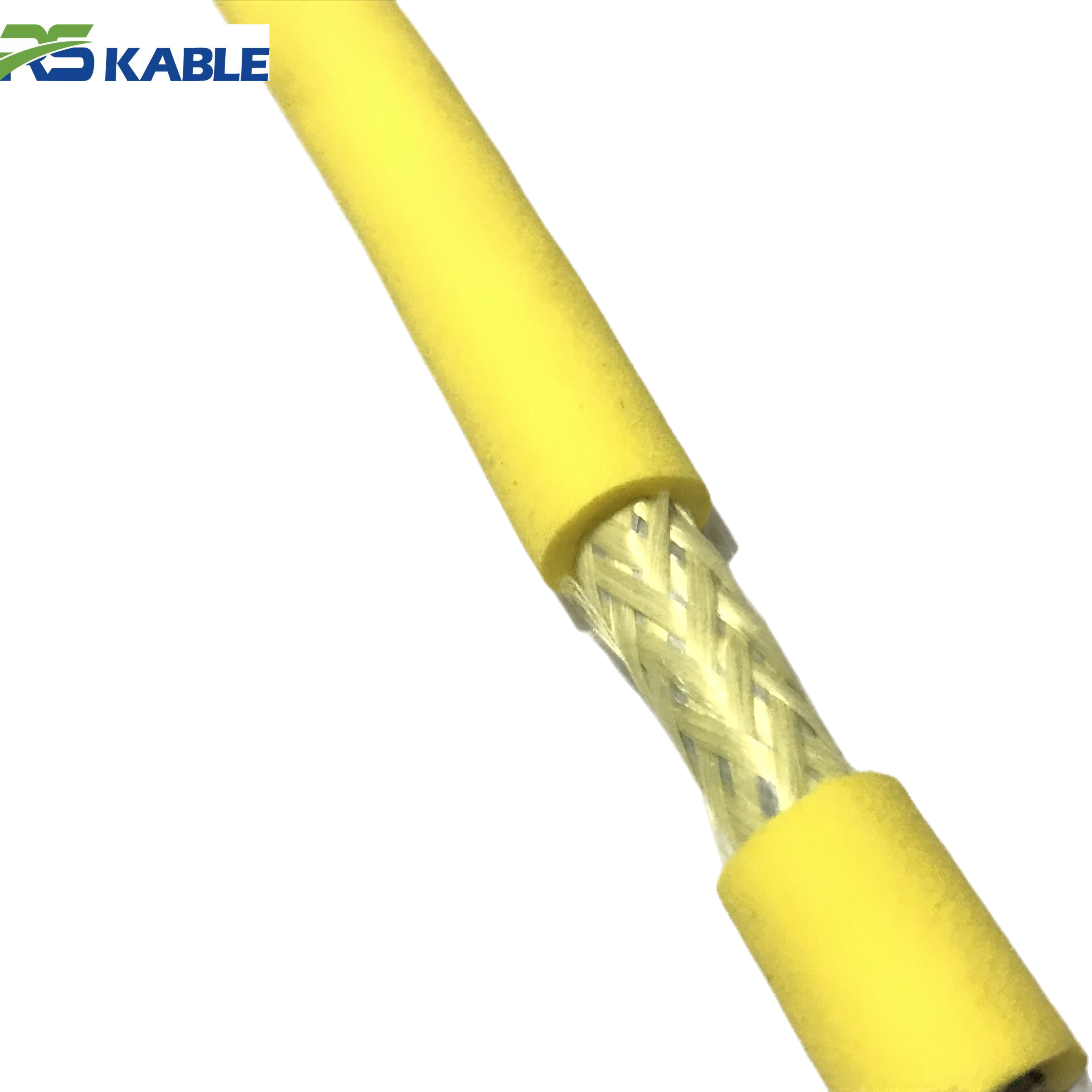
Torsionally balanced tethers — with counter-helical armor layers — manage twist better than single-armor designs. Even so, twist should be manually removed from the deployed section of tether after each dive by allowing the free end to rotate before spooling. Never spool a twisted tether under tension.
Contact with deck structures
A tether in contact with a sharp deck edge, a bolt head, or a corroded fitting during deployment or recovery will abrade through its jacket within a few dives. Identify all potential contact points before the first deployment and fit polyurethane or rubber chafe protection at each one.
Pay particular attention to the vessel stern rail, the A-frame pad-eye connections, and any deck penetration through which the tether passes. These are fixed contact points that will cause damage every time if not protected.
Foot traffic and equipment
Establish a clear exclusion zone for vehicle traffic around any deployed or staged tether. A single pass by a forklift or wheeled equipment trolley over a 20 mm tether can create a crush point that passes visual inspection but fails under dynamic load.
Mark the cable path with high-visibility tape when the tether is laid across a working deck. Brief all deck crew at the start of each mobilization. The briefing takes two minutes and prevents damage that costs days to repair.
4. Long-Term Storage Conditions
Temperature and humidity
Tether should be stored in a clean, dry environment with ambient temperature between 5°C and 35°C. Temperatures below freezing cause polyurethane jacket compounds to become brittle. A tether stored at −10°C and then deployed without a warm-up period is at high risk of jacket cracking during the first handling cycle.
High humidity accelerates corrosion on exposed armor wire ends and connector pins. If the storage environment cannot be controlled for humidity, apply a light film of corrosion inhibitor to exposed metallic surfaces and fit protective caps on all connectors.
UV protection
Tether stored outdoors — even on a covered deck — must be protected from direct UV exposure. A UV-opaque tarpaulin or a drum cover is adequate. The tarpaulin must completely cover the drum without gaps, as concentrated UV through a small gap can cause localized jacket degradation faster than general exposure.
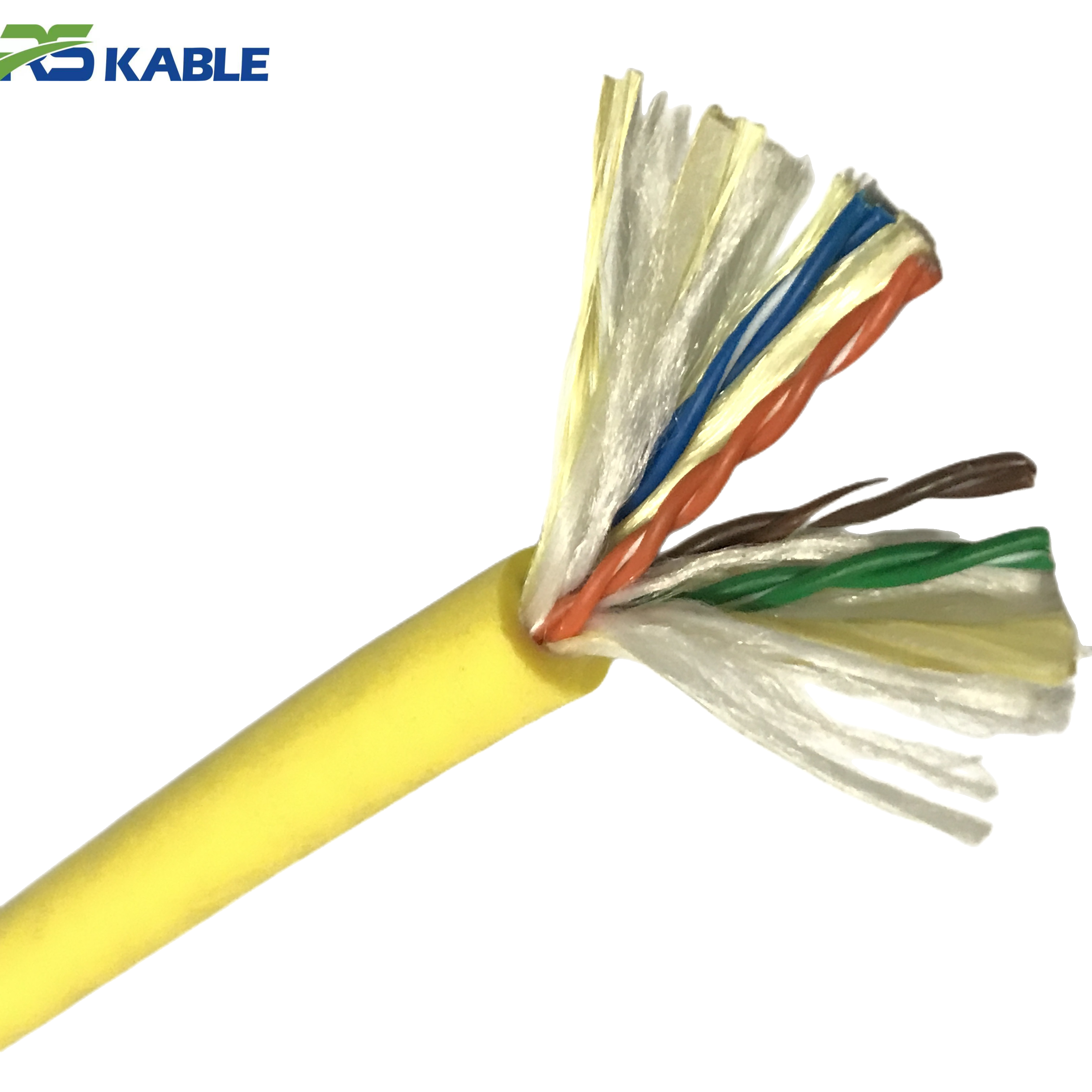
Spooling for storage
For storage periods longer than 30 days, spool the tether onto the drum with the same care used for operational deployment. Do not leave the tether in loose coils on the deck or in a storage bin. Loose coils allow the cable to take a set — a permanent curve that causes lay-up problems on the drum and increases fatigue loading at the set points during operation.
If the tether must be removed from the drum for storage, coil it in figure-eight loops rather than circular coils. Figure-eight coiling cancels the twist that accumulates in circular coiling and allows the tether to be re-spooled without the twist management step.
Connector storage
All connectors must have protective caps fitted before storage. This applies to both the tether end connectors and any spare mating halves. Caps should be inspected for seal integrity before fitting — a damaged cap provides less protection than no cap, because it creates a closed humid environment against the connector face.
Silica gel desiccant packets inside the cap housing are a practical addition for connectors stored in high-humidity environments. Replace the desiccant at each pre-deployment inspection.
Storage specification summary: Temperature: 5–35°C · Humidity: <70% RH preferred · UV: full cover required · Spooling: proper tension, not loose coils · Connectors: caps fitted, desiccant if humid · Inspection: full check before any deployment after >30 days storage
5. Inspection Intervals and Retirement Criteria
Post-dive inspection
Run the tether through a clean cloth during recovery. The cloth will catch protruding armor wires, jacket damage, and contamination that visual inspection from a distance misses. Log any findings with the location along the tether length.
After every dive in an abrasive environment — rocky seabed, inside a jacket structure, or over coral — visually inspect the full deployed length under good lighting. Pay particular attention to the first and last 10 m of tether, which experience the most dynamic bending load.
Periodic electrical testing
Conduct a full electrical test at the following intervals:
- After each mobilization to a new site
- Every 30 operating days during a continuous campaign
- After any incident involving tether contact with a hard surface
- Before deployment after any storage period longer than 60 days
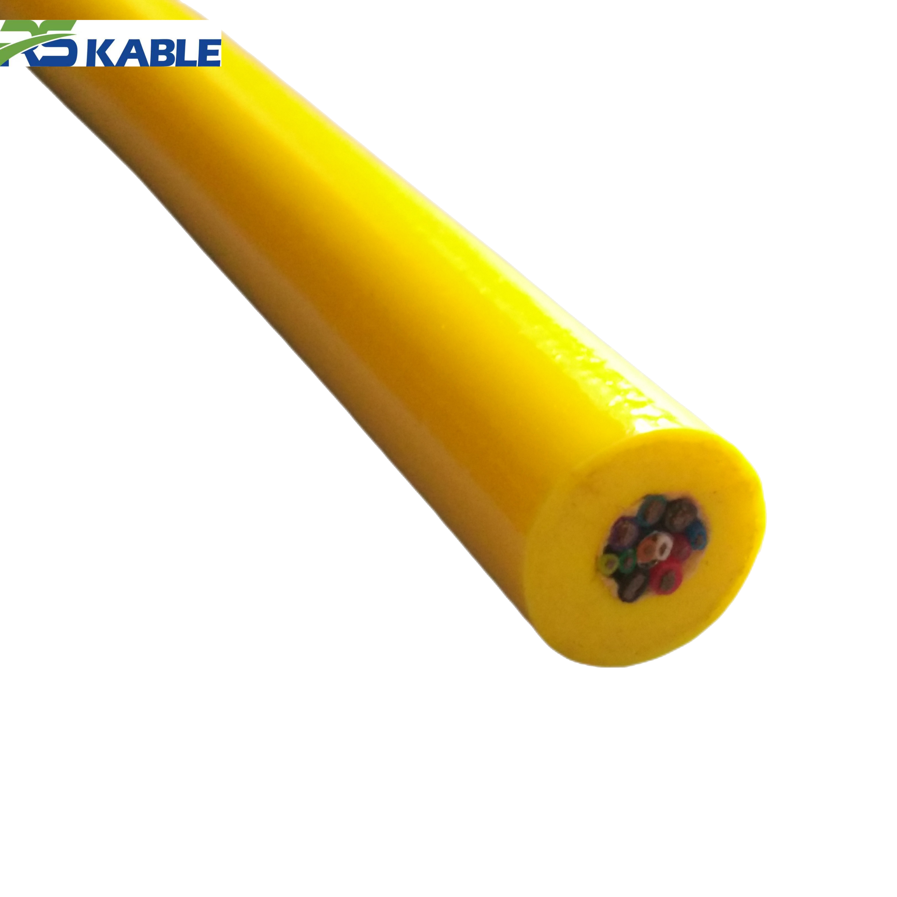
The minimum electrical test set includes: insulation resistance (IR) test on all conductor pairs at 500 VDC, conductor continuity resistance measurement (4-wire method), and shield continuity check. Log all results with date and tether operating hours.
Retirement criteria
Retire the tether immediately if any of the following conditions are present:
- Insulation resistance below the manufacturer’s published minimum floor value (typically 100 MΩ at 500 VDC)
- Two or more adjacent broken outer armor wires in any 300 mm section
- Jacket penetration that exposes underlying armor or insulation
- Conductor resistance more than 15% above the datasheet value for the current temperature
- Any connector that cannot be brought to specification by cleaning and re-greasing
Single broken armor wires in isolated locations, with jacket intact, may be accepted for continued operation with increased inspection frequency and a recorded deviation — subject to the tether manufacturer’s written guidance.
Repair vs replace decision
Factory retermination — replacing the damaged connector end — is economical when the cable body is undamaged and the connector damage is at the termination point. Field repairs to the cable body itself are generally not recommended for dynamic offshore tethers. A field-repaired section has lower fatigue resistance than the original cable construction. It should be treated as a short-term measure pending replacement, not as a permanent fix.
|
Damage type |
Repair viable? |
Action |
Urgency |
|
Connector pin corrosion (mild) |
Yes |
Clean, re-grease, retest |
Pre-next dive |
|
Connector retermination required |
Yes — factory |
Return to manufacturer |
Off-hire |
|
Jacket surface scoring (no exposure) |
Monitor |
Log, increase inspection |
Next 30 days |
|
Jacket penetration to armor |
No |
Retire section or full cable |
Immediate |
|
Multiple adjacent armor wire breaks |
No |
Retire — do not deploy |
Immediate |
|
IR below minimum floor value |
No |
Remove from service |
Immediate |
|
UV surface crazing (no cracking) |
Monitor |
Increase cover, log |
This mobilization |
Table 1. Repair vs retire decision matrix. “Retire” means remove from dynamic offshore service — a retired tether may be suitable for static or low-risk applications at the operator’s discretion.
6. Pre-Deployment Checklist
Run this checklist before every first dive of a new mobilization and after any period of inactivity longer than two weeks.
Visual inspection
- Full tether run-through: Pass full tether through a clean cloth during controlled recovery or manual deployment. Flag any resistance or protrusion.
- Connector inspection: Remove caps. Inspect all pins for corrosion, bent contacts, or contamination. Check sealing face for damage. Clean with appropriate solvent.
- Jacket inspection: Inspect the first and last 10 m of tether at a minimum. Check for surface cracking, scoring, swelling, or chemical staining.
- Drum condition: Check for smooth, even layers on drum. No crossed turns, no gaps, no protruding loops at the flange.
Electrical testing
- Insulation resistance: All conductor pairs to shield, 500 VDC, minimum 100 MΩ. Record result and date.
- Conductor resistance: 4-wire measurement of each conductor loop. Compare to last recorded baseline. Flag any increase > 5%.
- Shield continuity: Confirm all shields are continuous end-to-end. Resistance should be stable and match expected value.
- Communications check: Connect vehicle and confirm all signal channels and fiber links functional before deployment.
Environmental preparation
- Fairlead and sheave check: Confirm groove radius is appropriate for the tether diameter. Apply light grease if specified by manufacturer.
- Chafe protection: Confirm all deck contact points are fitted with appropriate chafe guards. Check guards are secure.
- UV cover: Remove UV cover only immediately before deployment. Do not leave the drum uncovered during extended deck standby.
7. The Return on Good Practices
What the numbers show
Well-managed ROV cable storage and handling routines consistently extend tether service life by 40–60% compared to baseline operations without a formal maintenance protocol. That estimate is based on failure logs from three ROV operators who implemented structured inspection and handling procedures and tracked tether replacement intervals before and after.
The direct cost saving is straightforward. A quality work-class tether costs USD 8,000–25,000 depending on length and specification. Extending its operating life from 18 months to 28 months on the same workload saves the replacement cost minus the protocol overhead — typically 3:1 or better return on the time invested in training and procedure implementation.
The indirect cost is larger
Unplanned tether failure offshore creates downtime costs that dwarf the tether replacement cost. A day of lost survey time on a chartered offshore support vessel can cost USD 20,000–80,000 in vessel day rate alone, not counting client penalties, crew overtime, and mobilization costs for a replacement cable.
Every tether failure that was preventable by better deck handling or storage practice is not just a cable cost — it is a mobilization cost, a schedule cost, and a client relationship cost. The ROV cable storage practices described in this article are the least expensive insurance policy available against all three.
Specifying a replacement tether or reviewing your current maintenance protocol? Our applications team provides technical support for tether selection, drum sizing, and maintenance procedure development. Share your current tether specification and operating profile — we will return a written assessment with recommendations.
Frequently Asked Questions
Q1: How often should ROV cable storage conditions be checked during a long campaign?
For any campaign longer than 30 days, inspect the tether storage condition at the start of each new week. Check the drum cover for damage and gaps. Confirm connectors still have caps fitted. Look for any new contamination — oil drips, fuel spills, or cleaning chemical residue near the drum. Log the inspection date and findings. If the vessel is in port for more than 48 hours, take the opportunity to run a quick electrical test as well. Short storage inspections take under 10 minutes. The effort is trivial compared to the downtime risk of missing developing damage.
Q2: Can a kinked ROV tether be repaired and returned to service?
A kink in a dynamic offshore tether is a retirement event in most cases. Kinking permanently separates the armor wire lay and creates a stress concentration that will fail under fatigue loading — usually without visible external warning. The only exception is a kink that occurred in a very short section of tether that can be cut out and the cable reterminated. This is only viable if the kink is within the last 0.5–1 m of the tether, close to the connector end. If the kink is mid-tether, the cable must be retired. A kinked tether that appears undamaged externally is not safe to deploy.
Q3: What is the correct way to clean an ROV tether after a saltwater deployment?
Rinse the full deployed length with fresh water immediately after recovery. Use a low-pressure hose — high-pressure washing can force water into micro-cracks in the jacket and accelerate damage. Pay particular attention to the connector interfaces and the armor wire end terminations. After rinsing, allow the tether to drain and air-dry before spooling or covering. Do not spool a wet tether onto a closed drum if storage will exceed 24 hours — trapped moisture promotes corrosion on the armor wires and connector pins. If possible, leave the drum cover partially open for ventilation during the first 4 hours of drying.
Q4: How does temperature affect ROV cable storage life?
Temperature is the most significant environmental factor in long-term storage degradation. Polyurethane jacket compounds lose flexibility below 0°C and become prone to cracking during handling. Above 50°C — achievable inside an unventilated container on a vessel in tropical sun — the jacket softens and can take a permanent set or deform under the weight of drum layers. The ideal storage temperature range is 10–30°C. If storage outside this range is unavoidable, allow the tether to equilibrate to ambient handling temperature for at least 2 hours before any bending or spooling operation.
Q5: Should the tether be lubricated, and with what product?
The cable body itself does not require lubrication. Lubricants applied to the outer jacket can degrade the jacket compound over time, depending on the product chemistry. The exception is the sheave groove and fairlead contact point — light grease applied to the sheave groove reduces abrasion at the contact interface. Use a grease compatible with polyurethane. Check the tether manufacturer’s recommendation before applying any product to the jacket directly. Connector pin contacts should be treated with the connector manufacturer’s specified dielectric grease — not a general-purpose lubricant. Use of the wrong product can compromise the connector’s sealing and corrosion performance.
Q6: What are the signs that a tether needs replacement before it fails in service?
Several early warning signs are detectable before catastrophic failure. First, a gradual trend of rising conductor resistance over multiple test cycles — without any change in tether length or temperature — indicates progressive conductor degradation. Second, insulation resistance readings that are declining across successive measurements suggest developing jacket or insulation damage. Third, visible surface crazing across a significant proportion of the jacket length, rather than isolated scuff marks, indicates advanced UV or chemical degradation. Fourth, connector pins that require increasing cleaning effort to pass continuity tests. Any one of these trends should trigger a replacement planning decision — do not wait for complete failure during a dive.