Common ROV Cable Failure Modes in Offshore Operations and Preventive Solutions
In offshore subsea work, a cable rarely fails without warning. The real problem is that the warning signs are often missed, misunderstood, or treated as routine wear. For ROV teams working on inspection, intervention, subsea construction, and deepwater maintenance, the tether is far more than a connection between vehicle and surface. It carries power, video, telemetry, sensor feedback, and control signals that the entire operation depends on. When one ROV Cable begins to degrade, the impact can spread quickly across the mission: unstable video, intermittent thruster response, loss of tooling power, signal noise, emergency recovery, and expensive vessel downtime.
That is why failure analysis matters. Offshore teams do not just need to know that abrasion, fatigue, water ingress, or connector damage can happen. They need to know where these failures usually start, how they develop, what the first visible clues look like, and what preventive steps actually work in real operations. This article is written from that practical perspective. It explains the most common offshore tether failure modes, the root causes behind them, the typical early warning signs, and the preventive solutions that reduce repeat failures in the field.
If your audience includes offshore contractors, ROV operators, subsea engineers, marine maintenance teams, or procurement staff sourcing subsea umbilicals, this topic also works well for blog traffic because it matches real search behavior. People do not only search for “cable specs.” They also search for things like offshore ROV tether failure, water ingress in subsea cable, umbilical abrasion damage, and how to inspect marine robot cable after deployment.
Why Offshore Tethers Fail More Often Than Teams Expect
An offshore tether operates under a combination of stresses that very few industrial products experience at the same time. During one campaign, the same line may be bent over sheaves, compressed on a reel, twisted by vessel motion, dragged across deck hardware, exposed to seawater and hydrocarbons, and then deployed again under tension. Meanwhile, it is still expected to maintain stable electrical and communication performance.
That is why most offshore cable failures are not caused by a single catastrophic event. They usually develop through repeated smaller problems, such as:
-
bending tighter than the recommended bend radius
-
repeated abrasion at one guide point
-
poor spooling tension
-
terminations that flex too close to the connector body
-
water entering through minor jacket damage
-
crush loading during mobilization or deck operations
-
signal degradation caused by internal damage or moisture
In practice, the tether often starts failing long before the team calls it a failure. The key to better reliability is learning to identify the first stage of damage rather than waiting for a full fault.
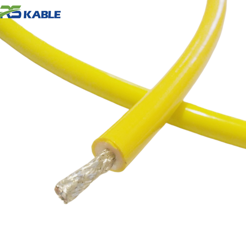
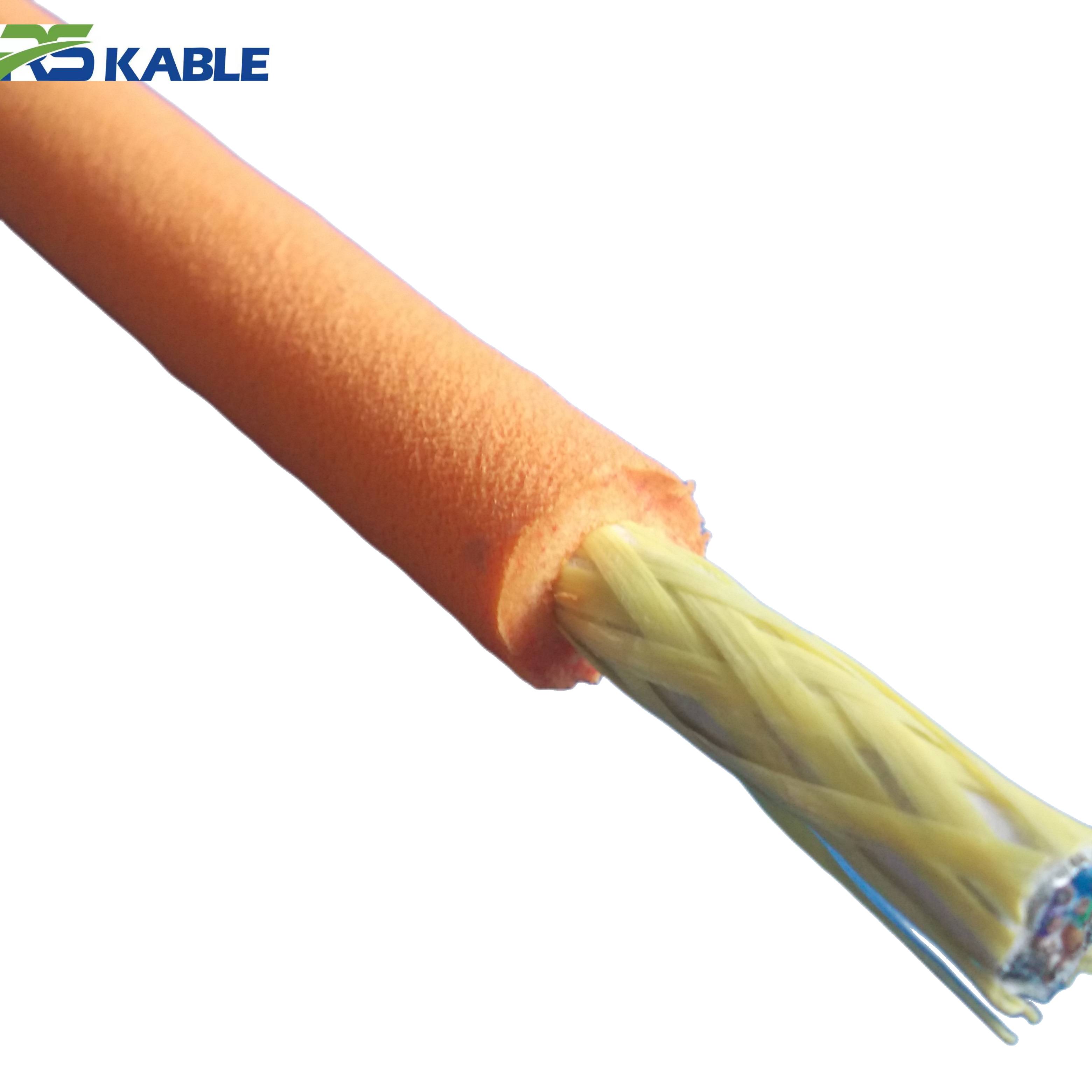
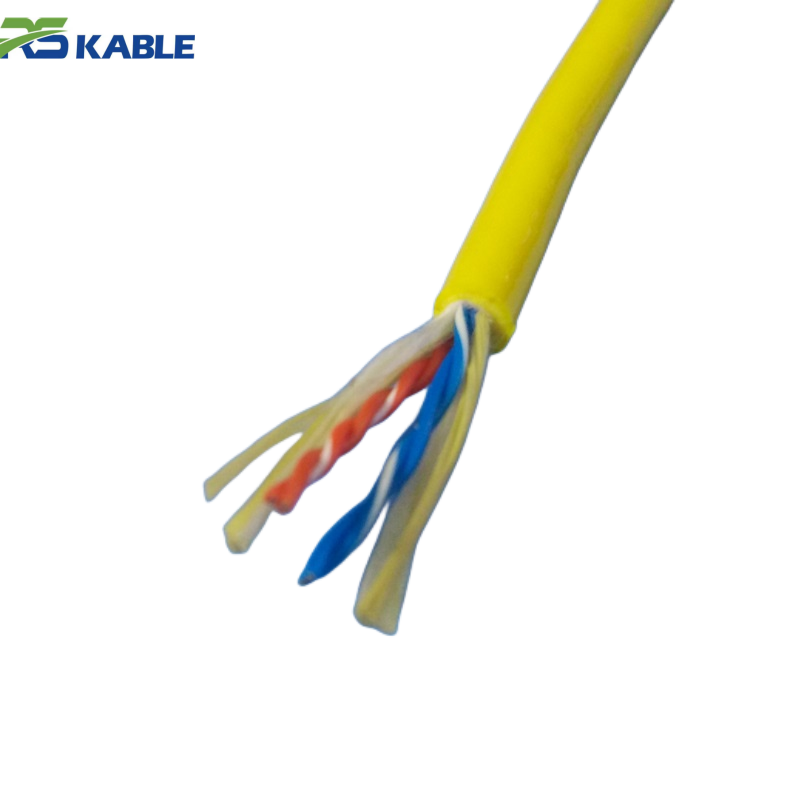
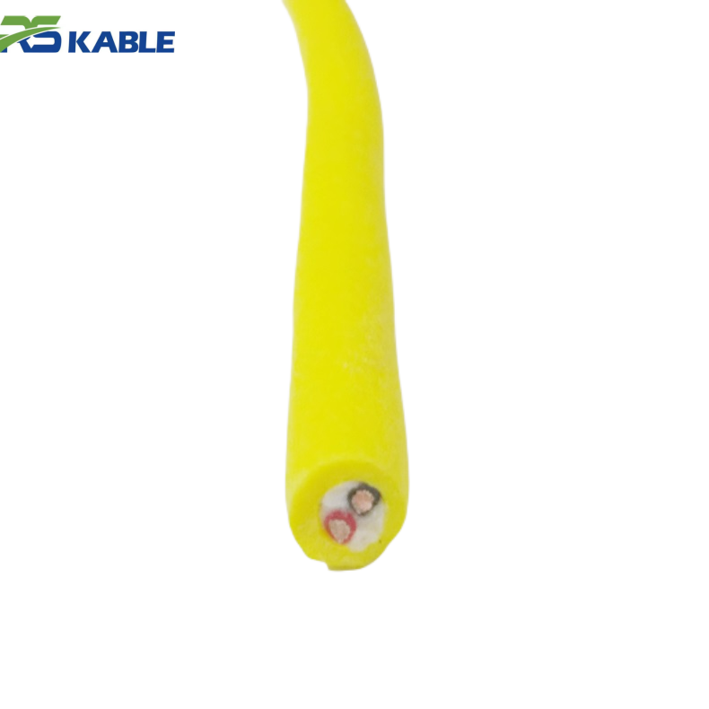
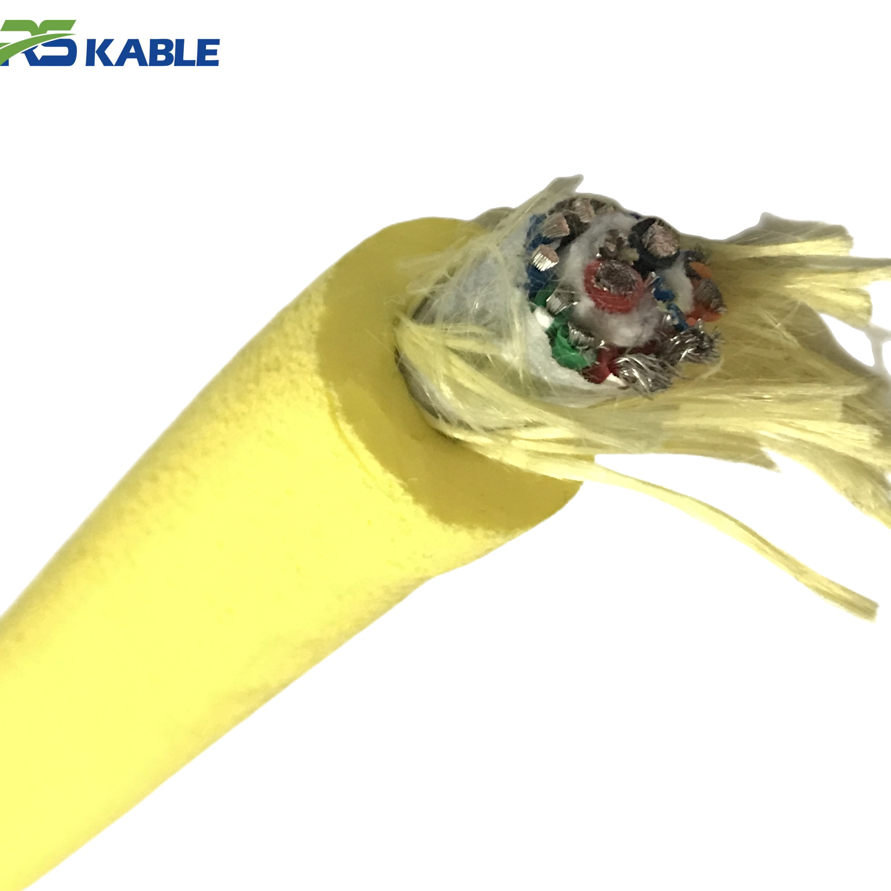
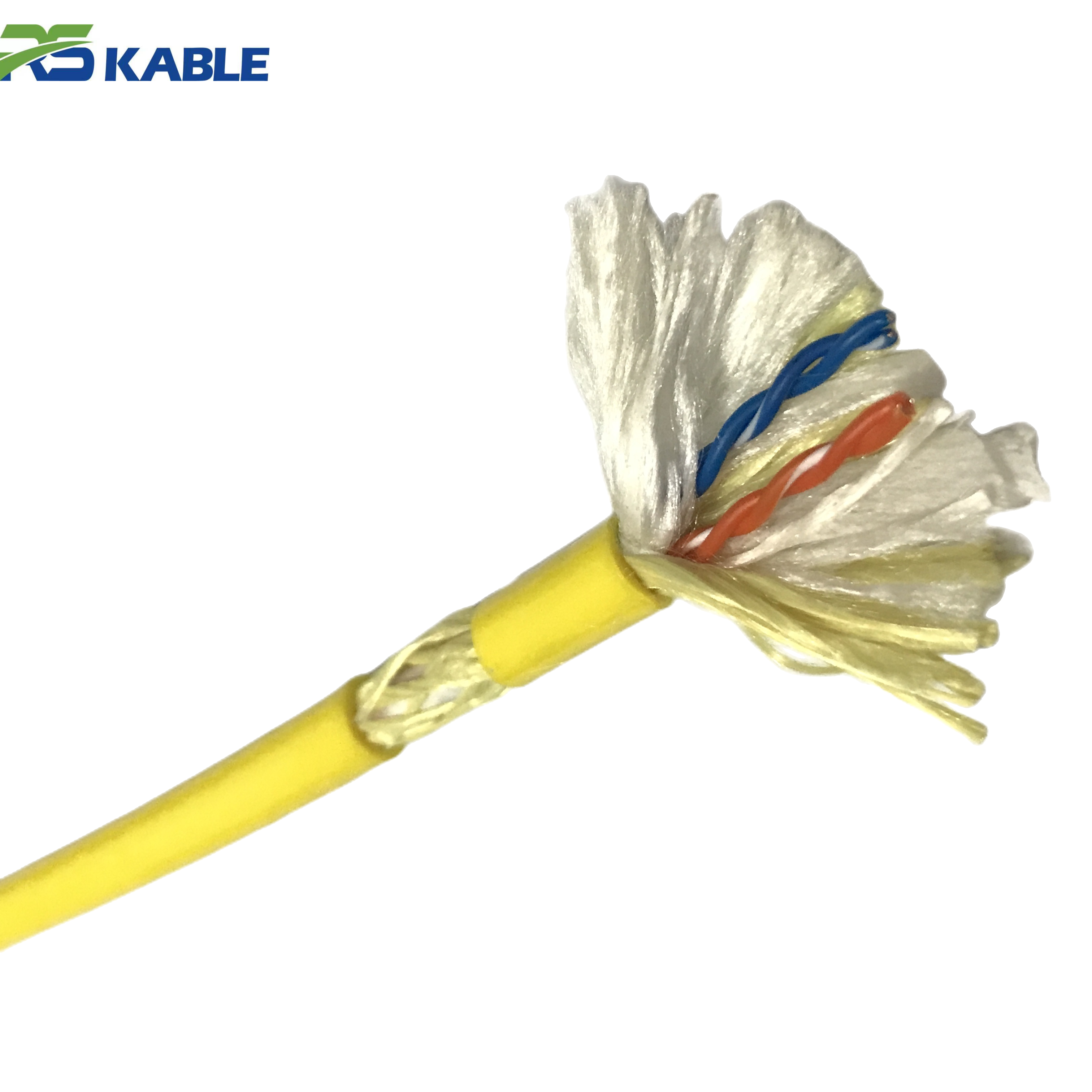
Deepwater Operations ROV Cable – Neutral Buoyancy Design, Reliable Subsea Transmission
This deepwater ROV cable features **calibrated neutral buoyancy**, a **reinforced aramid core**, and **multi-layer shielding** to ensure low drag, high tensile strength, and reliable subsea power and data transmission for offshore inspection, oil & gas, wind farm, and scientific exploration missions at depths up to 7,000 meters.
Where Offshore Cables Usually Fail First
One of the clearest differences between a generic article and a genuinely useful one is whether it identifies the places where damage most often begins. In offshore operations, failures usually do not start randomly across the entire length. They tend to appear in predictable zones.
The first high-risk zone is the termination transition area, where the flexible cable body meets the stiffer connector or breakout structure. This area sees repeated flexing, strain concentration, and sealing stress.
The second is the high-wear deck handling zone, especially the section that repeatedly passes over the same roller, fairlead, or guide point. If the same meter range always touches the same rough hardware, jacket wear accumulates quickly.
The third is the reel exit and sheave contact area, where dynamic bending and tension combine. This is often where internal conductor fatigue begins.
The fourth is the mid-span twist zone, especially if the tether is repeatedly spooled under poor tension or manually handled in rough weather.
Knowing these typical failure locations helps teams inspect smarter instead of inspecting blindly.
Failure Mode 1: Outer Jacket Abrasion
Outer sheath abrasion is one of the most common and easiest-to-recognize offshore failure modes. It is also one of the most ignored, because teams sometimes treat it as normal wear instead of a sign that the handling path is wrong.
Why it happens
Jacket abrasion develops when the tether repeatedly contacts rough or sharp surfaces. Common causes include steel guide points, worn rollers, seabed dragging, subsea frame contact, and poor alignment during launch and recovery.
Early warning signs
-
recurring scratches at the same meter mark
-
roughened or flattened outer surface
-
visible gouges or local jacket thinning
-
discoloration caused by repeated friction
-
increased drag during payout or recovery
What it can lead to
If abrasion continues, the outer sheath loses thickness and eventually stops protecting internal elements from seawater, mechanical impact, and localized compression. Once that happens, water ingress and internal damage become much more likely.
Preventive solutions
-
use abrasion-resistant outer jacket materials suited to marine handling
-
inspect repeat contact zones after every deployment
-
remove sharp edges and damaged rollers from the cable path
-
mark recurring wear points to identify handling-system problems
-
do not postpone repair of exposed or thinned jacket sections
In many offshore campaigns, abrasion damage is not really a material problem. It is a handling-system problem that shows up on the cable first.
Failure Mode 2: Internal Conductor Fatigue
A tether can look acceptable outside and still be failing electrically inside. This is one of the reasons intermittent offshore faults are so frustrating to diagnose.
Why it happens
Internal conductor fatigue is usually caused by repeated dynamic bending, torsion, or poor spooling. It becomes more likely when the cable is bent too tightly, repeatedly flexed in the same location, or used dynamically when it was designed mainly for static duty.
Early warning signs
-
intermittent power loss
-
unstable thruster behavior during movement
-
faults that appear only when the cable bends a certain way
-
brief communication dropouts during recovery
-
local heat or increased electrical resistance in one section
What it can lead to
At first, broken strands may only reduce performance under movement or load. Later, the same area can fail completely, causing unexpected mission interruption.
Preventive solutions
-
respect minimum bend radius during storage and deployment
-
use correct reel and sheave diameter for the tether design
-
avoid repeated flexing at the same unsupported point
-
include continuity and resistance checks in maintenance routines
-
investigate “movement-related faults” early instead of treating them as random
When a problem appears only while the cable is moving, internal fatigue is one of the first things worth checking.
Failure Mode 3: Water Ingress
Water ingress is one of the most damaging subsea cable problems because it can turn a small external defect into a broad internal failure.
Why it happens
Seawater usually enters through damaged outer sheath, weak end sealing, cracked connector interfaces, or impact damage near the cable end. Repeated immersion cycles make the problem worse.
Early warning signs
-
lower insulation resistance readings
-
moisture or contamination near terminations
-
corrosion at connector hardware
-
unstable signal after immersion
-
leakage or grounding alarms
What it can lead to
Once water reaches internal elements, it can cause corrosion, insulation breakdown, unstable telemetry, and progressive electrical failure.
Preventive solutions
-
repair jacket cuts immediately, even if they seem minor
-
inspect every termination before and after deployment
-
protect end sections from impact and over-bending
-
include insulation resistance testing in preventive maintenance
-
replace compromised seals rather than “watching them for one more trip”
For many subsea systems, water ingress starts at the edges of the cable system, not in the middle of the cable body.
Failure Mode 4: Termination and Connector Failure
In offshore practice, the termination is often the weakest mechanical and electrical point in the whole assembly. It combines sealing, strain relief, electrical connection, and load transfer in one compact area.
Why it happens
Common causes include poor installation, repeated flex close to the connector body, inadequate strain relief, corrosion, side-loading during deck handling, and weak sealing.
Early warning signs
-
intermittent faults near the cable end
-
visible corrosion or looseness
-
cracks in sealing or potting areas
-
power or data loss when the connector is moved slightly
-
moisture traces around sealing surfaces
Preventive solutions
-
use connector systems rated for real offshore service
-
provide proper strain relief at both ends
-
avoid tight bends close to terminations
-
inspect and clean connector interfaces on every campaign
-
treat connector maintenance as scheduled work, not optional work
A cable can be built perfectly and still fail early if the termination is poorly protected.
Failure Mode 5: Tensile Overload
In deepwater operations, one of the biggest mistakes is calculating only normal suspended weight and ignoring dynamic load. Offshore handling is rarely perfectly static.
Why it happens
Tensile overload often develops from vessel heave, shock loading during recovery, snagging, sudden winch tension, or poorly distributed load transfer at the end fitting.
Early warning signs
-
deformation near load-bearing sections
-
unusual tension behavior during recovery
-
damage concentrated near the termination transition
-
faults appearing after bad-weather deployment
-
signs of strain or elongation in reinforced sections
Preventive solutions
-
monitor line tension during launch and recovery
-
avoid shock loading during winch operations
-
confirm the strength member design matches real offshore load cases
-
review recovery procedures after every overload event
-
do not assume “no break” means “no damage”
Many cable assemblies lose service life from overload long before they experience a visible break.
Failure Mode 6: Twist, Kink, and Poor Spooling
Twist-related damage is extremely common in offshore operations, especially when deployment speed is prioritized over discipline.
Why it happens
Uneven spooling tension, uncontrolled payout, forced manual straightening, and repeated deployment without correcting cable memory all contribute to torsional stress.
Early warning signs
-
cable rotates unexpectedly during payout
-
loops form during handling
-
spiral-pattern jacket wear
-
local stiffness or kinking
-
uneven winding profile on the reel
Preventive solutions
-
maintain even tension during spooling
-
align reels and guide systems properly
-
never force twisted loops straight by hand under load
-
train deck crews to recognize early torsion signs
-
inspect the reel build after every recovery
Poor spooling is not just a cosmetic problem. It is a mechanical failure source.
Failure Mode 7: Crush and Impact Damage
Offshore decks are crowded, high-risk environments. Cables are often damaged not underwater, but during mobilization, demobilization, or day-to-day deck work.
Why it happens
Crush damage may result from dropped tools, heavy equipment placed on the tether, trapped cable under storage hardware, or poorly protected transport.
Early warning signs
-
flattened cable profile
-
local stiffness change
-
jacket distortion
-
unexplained faults after a deck incident
-
repeated damage in the same storage area
Preventive solutions
-
create dedicated cable routing and storage zones
-
do not allow the tether to become general deck traffic area
-
inspect immediately after any known impact event
-
use supports that preserve cable geometry in storage
-
train crews to treat the tether as mission equipment, not a consumable hose
Many internal failures begin with one deck incident that seemed minor at the time.
Failure Mode 8: Signal Interference and Communication Instability
Modern subsea systems depend heavily on data stability. Video, sonar, telemetry, positioning, and control feedback all rely on clean transmission.
A damaged ROV Cable may first show signal problems long before it shows total electrical failure.
Why it happens
Signal instability may result from shielding damage, poor separation between power and communication elements, water ingress, connector contamination, or internal deformation after crush or twist.
Early warning signs
-
video noise or intermittent image loss
-
telemetry spikes
-
delayed control response
-
sensor readings drifting unexpectedly
-
communication problems worsening under higher electrical load
Preventive solutions
-
use cable designs matched to hybrid power-and-data requirements
-
inspect connectors for corrosion and contamination
-
protect communication elements from crush and torsion
-
test signal integrity during scheduled maintenance
-
investigate recurring communication issues as cable issues, not only software issues
This is especially important offshore, where unstable communication can stop a task even when power remains available.
Pre-Deployment Cable Inspection Checklist
A stronger SEO article should not stop at diagnosis. It should help users act. Before deployment, teams should review:
-
outer jacket condition, especially previous wear zones
-
connector cleanliness and sealing condition
-
termination strain relief
-
reel build and spooling quality
-
bend radius compliance along the cable path
-
smoothness of rollers, sheaves, and fairleads
-
evidence of flattening, twist, or impact damage
-
basic electrical and insulation test status
This kind of checklist helps catch problems before they reach the water.
Post-Recovery Damage Checkpoints
After recovery, focus on the sections most likely to have taken damage:
-
the first high-flex zone near the termination
-
the repeated deck contact section
-
the reel exit zone
-
any meter mark that showed abrasion on prior trips
-
areas exposed to twist or poor payout
-
connector housings and seals
Documenting the exact location of wear patterns is one of the most effective ways to identify repeat failure causes.
How to Build a Preventive Maintenance Strategy
The best offshore teams combine four things:
correct cable selection
The tether must match real duty cycle, not just nominal voltage and length.
disciplined handling
Even a high-spec cable will fail early if spooling, routing, and bend control are poor.
routine testing
Continuity, insulation resistance, and signal performance checks help identify hidden damage.
failure logging
Tracking recurring meter-mark damage, overload events, and connector faults helps prevent repetition.
This is where lifecycle reliability is built. Not in one big decision, but in repeated smaller correct ones.
FAQ
What is the most common offshore ROV tether failure?
Outer-jacket abrasion is one of the most common problems because repeated offshore handling exposes the tether to rollers, steel edges, and friction.
Can internal conductor damage happen before visible outer damage?
Yes. Repeated bending and torsion can damage internal conductors even when the outer jacket still looks acceptable.
Why do subsea cable terminations fail so often?
Because they combine sealing, strain relief, load transfer, and electrical contact in one area, making them more sensitive to installation and handling errors.
How often should offshore ROV tethers be inspected?
They should be visually checked before and after every deployment, with scheduled electrical and insulation testing added to preventive maintenance.
When should a damaged cable section be repaired or retired?
If the jacket is deeply worn, sealing is compromised, conductors show intermittent faults, or damage recurs in the same zone, the section should be assessed immediately instead of left in service.