ROV Cable for Towed Systems: Catenary Control and Survey Stability
A towed ROV cable behaves nothing like a vertical deployment tether. The moment the system moves through water, the cable adopts a curved shape governed by vessel speed, water depth, cable weight, and drag forces. That curve — the catenary — determines where the sensor payload sits relative to the seabed. Get the catenary wrong and your survey data is wrong, regardless of how good your sensors are.
This article addresses the engineering of towed cable systems from a cable-first perspective. Most towed survey literature focuses on towfish hydrodynamics or GPS positioning. This article focuses on what the cable itself contributes to system performance — and on the selection and configuration decisions that determine whether a towed survey produces usable data or an expensive positioning exercise.
|
This article covers: • Catenary physics and why they matter for survey quality • Cable properties that define catenary shape • Depth control methods and depressor design • Speed, layback, and altitude trade-offs • Three real survey cases with cable specification outcomes • Selection guide for cable type by survey mission |
Not covered here: • Towfish hydrodynamics or sensor specifications • Vessel navigation and USBL positioning • Data processing or acoustic survey methodology • ROV thrusters or vehicle design This article focuses exclusively on the cable as an engineering component in towed survey systems. |
1. Catenary Physics: What the Cable Shape Tells You
The catenary is the natural curve a uniform cable takes when suspended between two points under its own weight. In a towed survey system, the “two points” are the tow point at the vessel stern and the towfish attachment. The catenary shape encodes everything about the forces acting on the cable.
The four forces in equilibrium
Four forces act on every element of a towed cable. These forces must balance at every point along the cable length for the system to reach a steady-state towing condition:
- Cable weight in water (W’). The submerged weight per unit length — the cable’s dry weight minus the buoyancy of the water it displaces. A heavier cable produces a steeper catenary and lower towfish altitude.
- Drag force (D). The hydrodynamic resistance of the cable to water flow. Drag acts along the flow direction and pushes the cable downstream and upward, reducing the catenary depth.
- Tension (T). The tensile force along the cable axis. Tension varies along the cable length — highest at the tow point, lowest near the towfish. Tension determines layback distance.
- Towfish weight and drag. The terminal load — the submerged weight and hydrodynamic drag of the sensor payload. This acts as a concentrated load at the cable’s lower end.
Layback: the positioning penalty
Layback is the horizontal distance between the vessel’s GPS antenna and the towfish’s actual position in the water. It is a direct consequence of the catenary — a deeper catenary means more horizontal cable, which means more layback.
Layback is not a constant. It changes with vessel speed, water depth, cable length deployed, and cable properties. A survey run that assumes a fixed layback offset and applies it in post-processing will have positioning errors wherever the real layback deviated from the assumed value.
|
Approximate layback: L_back ≈ L_cable × cos(θ_avg) |
Where L_cable = deployed cable length and θ_avg = average cable angle from horizontal. At a 45-degree cable angle, layback equals approximately 70% of deployed cable length. At 60 degrees (steep catenary), layback is 50% of cable length. At 30 degrees (shallow catenary), layback reaches 87% — nearly the full deployed length. |
Why altitude matters for survey quality
Towfish altitude — the height of the sensor above the seabed — directly controls the quality of side-scan sonar, sub-bottom profiler, and multibeam data. Most towfish sensors have an optimal altitude range: too high and resolution degrades; too low and the sensor risks seabed contact.
Target altitude is typically 10–20% of the swath width for side-scan sonar — for a 150 m range instrument, that is 15–30 m altitude. The catenary must be controlled precisely enough to keep the towfish within that window across the full survey line, including during turns, acceleration, and deceleration phases.
A cable that is too light or too heavy for the tow speed will place the towfish outside the altitude window. Achieving the right altitude requires matching cable properties to the operational parameters — not the other way around.
Engineering principle: The towed cable is not a passive connection between the vessel and the sensor. It is an active component of the survey system. Its mechanical properties — weight, stiffness, drag coefficient, and length — determine the towfish’s position in the water column as much as the vessel’s speed or the winch payout.
2. Cable Properties That Define the Catenary
Submerged weight per meter
Submerged weight is the most important single property of a towed cable. It is the difference between the cable’s dry linear density and the weight of water displaced by its volume:
|
Submerged weight: W’ = (m_cable − ρ_water × V_cable) × g |
Where m_cable = mass per metre (kg/m), ρ_water = seawater density (typically 1025 kg/m³), V_cable = volume per metre (m³/m), g = 9.81 m/s². A cable with W’ = 0 is neutrally buoyant. Positive W’ sinks; negative W’ rises. Most tow cables have W’ between 0.05 and 0.8 kg/m in seawater. |
Increasing submerged weight deepens the catenary at any given speed. This is the primary tool for increasing towfish depth — heavier cable goes deeper. But heavier cable also increases tow tension, which requires a larger winch and stronger tow point, and reduces cable flexibility, which affects the dynamic response of the system during maneuvers.
Drag coefficient and cable diameter
Drag force per unit length on a cylindrical cable depends on flow velocity, cable diameter, and the drag coefficient Cd. For smooth cylindrical cables in turbulent flow, Cd is approximately 1.0–1.2. The drag force is:
|
Drag force (per metre): D = ½ × ρ × V² × D_cable × Cd |
Where ρ = water density, V = tow speed (m/s), D_cable = cable outer diameter (m), Cd = drag coefficient. At 3 knots (1.54 m/s) with a 20 mm cable, drag force is approximately 19 N/m. A 10 mm cable at the same speed generates only 9 N/m of drag — less than half. Cable diameter is a powerful variable in catenary control. |
A thin cable with high submerged weight dives steeply and generates little drag. A fat cable with low weight flies high and generates large drag. The combination of these two properties — not either one alone — defines the catenary behavior at a given tow speed.
Torsional stability
A towed cable under tension develops torsional moments from the hydrodynamic loading asymmetry. An unstable cable rotates under tow — this rotation transmits to the towfish as a roll oscillation, which creates attitude instability in the sensor data.
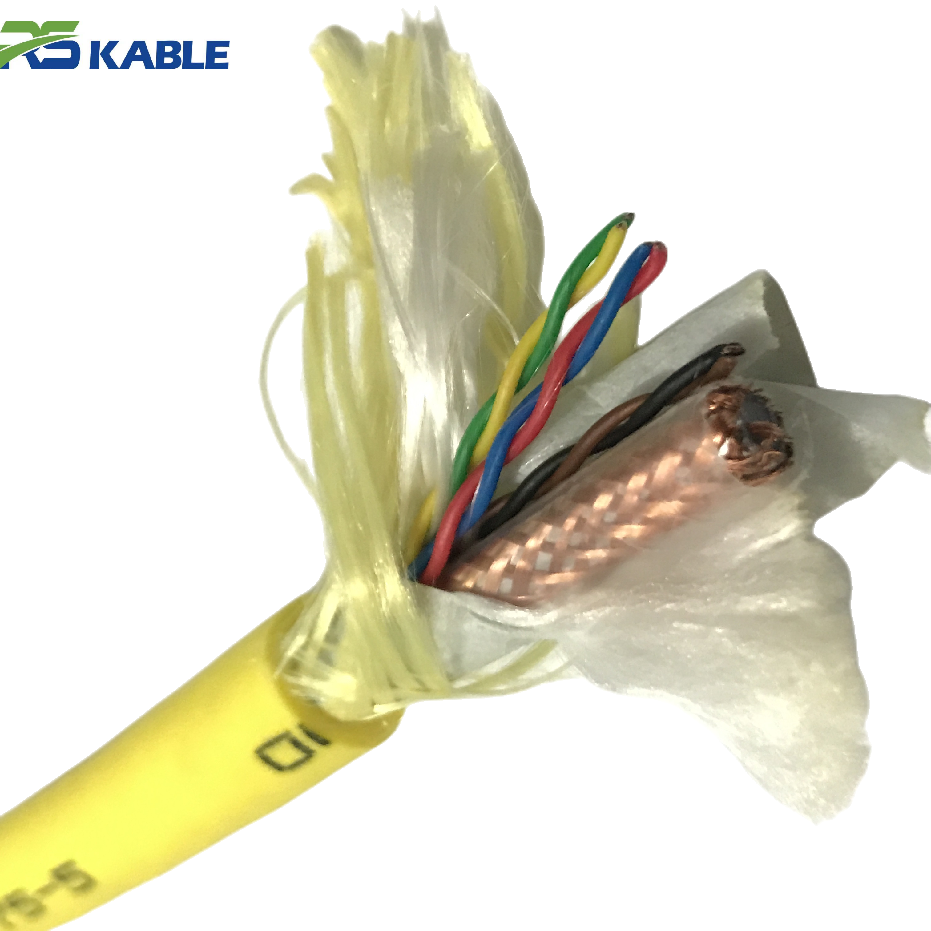
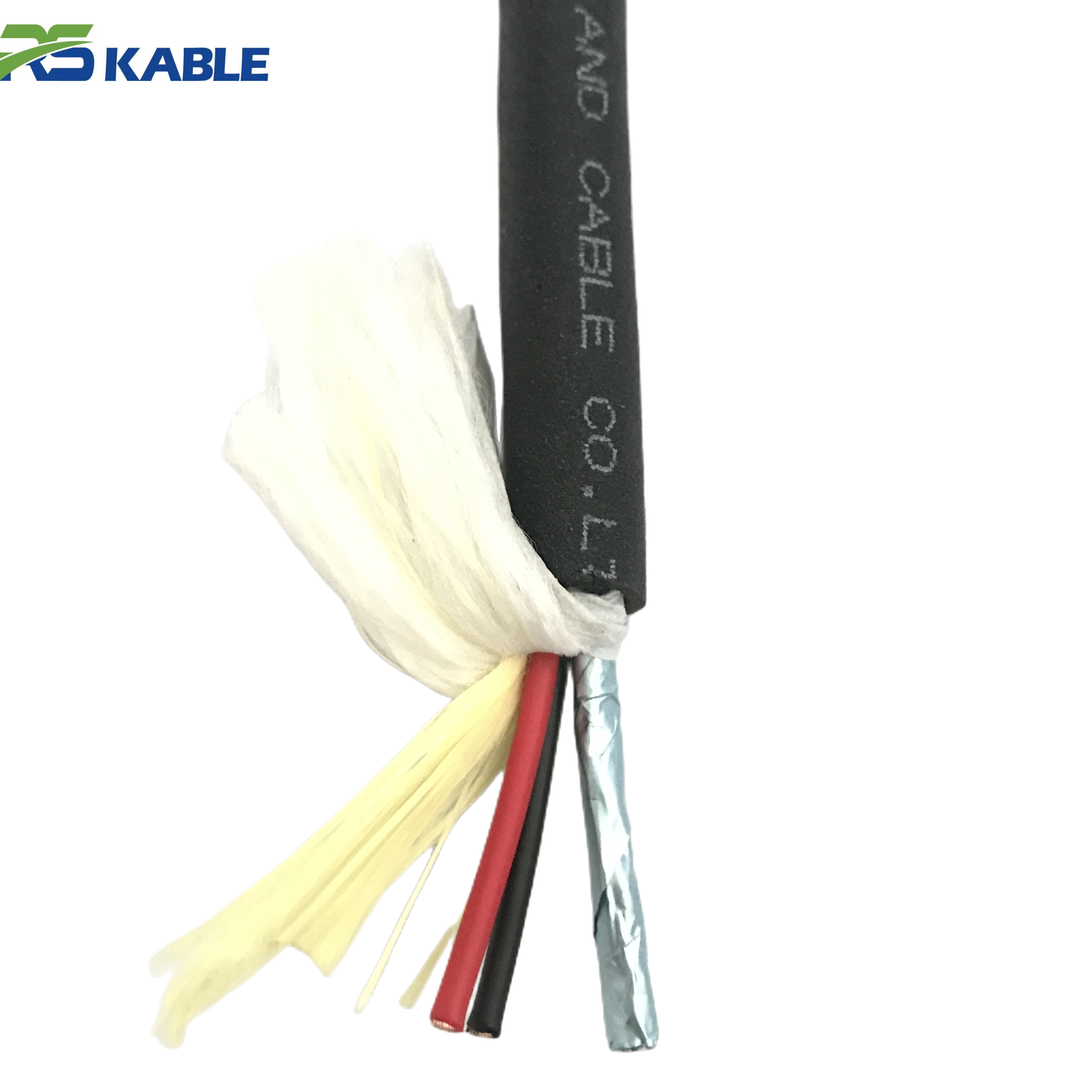
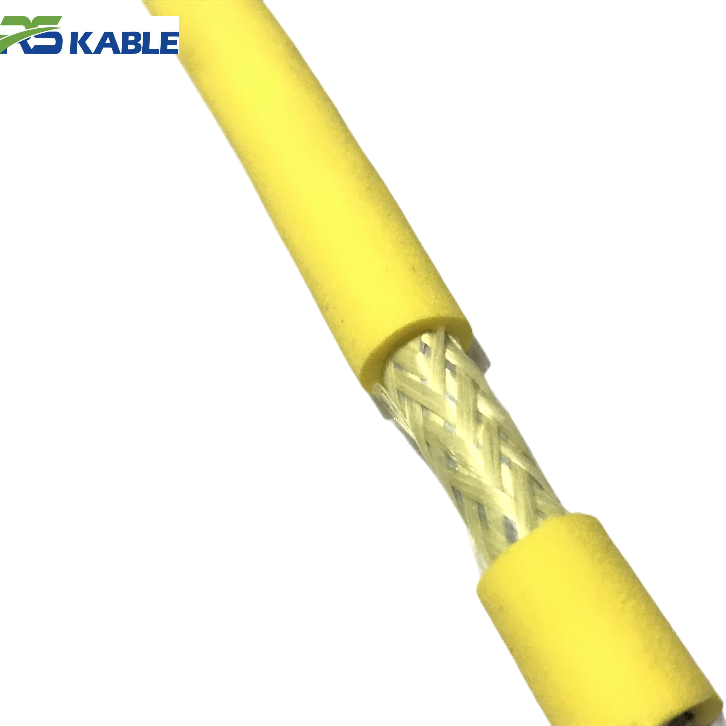
Torsionally balanced cables use counter-wound armor layers to cancel the rotation tendency under load. This is a standard feature on purpose-built tow cables. It is absent on ROV tethers designed for static or low-dynamic deployment — which is one reason standard ROV tethers perform poorly in towed applications.
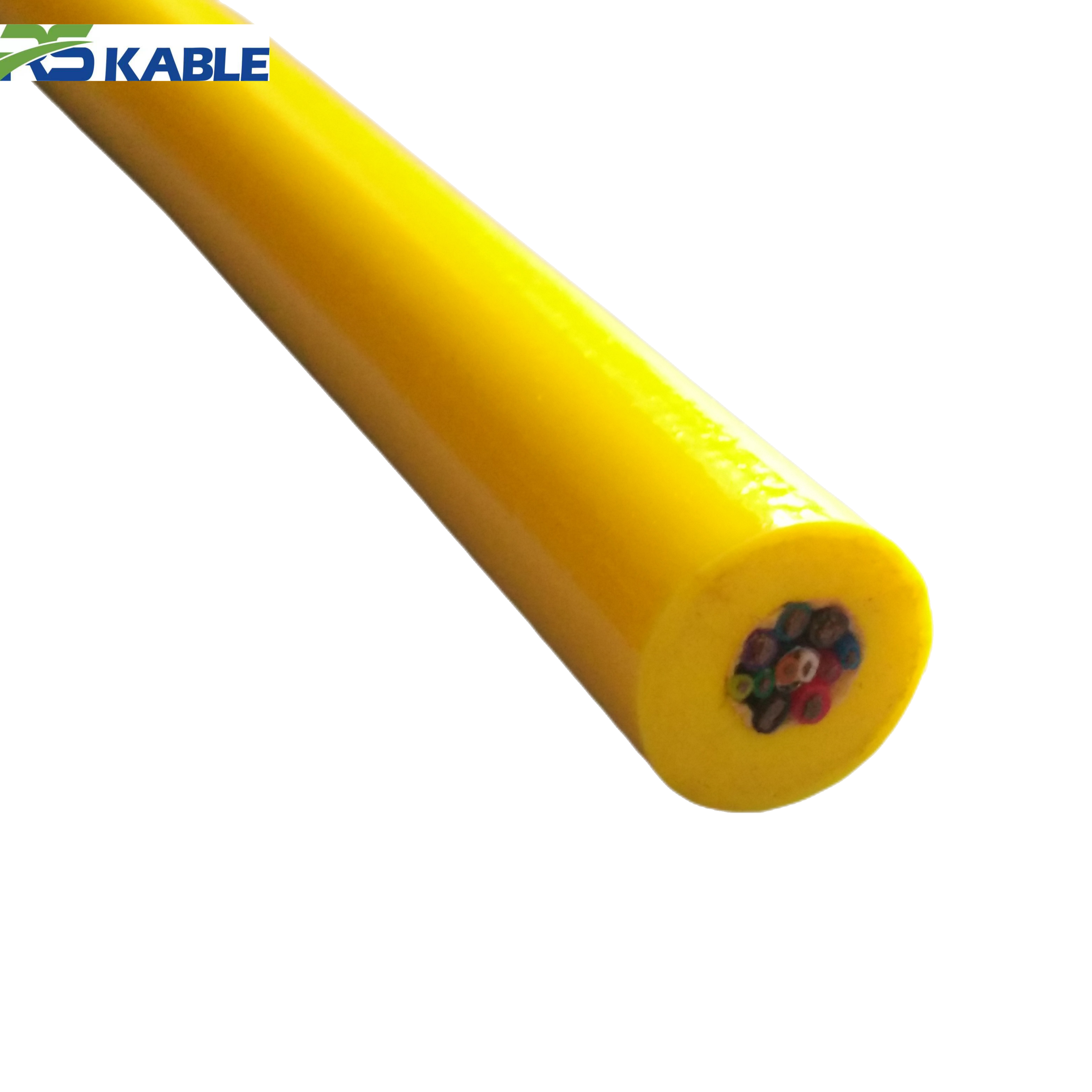
Electrical and optical conductor configuration
Towed survey cables carry power to the towfish and return data to the surface. The conductor configuration is constrained by the same weight and diameter trade-offs as the mechanical design:
|
Data type |
Conductor choice |
Advantage |
Constraint |
|
Standard definition video |
Coaxial (75Ω) |
Low weight, simple termination |
Bandwidth limited to ~6 MHz |
|
HD video / sonar data |
Shielded twisted pair (STP) |
Higher bandwidth, flexible |
Sensitive to impedance mismatch |
|
High-bandwidth sonar |
Single-mode optical fiber |
Unlimited bandwidth, EMI-immune |
Fragile bend radius, specialist termination |
|
Power (LV, short range) |
Copper pair (1.5–4 mm²) |
Simple, low cost |
Voltage drop at long range |
|
Power (HV, long range) |
Copper pair (0.75–1.5 mm²) at HV |
Low current, less weight |
HV isolation required, safety controls |
Table 1. Conductor configuration options for towed survey cables. The choice of conductor type affects both the cable’s electrical performance and its mechanical properties — heavier conductors deepen the catenary.
3. Depth Control Methods
A towed survey system has four methods of controlling towfish depth. Each method works through a different mechanism. Understanding which mechanism is active allows you to predict how depth will respond to changes in tow speed, cable payout, and sea state.
Method 1 — Cable payout length
Paying out more cable increases the catenary length and lowers the towfish. This is the most direct depth control method. It is also the slowest — depth response to payout changes has a time constant measured in minutes for deep survey systems, because the catenary must equilibrate to the new cable geometry.
Payout control is the primary depth control method for deep-tow systems where the towfish operates at 50–80% of water depth. It becomes impractical as the required depth approaches the full cable length — you cannot pay out more cable than the winch holds.
Method 2 — Vessel speed
Increasing vessel speed raises the towfish by increasing drag on the cable and towfish. Decreasing speed allows the towfish to sink. Speed-based depth control has a faster time constant than payout control — depth responds within 1–2 minutes of a speed change.
The trade-off is survey productivity. Reducing speed to deepen the towfish also reduces line coverage rate. On tight survey schedules, depth control through speed change has a direct cost in survey time. For this reason, deep-tow systems use payout control for slow, coarse depth adjustments and speed changes for fine, rapid corrections.
Method 3 — Depressor weights and wings
A depressor is a hydrodynamic device or dead weight attached to the cable at a calculated midpoint. It adds concentrated downward force to the cable, deepening the catenary below the depressor attachment point. Wings — horizontal foil surfaces attached to the cable — generate lift or downforce depending on their angle of attack.
Depressors are preferred over dead weights for their adjustability. A depressor with adjustable wing angle can be trimmed to maintain constant depth over a range of tow speeds — dramatically improving altitude control on variable-speed survey lines. Fixed dead weights require a payout change to maintain depth when speed changes.
Method 4 — Active heave compensation
Active heave compensation (AHC) systems use a controlled winch to pay out and recover cable in real time, compensating for vessel motion in waves. They maintain a nearly constant cable payout length despite ship heave, which stabilizes the towfish altitude in rough sea conditions.
AHC is most valuable in open-ocean deep-tow work where swell periods are long (8–14 seconds) and heave amplitudes are large (2–5 m). For shallow coastal survey in calm conditions, the added cost and complexity of AHC is rarely justified. For deep-sea geophysical survey programs, it is often the difference between usable and unusable data in typical sea states.
Field note: A geophysical survey program in the South China Sea used a 3,500 m tow cable with a 300 kg steel depressor at the 2,800 m mark. In 1.5 m swell conditions without AHC, towfish altitude varied ±18 m across a survey line. With AHC engaged, altitude variation reduced to ±3 m. The sub-bottom profiler data quality improvement was immediately visible in the survey records — layer resolution increased from approximately 0.5 m to 0.1 m.
4. The Speed–Layback–Altitude Triangle
Speed, layback, and altitude are not independent variables in a towed system. Changing one changes the others. Optimizing survey operations requires understanding the relationships between all three simultaneously.
How speed affects altitude and layback together
Increasing tow speed has two competing effects on the catenary. Higher drag pushes the cable upward, raising towfish altitude. But higher drag also straightens the cable, reducing its catenary depth and shifting the curve toward the horizontal — which increases layback.
For a typical survey cable at 2–4 knot tow speeds, a 1-knot speed increase raises towfish altitude by approximately 5–15% and increases layback by 8–12%. These ratios vary with cable properties and deployed length — they must be characterized empirically for each specific cable and towfish combination before the survey begins.
The optimal tow speed window
Every towed survey system has an optimal speed window — a range of tow speeds where the towfish altitude stays within the target range and layback remains small enough for acceptable position uncertainty. Outside this window:
- Too slow: towfish sinks below minimum altitude, risks seabed contact, altitude accuracy degrades.
- Too fast: towfish rises above maximum altitude, swath resolution decreases, coverage efficiency declines.
The speed window is narrower than most operators expect. For a well-matched cable-towfish combination, it is typically 0.8–1.5 knots wide. For a poorly matched combination — wrong cable weight or diameter for the depth — the window may not exist at the target depth.
Quantifying position uncertainty from layback
Layback introduces position uncertainty in the survey data. The uncertainty arises from two sources: inaccuracy in the assumed catenary model (the difference between the modeled and actual cable shape), and real-time variations in layback as speed, depth, and sea state change.
|
Position uncertainty: σ_pos ≈ σ_speed × ∂L_back/∂V + σ_depth × ∂L_back/∂h |
Where σ_speed = speed measurement uncertainty (m/s), σ_depth = depth measurement uncertainty (m), and the partial derivatives describe how sensitive layback is to speed and depth changes. For survey-grade positioning, layback sensitivity must be characterized from in-water tests — not from manufacturer specifications alone. |
5. Three Survey Cases: Cable Specification Outcomes
The following cases are drawn from towed survey programs where the cable specification was a determining factor in mission outcome. Each case illustrates a different dimension of the cable-catenary relationship.
|
CASE 01 |
Site: Shallow-water pipeline route survey, 15–45 m depth, 2.5-knot tow speed, side-scan sonar towfish |
|
Problem: Standard ROV tether used as tow cable. Towfish altitude unstable — varying from 2 m to 22 m on the same line. Survey data unusable at low-altitude sections due to near-field effects. Cable rotating visibly at stern sheave — no torsional stability. |
|
|
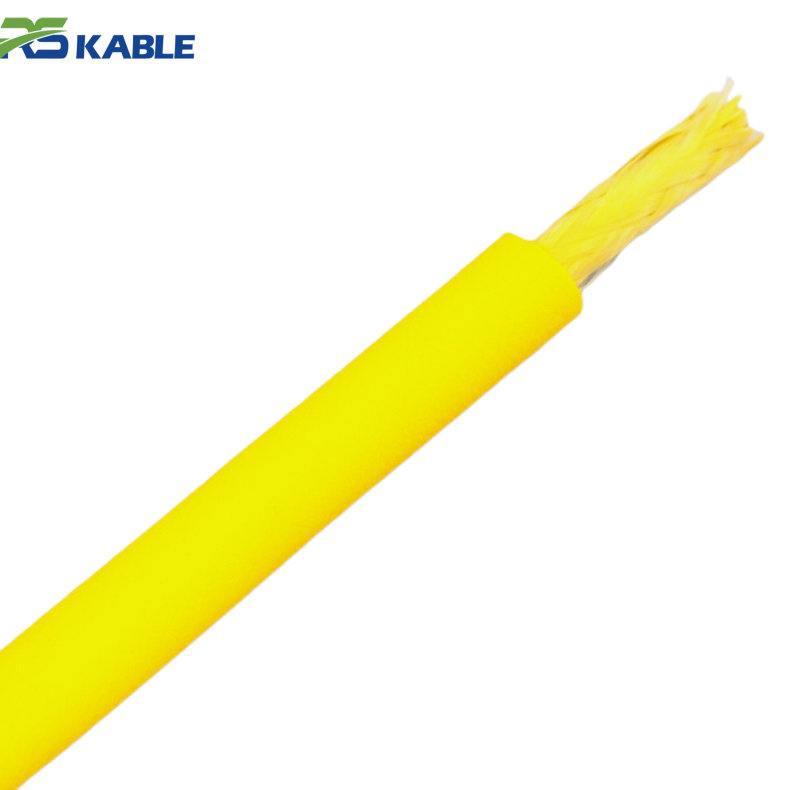
Solution: Replaced with purpose-built tow cable: 10 mm OD, W’ = 0.12 kg/m in seawater, torsionally balanced double-armor construction. Depressor wing fitted at 40 m from towfish. |
|
|
Outcome: Altitude stabilized at 8–12 m throughout survey lines. Towfish rotation eliminated. Full 120 km survey route completed in planned 4-day program. Previous attempt with ROV tether had been aborted after day 1. |
|
CASE 02 |
Site: Deep-sea cable route survey, 800–2,200 m depth, sub-bottom profiler + side-scan sonar, 3-knot tow speed |
|
Problem: Cable specified at W’ = 0.45 kg/m. At 2,200 m depth with 3,200 m cable payout, modeled altitude was 50 m. Actual altitude measured at 95–110 m — nearly double the model. High altitude caused sub-bottom profiler to operate at 2× the designed energy level. Signal penetration reduced from 40 m to 18 m. |
|
|
Solution: Investigation revealed the catenary model had used dry cable weight instead of submerged weight. Actual W’ was 0.22 kg/m — less than half the specified value. Cable replaced with correct specification. Survey repeated at corrected altitude. |
|
|
Outcome: Sub-bottom penetration restored to 38 m. Complete geological layer mapping achieved to project specification. Root-cause was a single data entry error in the catenary model — submerged weight, not dry weight. |
|
CASE 03 |
Site: Offshore wind site survey, 30–60 m depth, 4-knot maximum tow speed due to vessel constraint, multibeam sonar towfish |
|
Problem: Cable correctly specified for 4 knots. At the required 15 m altitude, layback calculated at 420 m for 500 m cable payout. USBL positioning system had a maximum range of 350 m — towfish outside USBL range during entire survey. |
|
|
Solution: Cable specification changed to higher W’ (0.35 kg/m from 0.18 kg/m). Required cable payout for 15 m altitude at 4 knots reduced from 500 m to 310 m. Layback reduced to 240 m — within USBL range. |
|
|
Outcome: Complete acoustic positioning coverage achieved. Heavier cable required 15% increase in tow tension, within vessel A-frame and winch capacity. Survey completed with sub-metre position accuracy throughout. |
6. Cable Selection Guide by Survey Mission
The following table consolidates the engineering principles above into practical starting specifications for four common towed survey mission types. These are starting points — each deployment requires a catenary model to verify depth and altitude performance before the survey begins.
|
Mission type |
Target depth |
Tow speed |
Cable spec |
Key considerations |
|
Shallow coastal side-scan |
5–50 m |
2–4 knots |
8–12 mm OD, W’=0.08–0.18 kg/m |
Torsional balance critical; depressor wing for altitude control; short layback needed for coastal position accuracy |
|
Mid-water sonar survey |
50–300 m |
2–5 knots |
14–18 mm OD, W’=0.20–0.40 kg/m |
HV power if depth > 150 m; AHC if swell > 1.5 m; layback model essential for positioning |
|
Deep-tow geophysical |
300–3,000 m |
1.5–3 knots |
20–26 mm OD, W’=0.40–0.80 kg/m |
Steel armor for tensile capacity; HV power mandatory; AHC strongly recommended; depressor for altitude trim |
|
UXO / mine countermeasure |
5–30 m |
3–6 knots |
6–10 mm OD, W’=0.05–0.12 kg/m |
Maximum torsional stability required; low drag for high-speed stability; fiber optic data for magnetic cleanliness near sensors |
Table 2. Cable starting specifications by survey mission type. All values assume standard seawater density (1025 kg/m³). Verify with full catenary model before deployment. W’ = submerged linear weight.
The catenary model: minimum viable calculation
Every towed survey deployment should be preceded by a catenary model. A full finite-element catenary analysis is the gold standard. But a simplified two-segment model — treating the cable as two straight segments from the tow point to the depressor and from the depressor to the towfish — is adequate for planning purposes in most shallow and mid-water applications.
The minimum inputs required are: cable submerged weight per meter, cable drag coefficient and diameter, depressor weight and drag, towfish weight and drag, tow speed, and target towfish altitude. The outputs are: required cable payout length, expected layback distance, and tow tension at the vessel.
Free catenary calculation tools are available from the Society of Underwater Technology and several national hydrographic offices. If your survey program does not include a catenary model, the survey’s depth accuracy and positioning accuracy cannot be reliably predicted.
7. Cable Design Is Survey Design
The interdependence you cannot ignore
A towed ROV cable is not a procurement line item. It is a component of the survey measurement system. Its mechanical properties define the towfish’s position in the water column as directly as the vessel’s speed or the winch payout. Specifying it without a catenary model is equivalent to specifying a GPS antenna without a positioning accuracy requirement — technically possible, operationally meaningless.
The cases in Section 5 share a common thread. In each one, the cable was specified without a full understanding of how its properties would interact with the tow speed, target depth, and positioning requirements. The consequences ranged from unusable data to a complete survey abort. In every case, the correct cable specification was knowable in advance. The catenary model would have identified the problem before the vessel left the dock.
What changes when you treat the cable as a system component
When the cable enters the survey design process as a system component rather than an afterthought, three things change.
First, the optimal tow speed window is calculated before the survey begins. The vessel operations team knows exactly what speed range maintains acceptable altitude — not from experience on the previous program, but from the physics of this cable, this towfish, and this depth.
Second, layback is modeled as a function of operational parameters. The survey data processor receives a layback lookup table that captures position uncertainty across the actual operating conditions — not a fixed offset.
Third, the depressor specification is engineered, not improvised. Weight, wing angle, and attachment point are calculated to maintain target altitude across the full speed range, not installed based on what was available in the deck locker.
These three changes require perhaps four to eight hours of additional pre-survey engineering. They save a multiple of that time in data quality assurance, repositioning runs, and post-processing correction effort. For any survey program longer than two days, the return on that investment is not debatable.
Specifying a cable for a towed survey program? Our engineering team supports towed cable specification with catenary modeling, submerged weight calculation, and conductor configuration design. Send your target depth, tow speed, towfish weight, and data requirements. We will return a written cable specification with a simplified catenary model and layback estimate.
Frequently Asked Questions
Q1: Can I use a standard ROV tether as a tow cable?
Standard ROV tethers are designed for dynamic bending and vertical deployment — not for sustained towing under tension. The two critical properties they lack for towed applications are torsional balance and optimized submerged weight. A standard ROV tether has a helical armor wound in one direction. Under towing tension, it rotates — transmitting roll oscillation to the towfish. This alone makes towed ROV cable performance with a standard tether unreliable for survey-grade data collection, as shown in Case 01. Some low-speed, shallow-water applications may tolerate a standard tether with a swivel attached between the cable and towfish — but this is a compromise, not a solution. Purpose-built tow cables with counter-helical armor are the correct specification for any survey where data quality matters.
Q2: How do I calculate the correct cable payout for a target towfish depth?
The calculation requires an iterative catenary model that balances the four forces described in Section 1. For a simplified approach, use the following procedure: estimate the average cable angle θ from the target depth and estimated layback (start with layback = 60% of target depth); calculate required cable length as target_depth / sin(θ); check whether the resulting layback is consistent with the assumed value; iterate until consistent. For depths greater than 200 m or when precision positioning is required, use a finite-element catenary model rather than the simplified two-segment approach. The accuracy difference is significant at long cable deployments.
Q3: What is the maximum tow speed for a fiber optic tow cable?
Maximum tow speed for a fiber optic cable is not limited by the fiber itself — optical fiber has no speed-dependent performance degradation. The limit comes from two other factors. First, the hydrodynamic loads on the cable at high speed generate tension that must not exceed the cable’s rated tensile strength — typically 5–20 kN for survey tow cables depending on armor design. Second, the dynamic bending of the cable at high speed must not exceed the fiber’s minimum bend radius — a limit that is determined by the cable’s mechanical design, not the fiber’s optical properties. Most purpose-built tow cables with optical fiber are rated to 6–8 knots. Beyond this, consult the manufacturer’s tension and bending specifications for the specific cable design.
Q4: How does sea state affect tow cable performance?
Sea state affects tow cable performance through two mechanisms: heave and pitch motion of the vessel, and surface wave orbital velocities. Vessel heave imparts cyclic tension changes in the cable at the heave period — typically 6–14 seconds for ocean swell. Each heave cycle produces a tension spike at the tow point and a corresponding slack condition at the cable’s lower end. This creates altitude oscillation in the towfish. For significant wave heights above 1.5 m, altitude variation without AHC typically exceeds the towfish’s optimal altitude window for side-scan and sub-bottom survey. Surface wave orbital velocities affect the catenary shape in shallow water — at depths shallower than half the wave length, wave-driven water motion perturbs the cable from its steady-state catenary geometry.
Q5: Is a coaxial cable or fiber optic cable better for high-speed tow applications?
For high-speed applications above 4 knots, fiber optic has two practical advantages over coaxial. First, fiber carries higher bandwidth — modern sonar systems generating 100+ Mbps data rates cannot be supported by coaxial at any practical tether length. Second, fiber is smaller and lighter than coaxial at equivalent bandwidth, which reduces cable diameter and drag — both of which matter at high tow speeds. The disadvantage of fiber at high tow speeds is termination fragility — repeated mechanical stress at the termination point from high-speed cable dynamics can cause fiber breakage at splice points over time. High-speed tow cable fiber terminations require strain relief designs that accommodate dynamic bending at the connectors. This is a specialist termination — not all cable manufacturers offer it to an adequate standard.
Q6: How often should a tow cable’s catenary model be recalibrated?
Recalibrate the catenary model whenever any of the following conditions change: the cable is replaced or repaired (material properties may differ between cable batches); the towfish configuration changes (different sensor payload means different weight and drag); the survey area has significantly different water density than the model assumption (temperature and salinity affect seawater density and therefore submerged cable weight); or in-water measurements consistently differ from model predictions by more than 10% in altitude. In practice, a well-characterized cable-towfish combination on a repetitive survey program (such as annual pipeline inspection) can be re-used from year to year with only a pre-season verification dive — a short in-water test at the target depth to confirm the catenary model still matches observed altitude and layback.