ROV Cable Failure Modes: Common Causes and Preventive Maintenance Checklist
Cable failures in ROV work almost never arrive with a clean, obvious break. They usually arrive as nuisance symptoms: a brief video glitch during a turn, a power reset that only happens under heavy thrust, a section of tether that suddenly feels “stiffer,” or jacket wear that appears in the same place after every job. Left alone, those nuisances become downtime—often at the worst moment in the shift.
This article is a field-focused breakdown of how ROV tethers fail, why they fail, and how to stop small defects from turning into mission-stopping faults. It includes a practical maintenance schedule, clear “stop/monitor/continue” rules, and early-warning cues crews can recognize without special equipment.
What to watch first: a short list of high-signal warning cues
If you want the fastest way to catch problems early, look for these five cues during normal operations and handling:
-
Movement-only faults (video or telemetry drops only while moving)
-
Repeat wear in the same location (same drum zone, same fairlead, same sheave)
-
A new hard spot (stiff section you can feel while paying out or recovering)
-
“Sticky” tether behavior (cable hesitates or “holds” during turns—often contact friction)
-
Connector ends that look or feel different (cracks, sudden stiffness change, damaged overmold)
Those cues correlate strongly with real root causes and are worth treating as action triggers, not background noise.
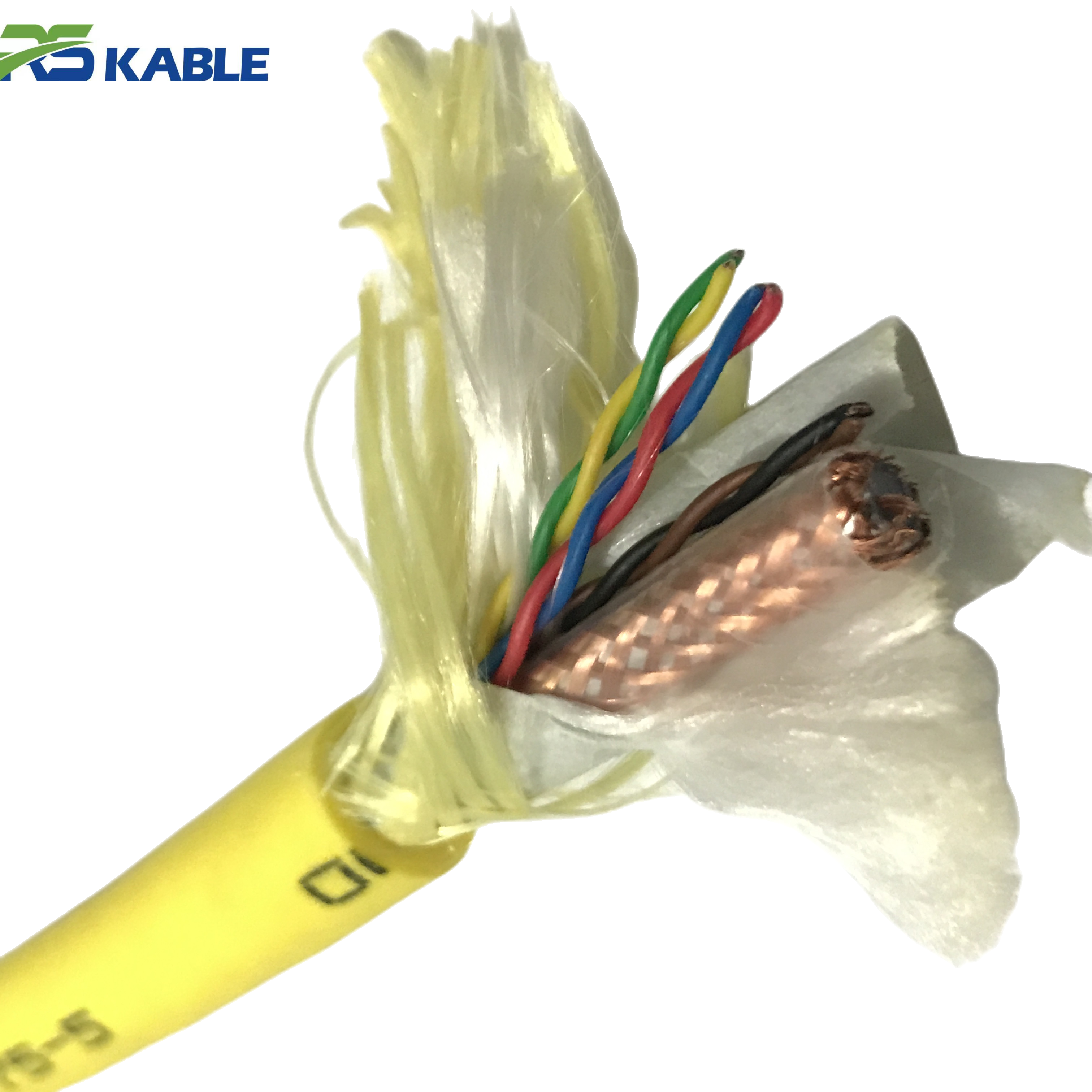
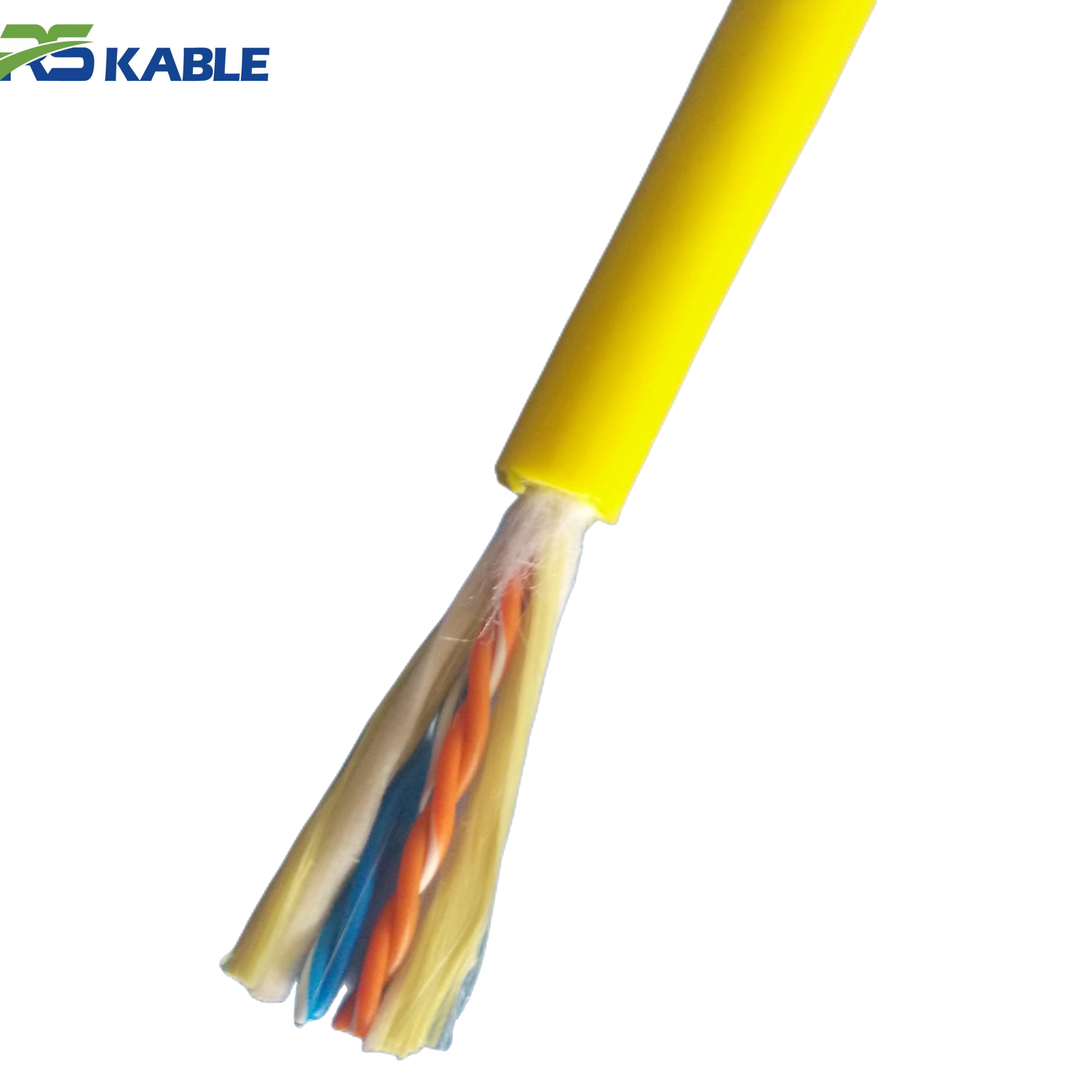
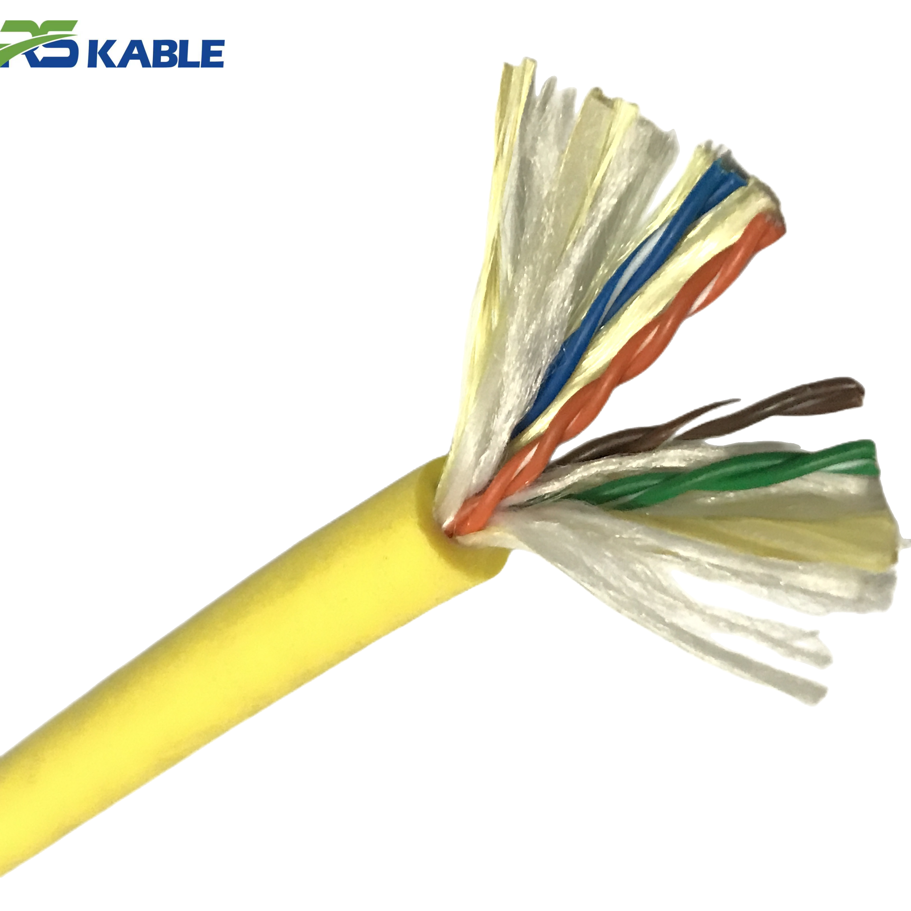
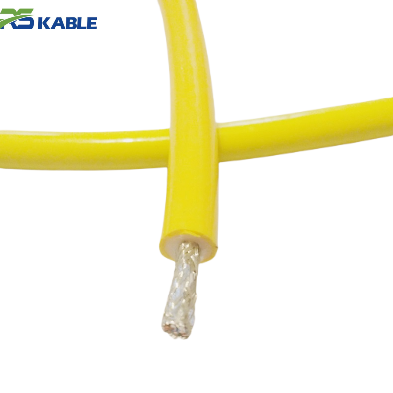
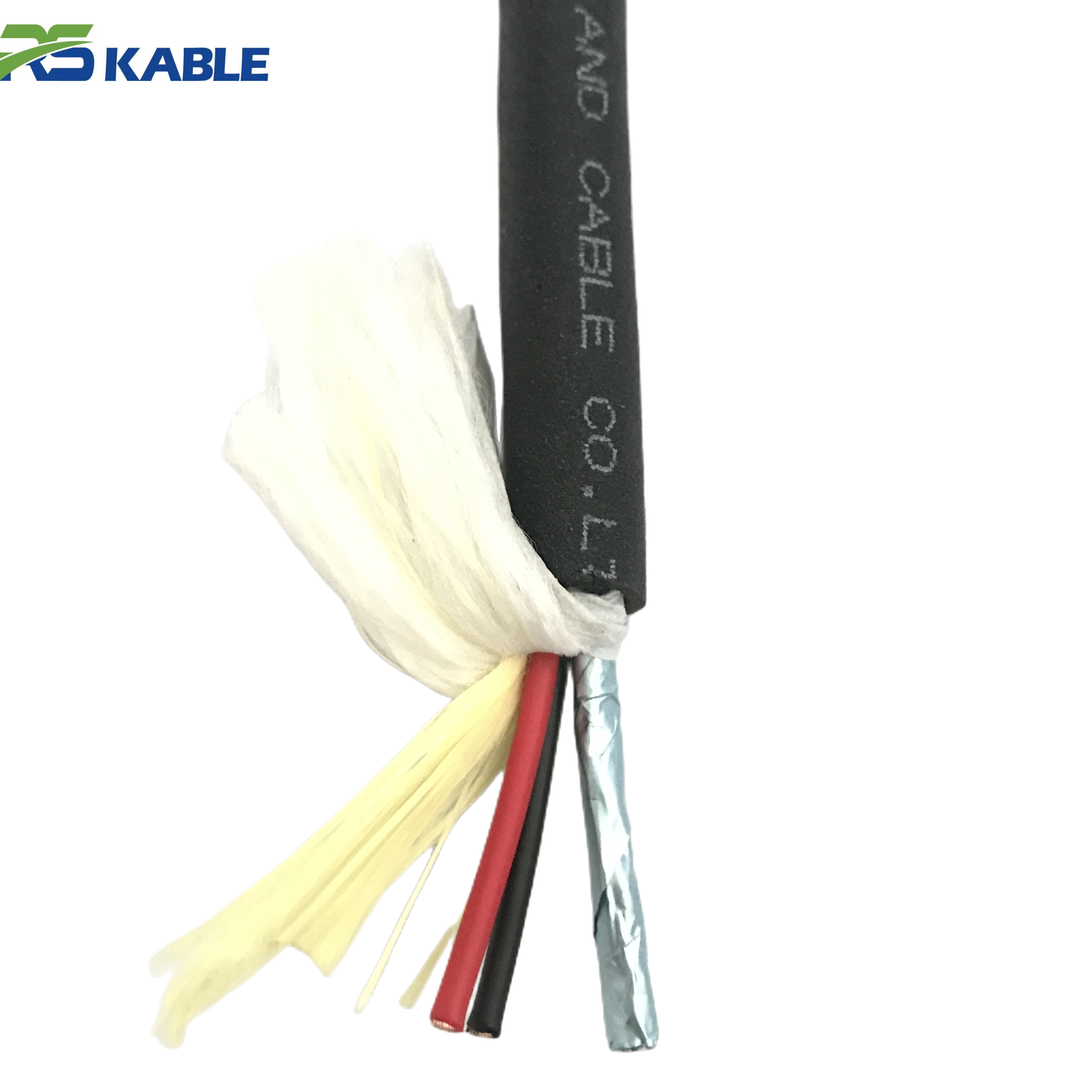
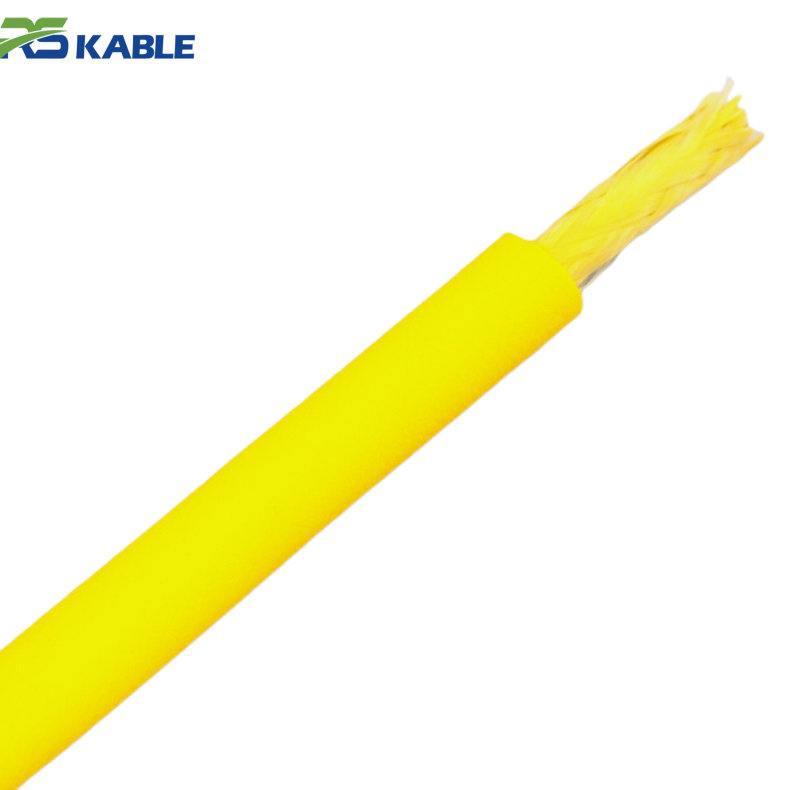
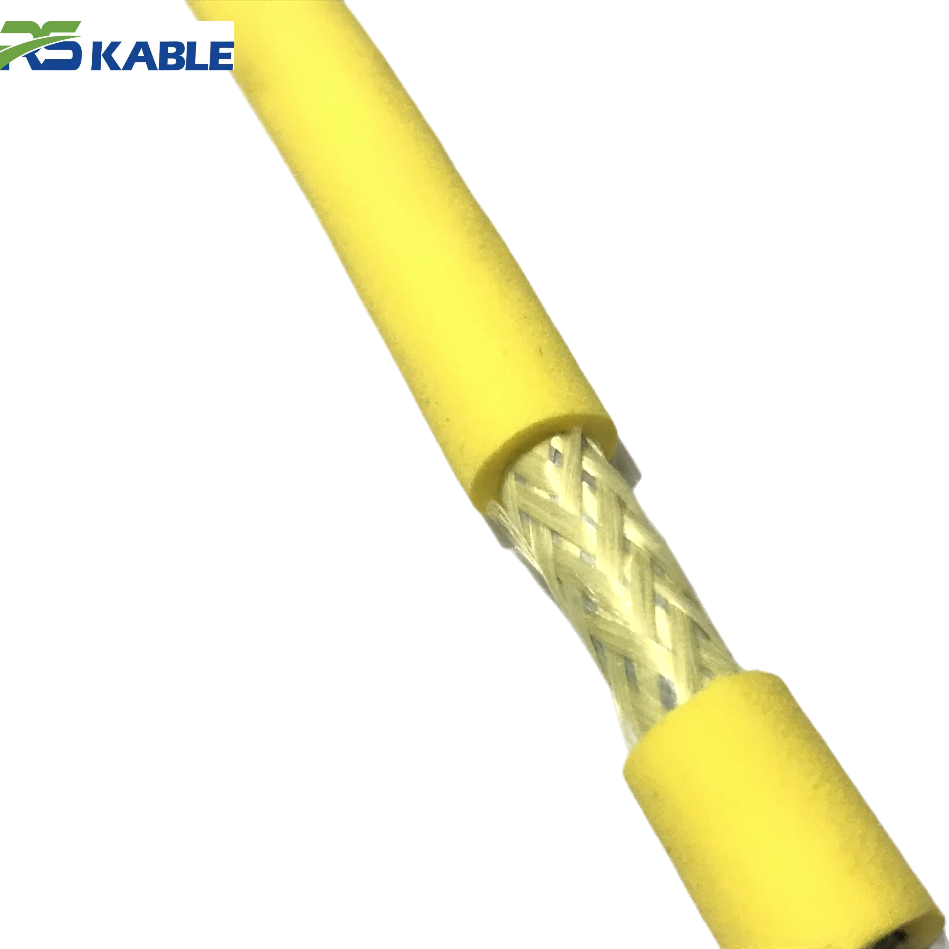
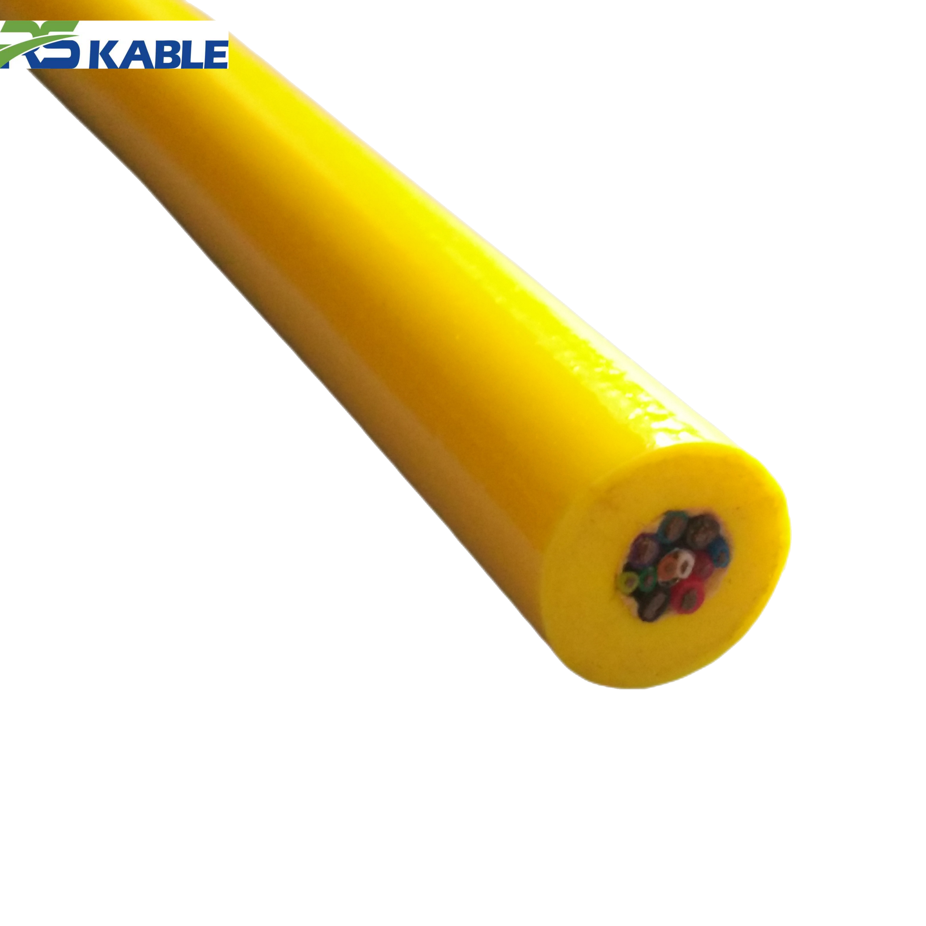
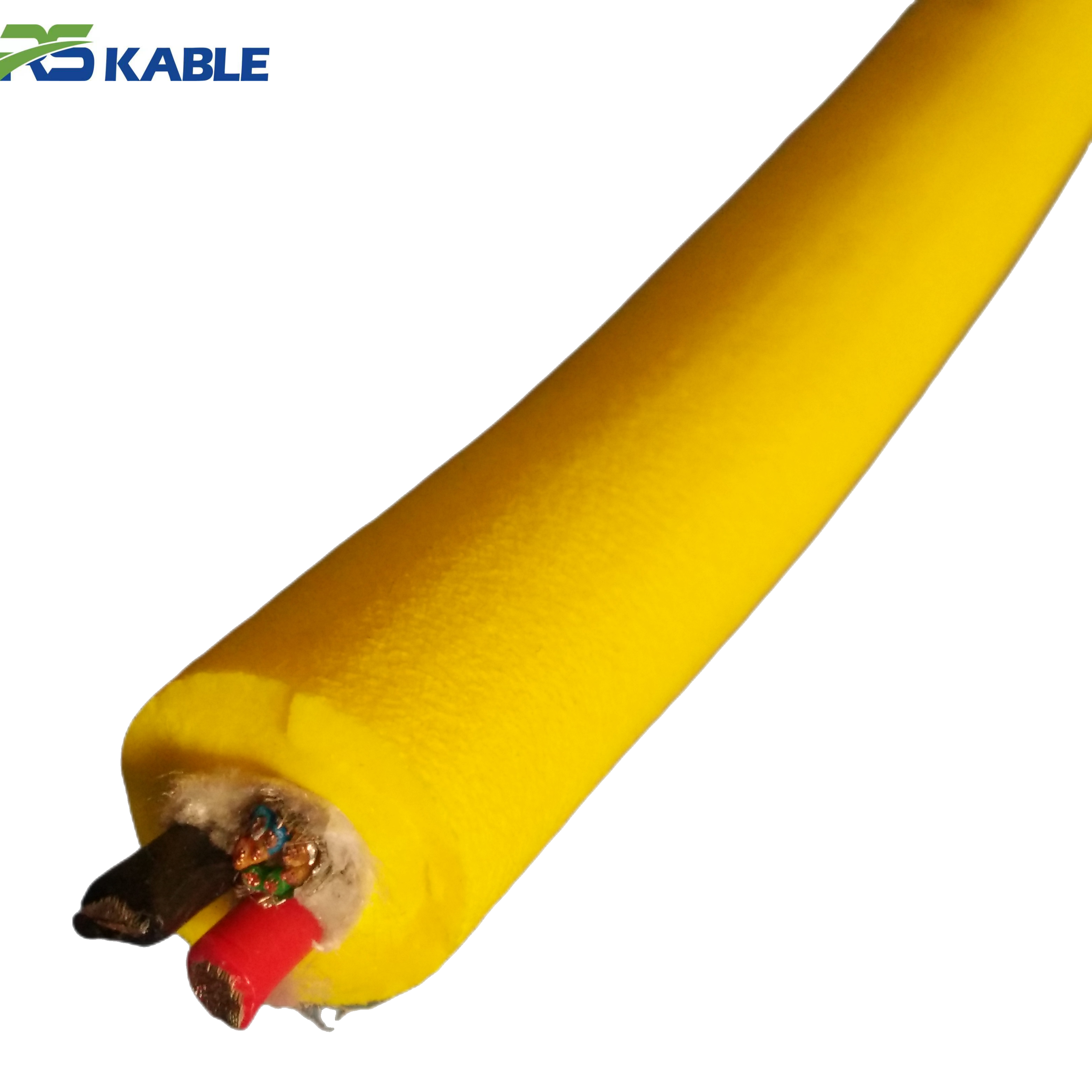
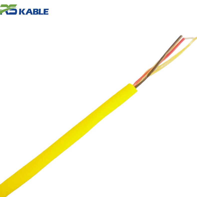
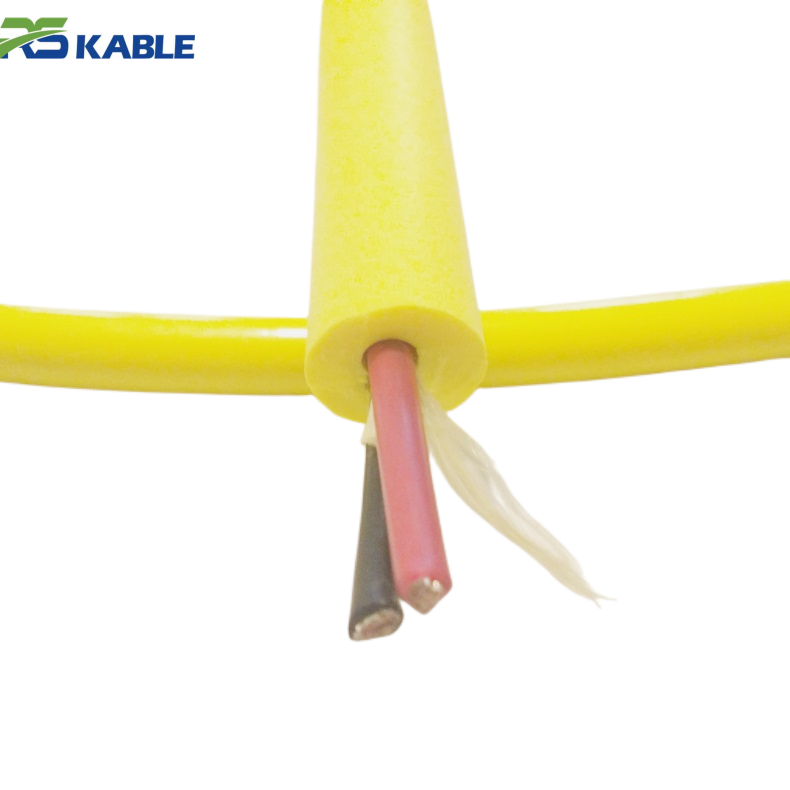
High-Flex Twisted Copper Conductor PVC ROV Cable | Flexible Subsea Robotic Power & Signal Cable
Specifically engineered for **industrial robots and subsea robotic systems**, this **high-flex ROV cable** features **finely stranded twisted copper conductors** and a durable PVC jacket. It offers exceptional flexibility for dynamic applications, ensuring reliable power and signal transmission during continuous multi-axis movements in both industrial and underwater environments.
Failure Mode 1 — Jacket wear that becomes a bigger problem later
What crews usually notice
-
shiny scuff bands
-
repeated abrasion marks in a consistent zone
-
small cuts that look cosmetic
-
jacket thinning at one location
What usually causes it
-
seabed drag from excess slack or low catenary
-
current sweep into structure or debris
-
pinch points on deck routing
-
fairlead/sheave edge contact
-
repeated rubbing in the same drum layer
“Stop / Monitor / Continue” rule
-
Stop if reinforcement is visible or the cut is deep enough to form a path for water ingress.
-
Monitor if it’s superficial scuffing but growing job-to-job in the same zone.
-
Continue only when wear is stable and a protection plan exists (sleeve/route change).
Preventive actions that actually reduce wear
-
mark and photograph wear zones after each shift (patterns matter)
-
install protective sleeves at known contact points
-
adjust payout discipline to reduce bottom loops
-
eliminate sharp-edge routing points on deck (this is a top hidden cause)
Failure Mode 2 — Local crush damage and hard spots (the “silent killer”)
What it looks like
-
a stiff segment that won’t lay smoothly
-
flattening or a “pressed” feel
-
a kink history after a hurried recovery
-
cable piles unevenly on the drum
Common triggers in real operations
-
over-tight spooling tension on a drum
-
tight bend over undersized sheaves
-
cable trapped under equipment or crossed under load
-
sudden angle changes at routing points during recovery
Why it matters
Crush damage often creates internal deformation that:
-
accelerates conductor fatigue
-
creates micro-pathways for water ingress
-
increases optical loss risk in fiber systems
-
becomes a future failure point even if it “works today”
Practical response
-
Tag the location immediately (distance marker or drum wrap reference)
-
Do not keep cycling that zone until it’s evaluated
-
If hard spot repeats or grows, remove from service or cut back and re-terminate if feasible
Failure Mode 3 — Water ingress and insulation breakdown
What it looks like operationally
-
faults appear after wet recovery or cleaning
-
insulation readings trend downward over time
-
power behavior becomes unstable under load
-
corrosion signs near interfaces
Typical causes
-
jacket cuts that were ignored
-
seal degradation at a termination boundary
-
contamination that compromises sealing surfaces
-
damage that happened on deck and only shows after pressure exposure
Prevention that works
-
treat new jacket cuts as urgent (not cosmetic)
-
rinse and dry connectors properly; prevent salt crystal buildup
-
keep caps on whenever unmated
-
store baseline insulation checks so you can spot trends early
Failure Mode 4 — Conductor fatigue (intermittent opens)
The classic symptom
Everything is fine until the ROV moves, turns, or hits a certain tether angle—then power flickers or resets.
Where it happens most often
-
within the first meters behind a termination
-
at a fixed routing point where the same bend repeats
-
at a location where bend radius is violated daily
What usually causes it
-
bending concentrated at one point (poor strain relief or routing)
-
repeated tight bends during storage/handling
-
cumulative cycles from long shifts and frequent redeployment
Prevention
-
ensure the termination has a real “flex zone,” not a sharp stiffness transition
-
change routing so the bend point is distributed, not fixed
-
enforce minimum bend radius during deck operations
Movement-only power faults are high-value early signals. Ignoring them often leads to complete loss later.
Failure Mode 5 — Fiber degradation and micro-bending loss
What crews see
-
video dropouts during movement only
-
increasing insertion loss compared to baseline
-
unstable telemetry correlated with bending
Common triggers
-
bending below safe radius near connectors
-
crush damage in drum layers
-
strain relief that concentrates stress
-
tight reeling under high tension
Prevention
-
establish a fiber baseline before deployment and compare after major events
-
treat kink/hard spot events as “fiber risk” until proven otherwise
-
protect routing points where fiber stress concentrates
Failure Mode 6 — Termination and connector issues (the highest-frequency downtime source)
What it looks like
-
faults clustered near the end of the tether
-
contact contamination or corrosion signs
-
cracked overmold or damaged strain relief
-
intermittent issues after mate/unmate cycles
Why it happens
Terminations combine three stressors:
-
sealing boundary
-
load transfer
-
repeated bending
Prevention habits that reduce connector downtime
-
always cap when unmated (no exceptions)
-
rinse, dry, and store properly after each use
-
inspect overmold/strain relief for micro-cracks early
-
avoid bending right at the connector exit during handling
Connectors don’t fail because they are “weak.” They fail because they are the most stressed and most handled parts of the system.
Symptom-to-Root-Cause Table (fast diagnosis)
-
Video drops only during turns → fiber micro-bending, bend radius violation, termination fatigue
-
Power resets under heavy thrust → voltage drop, termination heating, insulation weakness
-
Fault appears after recovery → handling damage, water ingress pathway, connector contamination
-
Tether feels sticky near structure → seabed/structure contact friction, slack loop holding point
-
New hard spot found during payout → crush or kink event; treat as a high-risk zone
This keeps troubleshooting focused and prevents “replace everything” guesswork.
Preventive maintenance schedule (field-friendly)
Every deployment (fast checks that take minutes)
-
inspect first 10–20 m visually (highest handling damage zone)
-
check connector caps, cleanliness, and contact condition
-
inspect strain relief and overmold for cracks or sharp stiffness transitions
-
verify routing has no pinch points and respects bend radius
-
log any new wear location with a simple reference (drum wrap or meter mark)
Every week (pattern discovery)
-
full-length inspection during controlled spooling
-
locate and confirm repeated wear bands
-
feel-check for hard spots during payout
-
run basic electrical continuity/insulation checks suitable for your system
-
compare fiber insertion loss to baseline if fiber is in the tether
Every month (prevent downtime, not just document it)
-
termination-focused inspection and cleaning review
-
evaluate whether wear zones require routing changes or protection sleeves
-
assess whether seabed drag indicates payout/buoyancy mismatch
-
decide on re-termination, cut-back, or retirement for recurring defect zones
The value of the schedule is not the paperwork—it’s turning random failures into predictable maintenance.
After-incident procedure (what to do after a snag, hard recovery, or kink)
Treat these events as maintenance triggers:
-
identify and mark the suspected zone immediately
-
inspect for jacket cuts, crushing, and stiffness change
-
compare electrical readings to baseline (if available)
-
compare fiber loss to baseline if fiber exists
-
decide: protect and monitor, cut-back and re-terminate, or retire
The most expensive mistake is returning to work without checking the damage zone.
Replace vs re-terminate vs keep working (a practical decision rule)
Keep working (with monitoring) if:
-
scuffs are superficial and stable
-
no hard spot or crush is present
-
no trending insulation decline is observed
-
performance is stable under movement
Re-terminate (or cut-back) if:
-
faults correlate with movement near the termination
-
strain relief or overmold damage is visible
-
connector-side faults repeat despite cleaning and proper storage
-
a defect zone can be removed without compromising length requirements
Retire/replace if:
-
repeated hard spots or crush zones appear
-
insulation trends downward and does not stabilize
-
optical loss continues to rise despite termination service
-
reinforcement is exposed or damage is extensive
This reduces debate during a busy shift and makes decisions consistent.
FAQ
What is the most common ROV tether failure point?
Terminations and strain relief zones. They combine sealing, load transfer, and repeated bending stress.
Why does video fail only when the ROV moves?
That pattern usually indicates bending stress—fiber micro-bending, bend radius violations, or termination fatigue.
What does a “hard spot” mean on a tether?
It often indicates crush damage or internal deformation. It should be tagged and evaluated before continued cycling.
How can I reduce seabed drag wear?
Control slack, manage payout discipline, improve catenary behavior, and protect known contact zones with sleeves or routing changes.
When should I re-terminate instead of replacing the whole tether?
When the defect is localized near the termination or a small section can be cut back without sacrificing required working length.