ROV Cable Customization Guide: Core Count, Fiber Options, and Strength Member Choices
ROV cable customization starts where catalog selection ends. Standard tethers cover the middle of the application envelope — a known depth, a typical load, a conventional sensor mix. Move outside that envelope and you are specifying a custom cable. The question is whether you know how to specify it correctly.
This guide is written from the inside of the design process. It explains how each major customization decision is made, what information the engineer needs to make it well, and where the constraints lie. By the end of this article, you will know what questions to ask, what data to prepare, and what trade-offs to expect when you request a custom ROV cable.
The decisions are organized as a specification sequence — the order in which they should be resolved, because each decision constrains the next.
“The most expensive custom cable mistakes happen before the first drawing is made. Someone tells us the core count, but not what each core is for. We build it, and they discover on the first dive that they needed a coaxial conductor where we put a twisted pair. A complete application brief at the start saves three months of re-specification.”
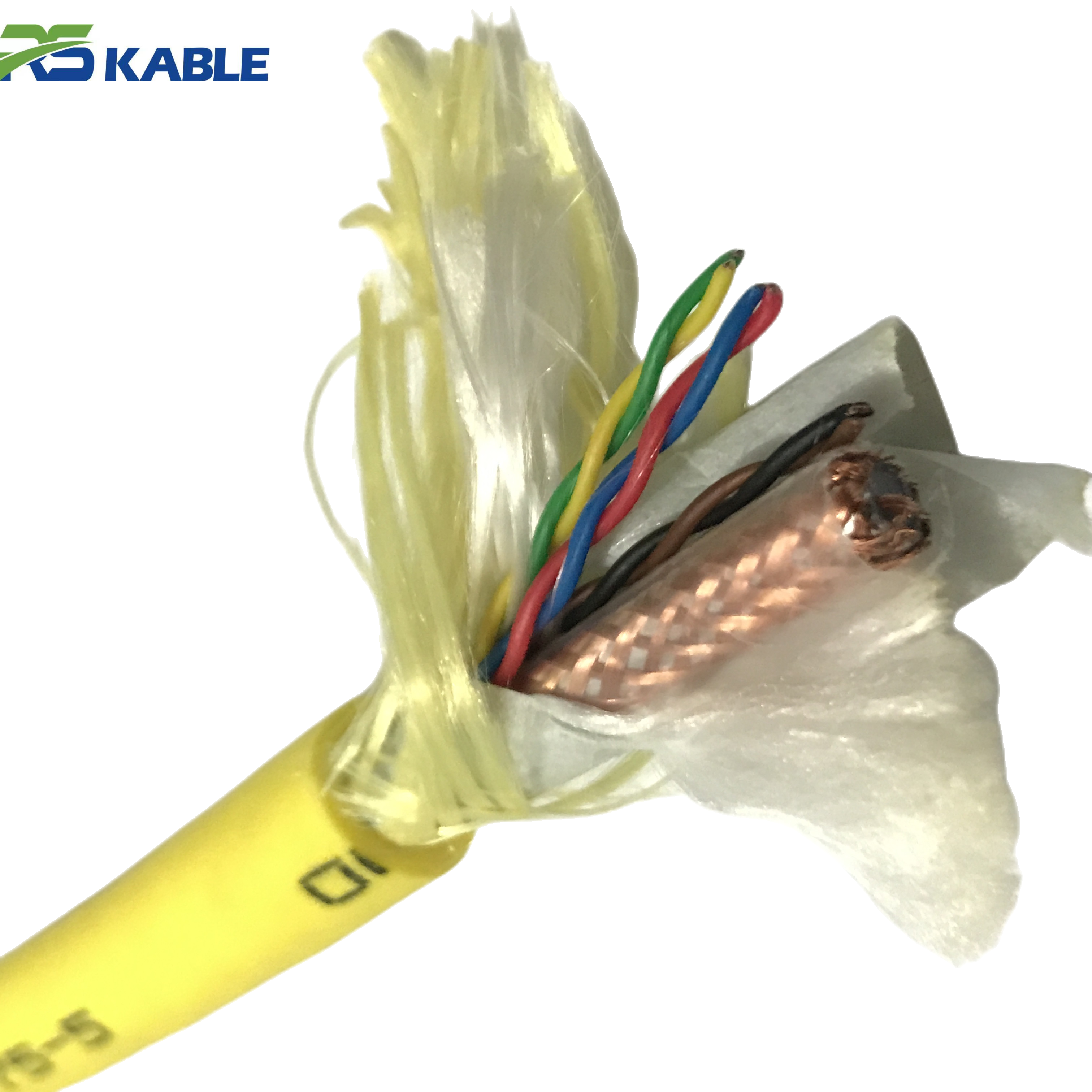
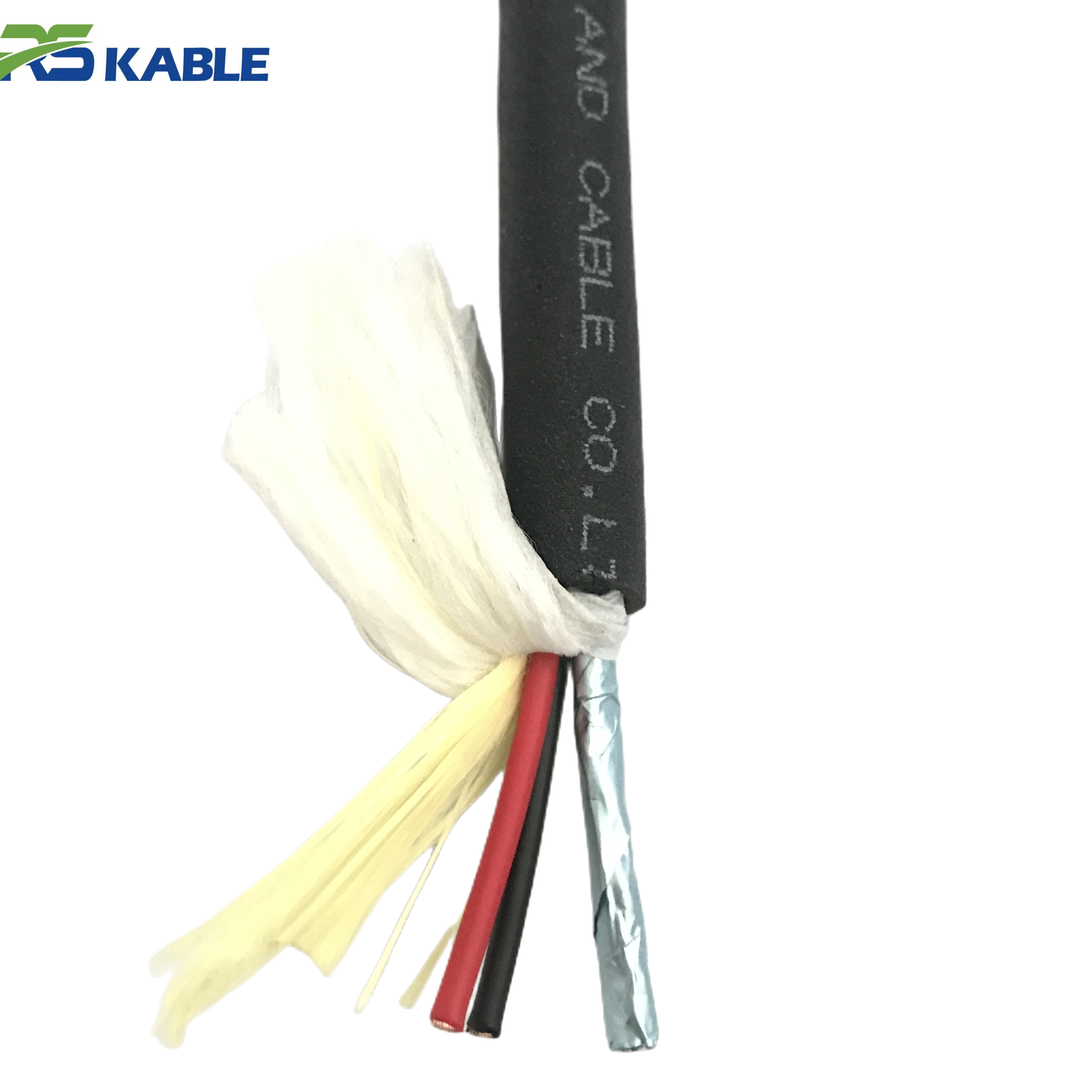
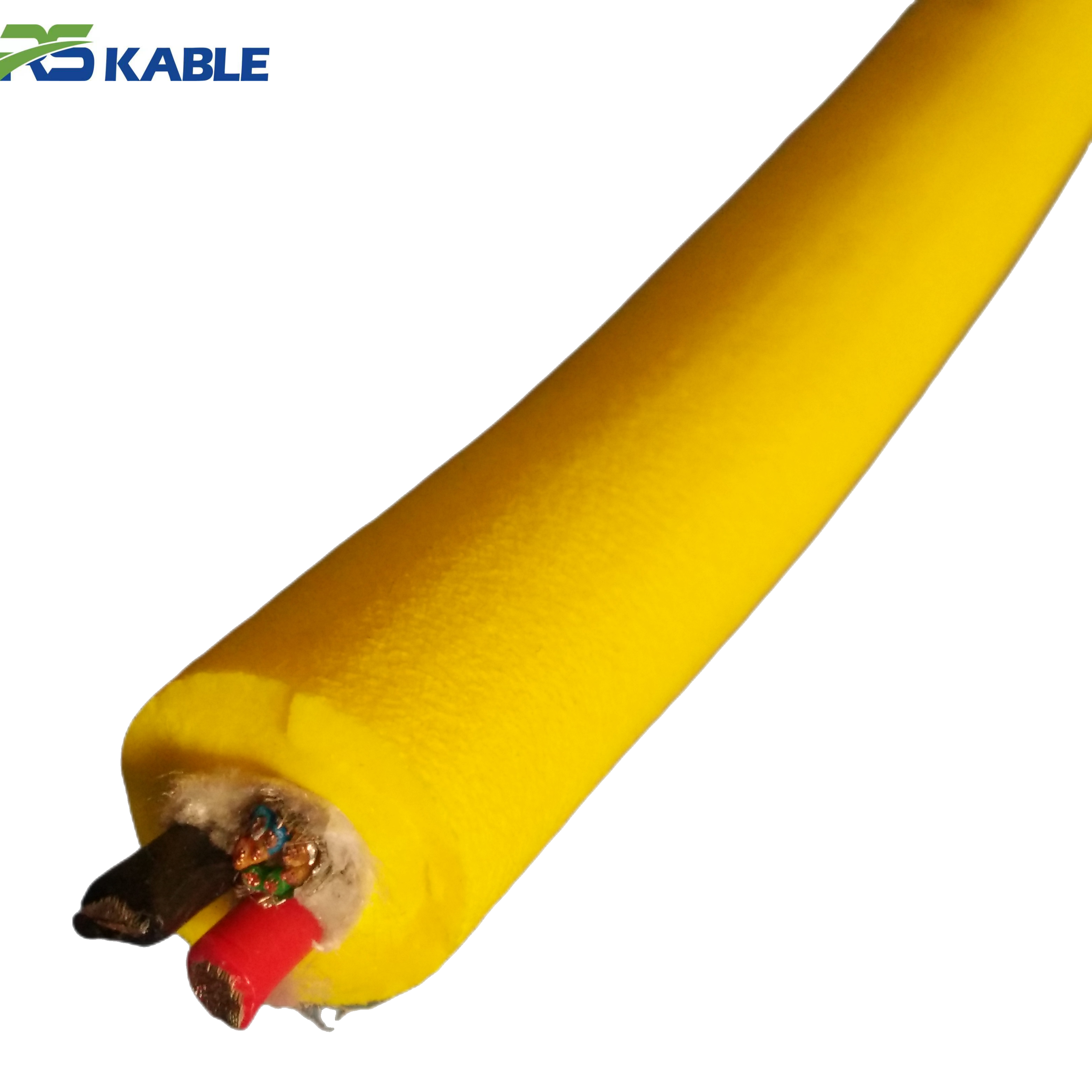
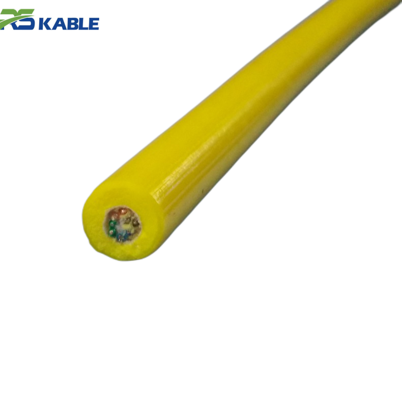
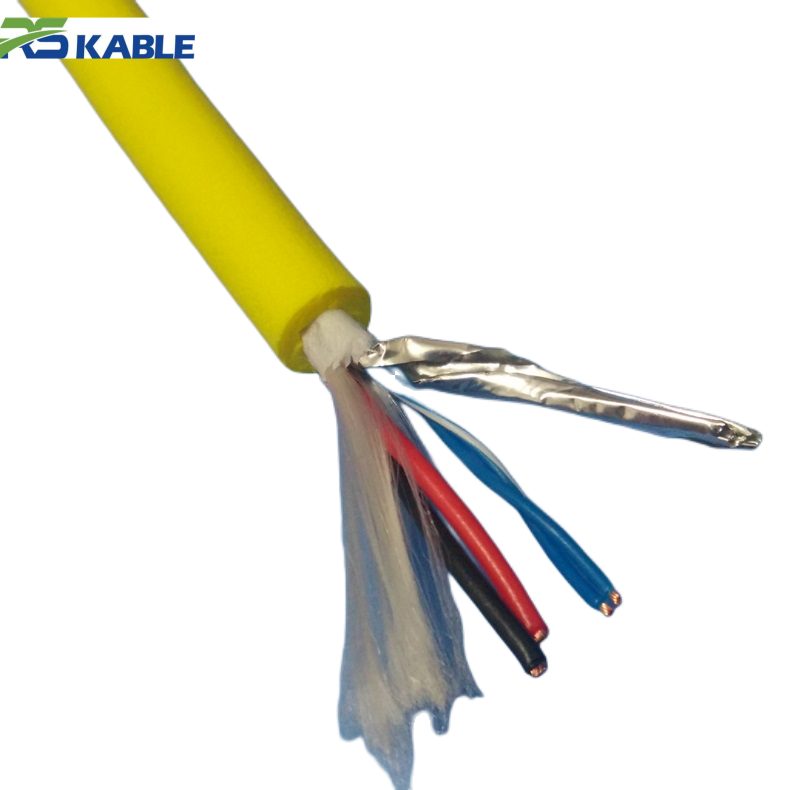
Custom 2/3/4-Core Fiber Optic Power Cable ROV – Zero Buoyancy Composite Cable for Underwater Drone Cameras
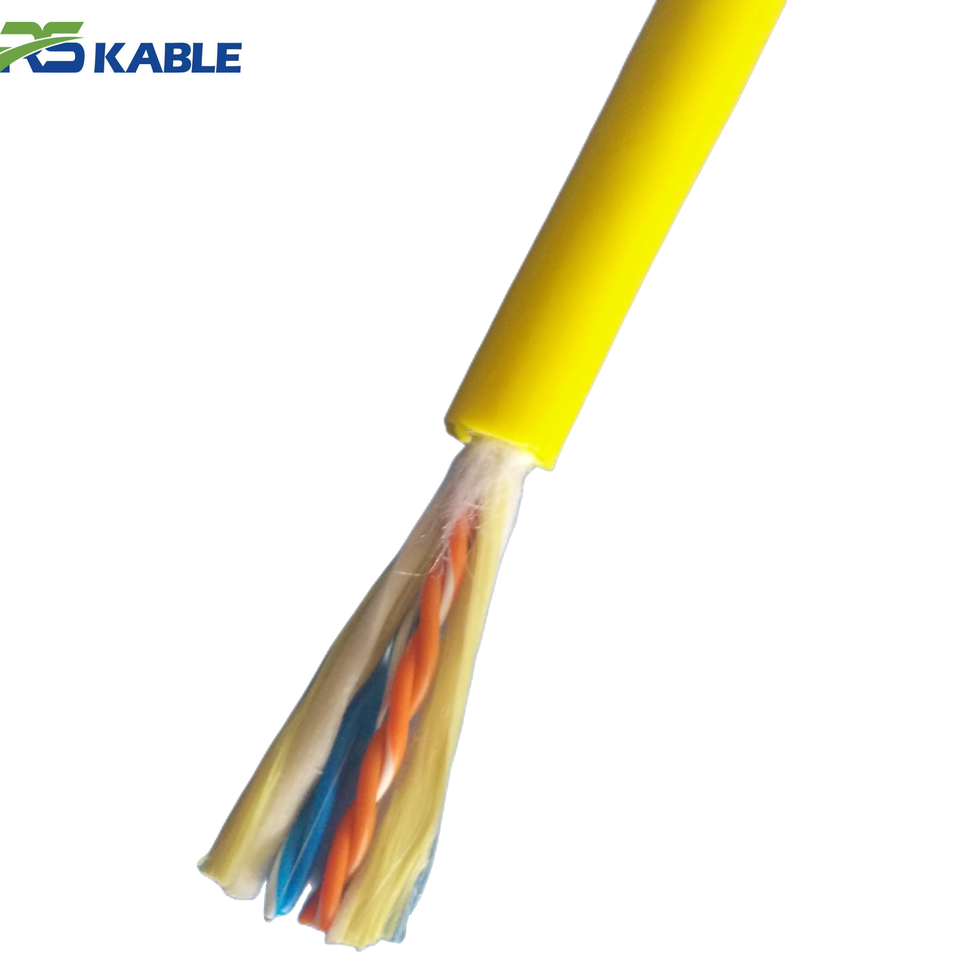
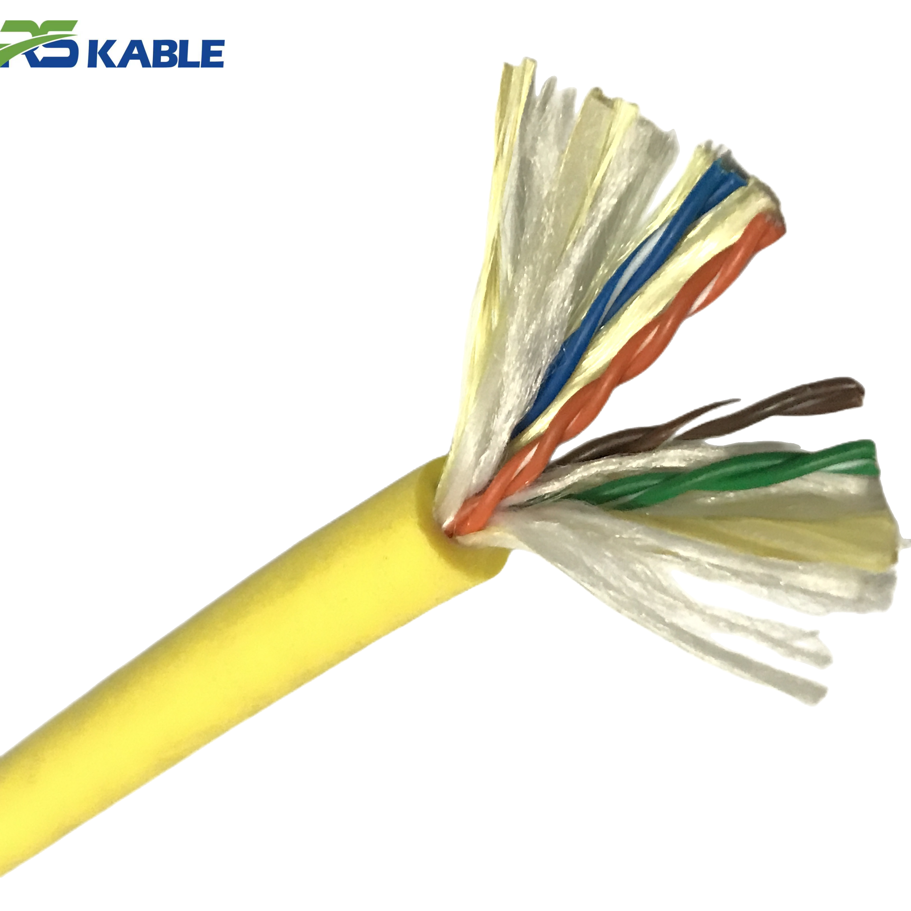
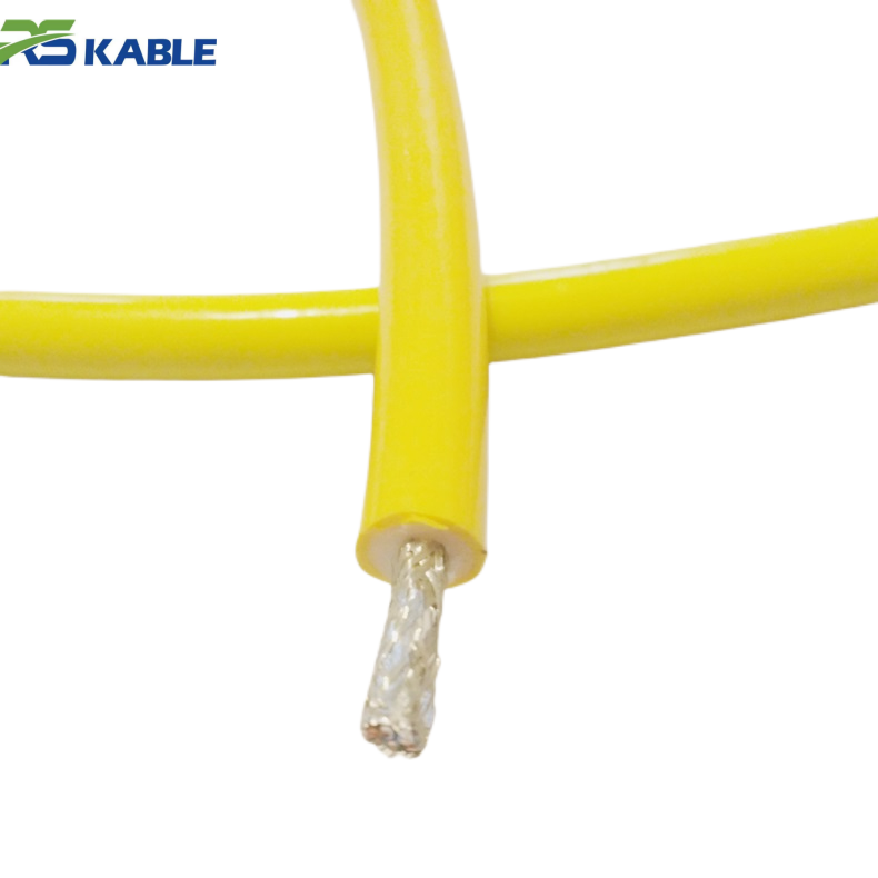
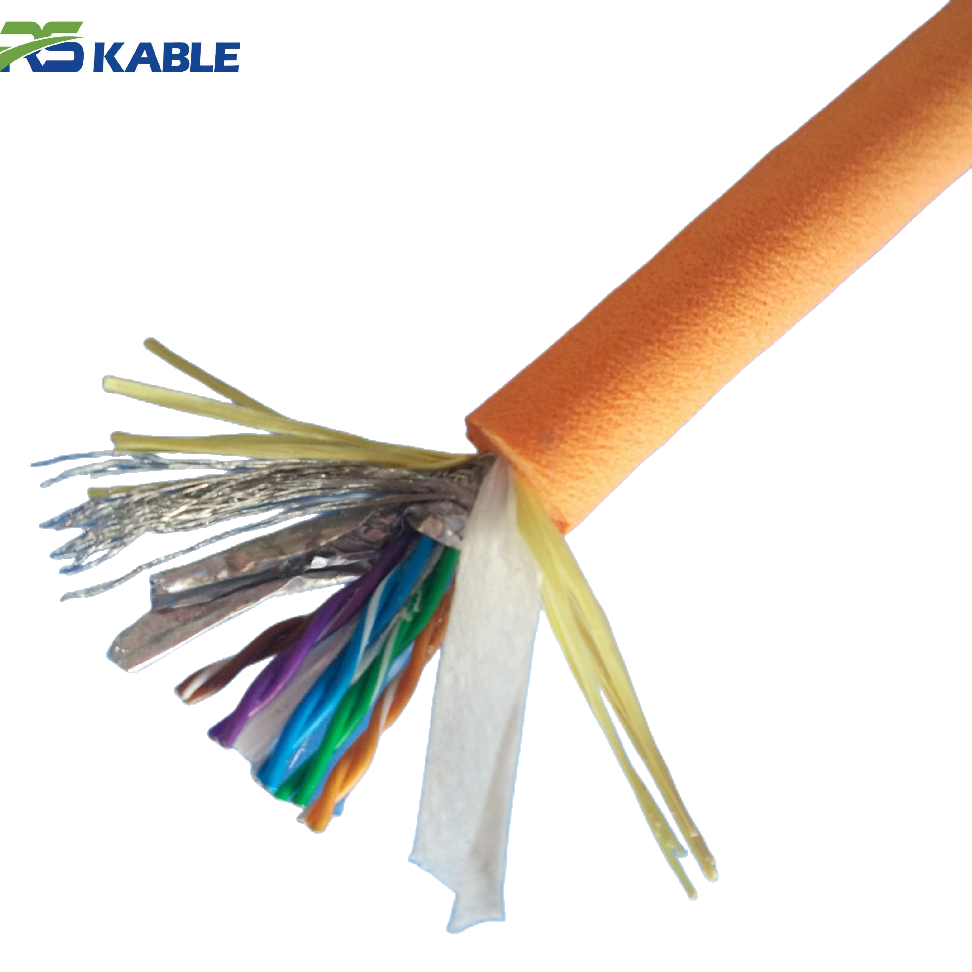
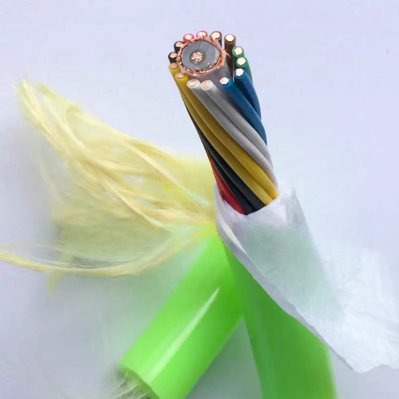
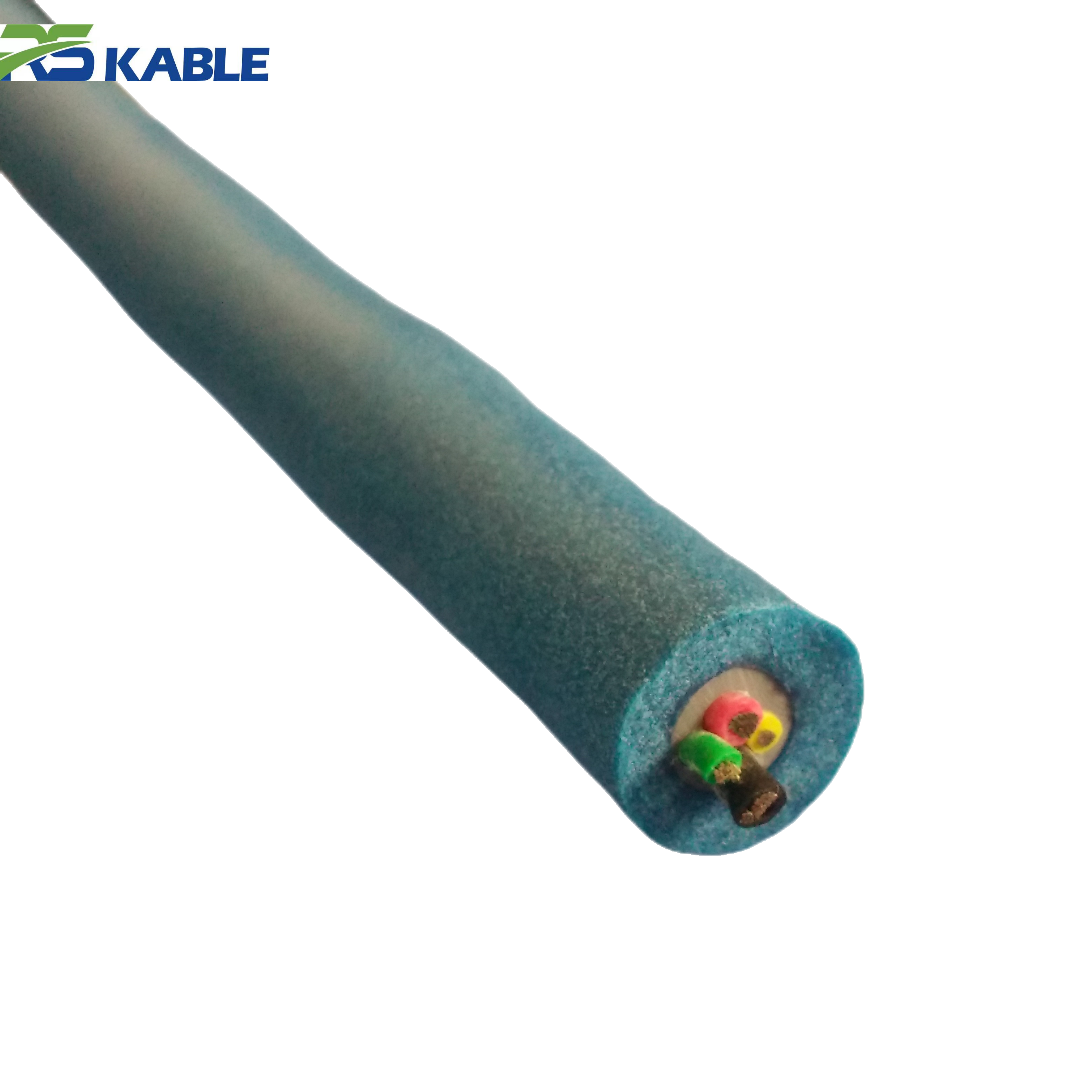
This customizable ROV composite cable integrates power conductors and fiber-optic communication in a single zero-buoyancy tether. Designed for underwater drones and inspection cameras, it provides stable power supply and high-speed data transmission while maintaining neutral buoyancy to reduce drag and improve maneuverability during subsea operations. Fiber count, core configuration, and tensile reinforcement options can be customized for different ROV deployment requirements.
1. Before Any Specification: The Application Brief
Every successful custom cable begins with an application brief. This is a document the customer provides — not a form the manufacturer fills in. It describes what the cable must do, not what it must be. The manufacturer’s design engineers translate the functional requirements into a physical specification.
An incomplete brief produces an incomplete specification. A brief that describes the cable in terms of physical parameters rather than functional requirements produces a cable that meets those parameters but may not meet the actual need.
What a complete application brief contains
|
Brief category |
Information required |
|
Vehicle and mission |
ROV class (observation / work-class / scientific), operating depth range, mission type (survey / inspection / intervention / research) |
|
Power requirements |
Peak load current and voltage at vehicle terminals, supply voltage at surface, acceptable voltage drop at peak load |
|
Signal and data |
Number of signal circuits, data type per circuit (Ethernet / RS-485 / analog video / sonar / serial), bandwidth requirement per circuit, acceptable BER or SNR floor |
|
Mechanical environment |
Deployment method (drum / hand-deployed / A-frame), minimum bend radius in operation, expected number of deployment cycles per year, any crush or abrasion hazard |
|
Buoyancy requirement |
Neutral / negative / positive buoyancy required, operating salinity and temperature (affects seawater density and therefore neutral buoyancy point) |
|
Environmental exposure |
UV exposure (tropical / northern latitude / covered storage), chemical exposure (hydraulic fluid / fuel / seawater / freshwater only), operating temperature range |
|
Compliance requirements |
Any certification requirements (DNV / Lloyd’s / IMCA / MIL-spec), applicable electrical standards (IEC 60228 / IEC 62368-1), client specification documents if applicable |
Table 1. Application brief content checklist. Provide all categories before requesting a cable specification. Missing information in any category will extend the design process and may require design revision after prototyping.
Design principle: A custom cable specification is only as good as the application brief behind it. Physical parameters — conductor size, insulation type, armor material — are outputs of the design process, not inputs to it. The inputs are functional: what power, what signals, what mechanical environment, what depth.
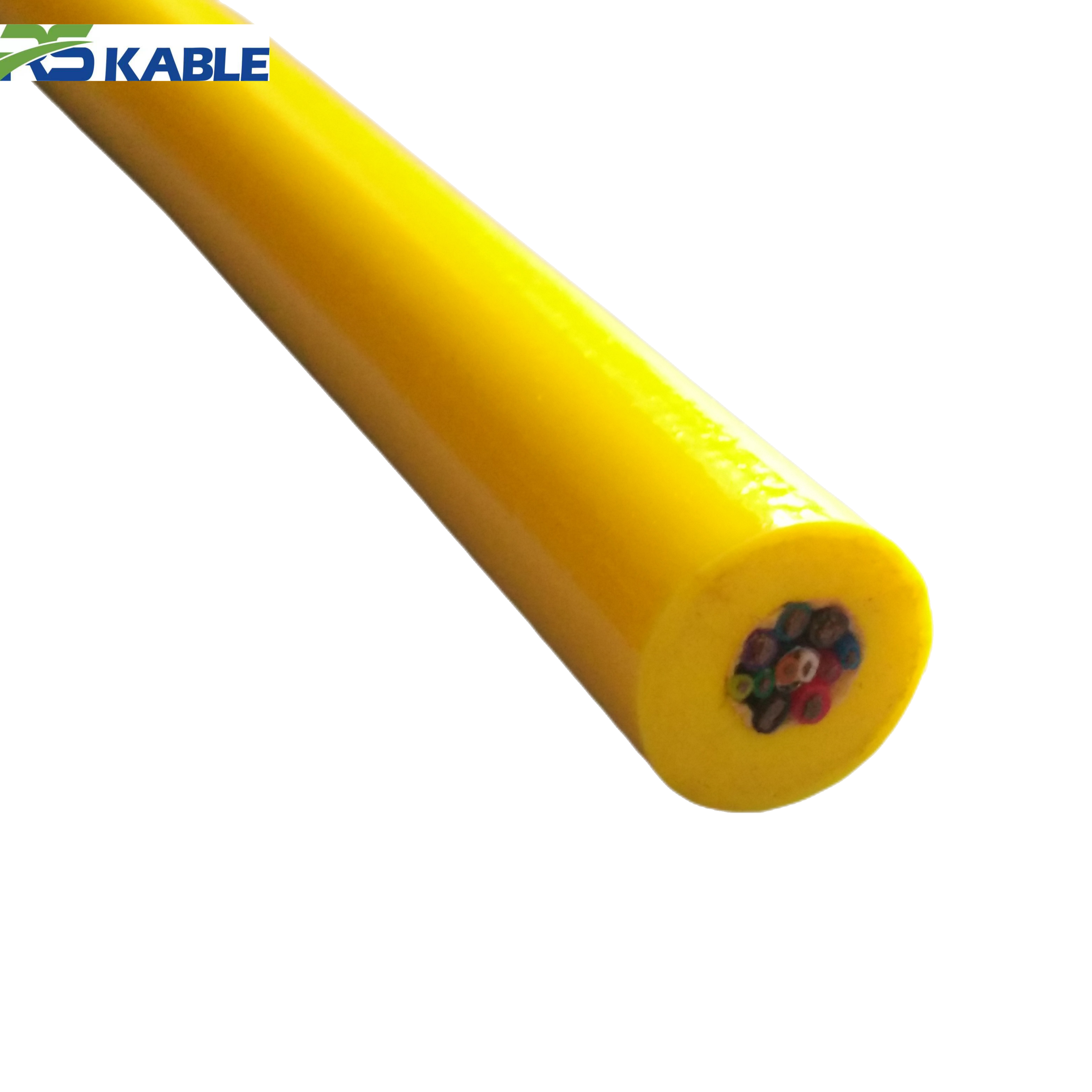
2. Core Count: Fewer Is Almost Always Better
Core count is the first structural decision in ROV cable customization. Every additional core adds weight, increases diameter, reduces flexibility, and raises cost. The design goal is the minimum core count that satisfies all functional requirements — not the maximum that might prove useful one day.
How to count cores correctly
A “core” in cable terminology is a single insulated conductor. A twisted pair is two cores. A coaxial conductor is one core plus its shield (which is treated as a separate conductor in the cable cross-section). A fiber optic element is counted separately — it is not a “core” in the electrical sense but occupies space in the cable and must be accounted for in the cross-section design.
To determine the correct core count, list every electrical circuit the cable must carry. For each circuit, identify the conductor type, the required cross-sectional area, and whether it shares a common reference (ground) with other circuits. Then consolidate: circuits sharing a common ground may share a single return conductor if their current levels allow it.
The consolidation trade-off
Consolidating return conductors reduces core count but creates a shared ground path. Any noise current on one circuit shares the return path with all other consolidated circuits. For circuits that mix power and signal — a common situation in ROV tethers — consolidation introduces ground-coupled noise from the power return into the signal circuits.
The standard engineering practice is to keep power return conductors separate from signal return conductors, even if both are referenced to the same system ground. This adds two cores — one power positive, one power return — but isolates the noisier power circuit from the sensitive signal circuits. The cost in cable diameter and weight is almost always justified by the reduction in signal interference.
Spare cores: the maintenance argument
Most custom ROV cable specifications include one or two spare cores. Spare cores allow a failed conductor to be bypassed at the vehicle interface without replacing the cable. A cable with no spares must be replaced or repaired the moment any conductor develops an irreparable fault mid-operation.
The counterargument is that spare cores add weight and diameter for a capability that may never be used. For short-range, frequently replaced observation-class tethers, spares are often omitted. For long tethers on work-class vehicles where replacement involves significant logistics and cost, the weight penalty of two spare cores is invariably worth the operational insurance they provide.
3. Conductor Type and Cross-Section
Copper conductor stranding class
All power and signal conductors in ROV tethers use stranded copper — the question is which stranding class. IEC 60228 defines five stranding classes for flexible cables. Classes 5 and 6 are the relevant ones for dynamic ROV applications:
|
IEC Class |
Wire diameter |
Flexibility |
Best application |
|
Class 5 |
Medium fine |
Good — standard flex |
Observation-class tether, moderate cycle count |
|
Class 6 |
Fine / ultrafine |
Excellent — high cycle |
Work-class tether, high cycle count, tight bend radius |
|
Bunched / rope-lay |
Very fine bunched |
Maximum flexibility |
Ultra-flexible drag chain style — rarely used in tethers |
Table 2. Copper conductor stranding classes for ROV tether applications. Class 6 has more, finer wires than Class 5 — this distributes bending stress across more strands and extends fatigue life at tight bend radii.
Cross-section sizing for power conductors
Power conductor cross-section is determined by two constraints: the current-carrying capacity (to avoid overheating under rated load) and the voltage drop (to ensure adequate voltage at the vehicle terminals). In ROV tether design, the voltage drop constraint almost always dominates — the current required to cause thermal overheating on a conductor immersed in seawater is far higher than the current that produces unacceptable voltage drop over the tether length.
The correct procedure is to calculate the required cross-section from the voltage drop constraint first. Then verify the resulting conductor can carry the peak current without exceeding its temperature rating. If both constraints are satisfied, the smaller cross-section that passes both tests is the correct specification.
Signal conductor impedance matching
Digital signal conductors — Ethernet, RS-485, CAN bus — require controlled impedance. The characteristic impedance of a twisted pair depends on the conductor diameter, the insulation thickness and dielectric constant, and the twist pitch. For Ethernet (100BASE-TX), the target impedance is 100Ω ±15%. For RS-485, it is 120Ω.
Custom cable manufacturers can produce twisted pairs to a specified impedance, but the tolerance requires careful process control. Request impedance test data as part of the cable acceptance documentation. A conductor pair that measures 85Ω or 140Ω in a 100Ω specification will produce reflections and bit errors at high data rates over long cable runs.
4. Fiber Optic Options: A Decision Framework
Fiber optic elements are the most consequential customization decision in a modern ROV tether. They determine the bandwidth ceiling of the entire system. They also introduce the most fragile component in the cable cross-section — a constraint that affects every other design parameter.
Single-mode vs multimode: the definitive comparison
|
Property |
Single-mode (OS2, 9/125 μm) |
Multimode (OM3/OM4, 50/125 μm) |
|
Bandwidth |
Effectively unlimited for practical tether lengths |
Up to 10 Gbps at ≤300 m; 1 Gbps at ≤2 km |
|
Transmission distance |
Single transceiver: up to 80 km |
Practical limit: 300 m for 10G, 2 km for 1G |
|
Light source required |
Laser (VCSEL or DFB) — more expensive |
LED or VCSEL — lower cost |
|
Connector alignment tolerance |
Tight — small core requires precision alignment |
More forgiving — larger core easier to align |
|
Bend sensitivity |
Higher — tighter bend radius specification |
Lower — more tolerant of bending |
|
Cost (cable element) |
Slightly higher |
Slightly lower |
|
Recommended for |
Work-class ROV > 200 m, scientific ROV, HV tether with fiber |
Observation-class ROV < 200 m, budget-constrained programs |
Table 3. Single-mode vs multimode fiber comparison for ROV tether applications. For any new tether specification with fiber, single-mode is the preferred choice unless cost or transceiver availability is a binding constraint.
Buffer type: tight-buffered vs loose-tube
The mechanical protection around the optical fiber in a dynamic tether determines the fiber’s long-term reliability.
- Tight-buffered fiber: The fiber is directly coated with a 900 μm polymer buffer. This makes it robust against handling and bending. Tight-buffered fiber is the correct choice for dynamic ROV tethers where the cable undergoes repeated bending during deployment and recovery cycles.
- Loose-tube fiber: The fiber floats in a gel-filled tube. This protects against longitudinal tension — the gel allows the fiber to move relative to the tube under cable stretching. Loose-tube is preferred for static installations and long-distance submarine cable where thermal expansion and cable tension are the primary concerns, not dynamic bending. It is not appropriate for dynamic ROV tether applications.
Fiber count: how many fibers to specify
A minimum of two fibers should be specified for any ROV tether carrying fiber — one active, one spare. The cost increment of a second fiber in a cable is negligible. The operational cost of a tether with a single failed fiber and no spare is a full cable replacement.
For systems requiring full duplex optical communication, two fibers are required for a single channel (one fiber per direction). A tether carrying two independent data channels requires four fibers minimum. High-specification scientific ROV tethers often carry 6–12 fibers to support multiple independent instruments, future expansion, and redundancy.
Fiber minimum bend radius in the cable design
The fiber’s minimum bend radius must be incorporated into the cable’s structural design — not treated as a separate constraint to be managed operationally. Tight-buffered single-mode fiber typically has a long-term minimum bend radius of 30 mm. The cable’s cross-section geometry and armor structure must ensure that no fiber element is subjected to a bend radius smaller than this specification at the cable’s minimum operational bend radius.
This requirement directly constrains the cable’s minimum operational bend radius. A cable with tight-buffered fiber cannot have a minimum bend radius smaller than the fiber’s minimum bend radius plus a mechanical margin factor. This constraint often increases the cable’s minimum bend radius compared to an equivalent cable without fiber — which affects drum diameter specification and fairlead design.
Specification note: Request optical attenuation data as part of the fiber acceptance test. Maximum attenuation for OS2 single-mode fiber is 0.4 dB/km at 1310 nm and 0.3 dB/km at 1550 nm per IEC 60793-2-50. Any tether that exceeds these values has either defective fiber or a mechanical damage event during manufacture. Reject it and request investigation before acceptance.
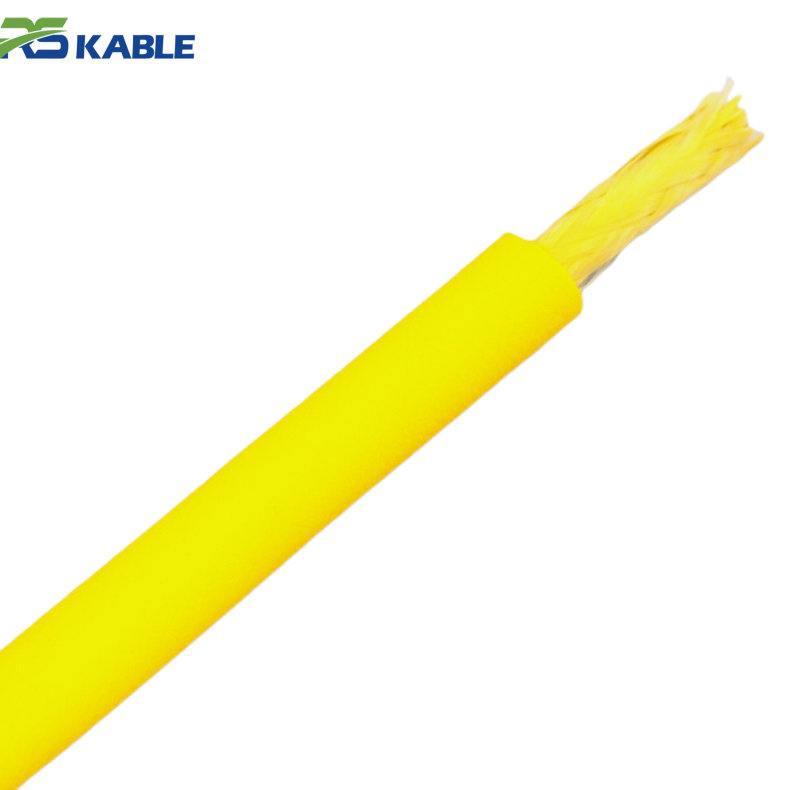
5. Strength Member Choices
The strength member carries the tensile load in the cable. It is the structural backbone that prevents the cable from stretching or parting under deployment tension. The choice of strength member material is one of the most consequential decisions in ROV cable customization — it determines the cable’s tensile capacity, weight, stiffness, and cost simultaneously.
The five strength member materials
|
Material |
Tensile strength |
Weight |
Stiffness |
Best application |
|
Galvanized steel |
1,500–2,000 MPa |
High |
Very high |
Cost-sensitive static or low-dynamic tethers; short service life in seawater |
|
316L stainless steel |
1,400–1,800 MPa |
High |
Very high |
Marine environment; longer service life; standard for armored ROV tether |
|
Kevlar (aramid) |
2,800–3,600 MPa |
Very low |
Medium |
Weight-critical tethers; neutral buoyancy designs; does not corrode |
|
Vectran (LCP) |
2,800–3,200 MPa |
Very low |
Low creep |
Deep scientific tether; superior creep resistance vs Kevlar; higher cost |
|
HMPE (Dyneema) |
2,400–3,500 MPa |
Near-zero |
Low (creep risk) |
Ultra-light tether; caution on sustained tension — creep under load |
Table 4. Strength member material comparison. Specific strength (MPa per unit density) favors aramid fiber over steel by approximately 5:1, but steel retains its advantages in abrasion resistance, dimensional stability, and cost. The correct choice depends on which property is the binding constraint.
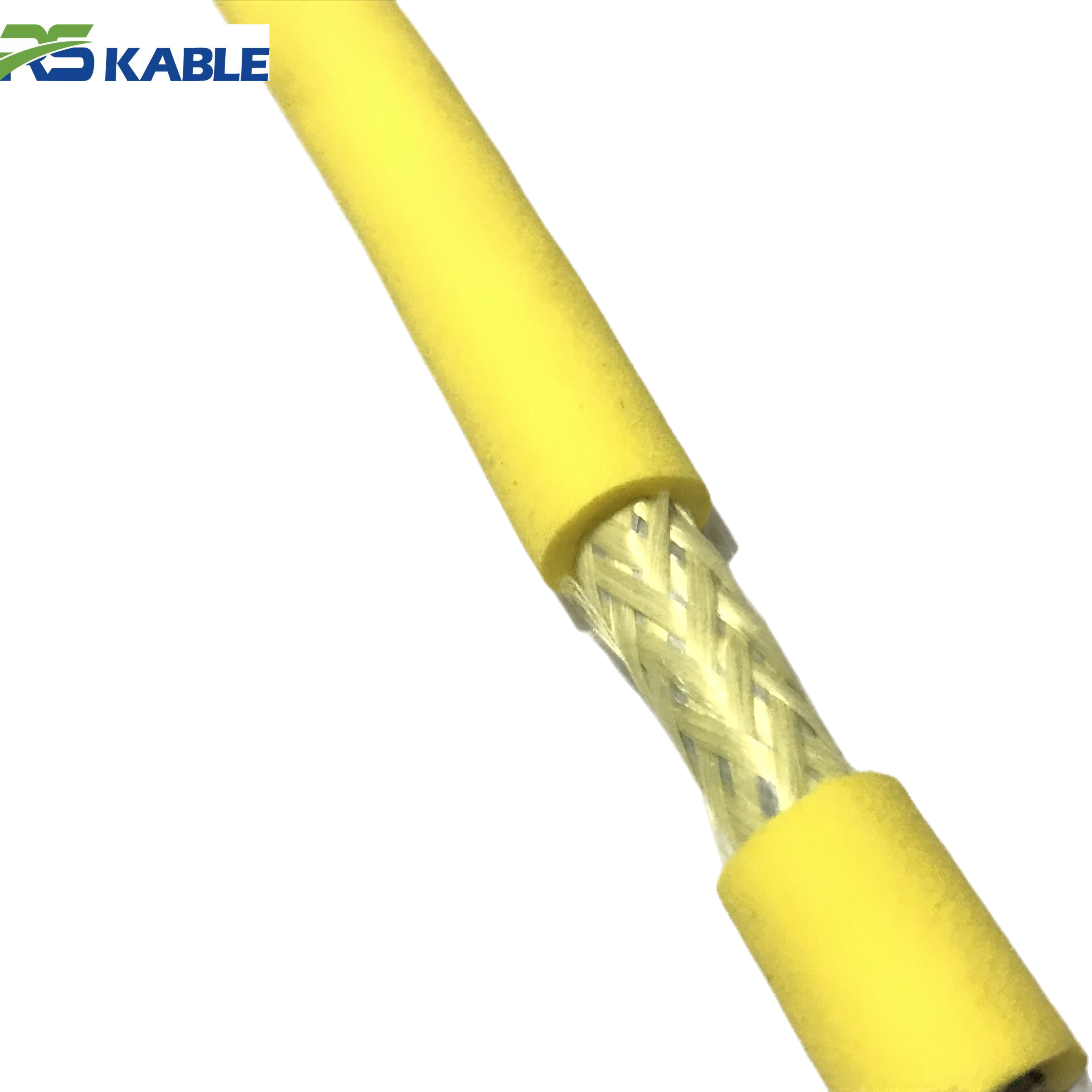
Single armor vs double armor construction
Single armor uses one helical layer of strength member wires. Double armor uses two counter-wound layers. The structural implications are significant beyond the obvious doubling of crush and abrasion protection:
- Torque balance. A single armor layer under tension develops a torsional moment — the helical wires try to unwind. This torques the cable and any device attached to its end. Double armor, with counter-wound layers, cancels this torsional moment. For any application where tether rotation affects vehicle heading or sensor orientation, double armor is required.
- Tensile capacity. Double armor roughly doubles the cross-sectional area of strength member material, which proportionally increases tensile capacity. For high-load applications — work-class ROV deployment, long-range towing — this additional capacity provides a meaningful safety factor increase.
- Weight and flexibility. Double armor adds weight and reduces flexibility. For observation-class tethers where the vehicle weight is modest and the deployment system is hand-operated, double armor is usually over-specified.
Calculating the required safety factor
The working tensile load on a tether includes: the submerged weight of the deployed tether, the drag force from the current acting on the cable, and the vehicle’s maximum thrust in the vertical direction. The safety factor is the ratio of the breaking strength to the maximum working load.
IMCA guidelines for ROV tether safety factor recommend a minimum of 3:1 for observation-class vehicles and 5:1 for work-class. Certification society requirements (DNV, Lloyd’s) typically require 4:1 minimum with independent verification. The appropriate safety factor for a custom tether should be specified in the application brief — it directly determines the required strength member cross-section and therefore the cable’s weight and diameter.
“Customers often ask for the minimum cable that will hold the vehicle. That is the wrong question. The right question is: what is the minimum cable that will hold the vehicle for five years of intensive use, including the load cases that happen once in a hundred dives? Those are very different cables.”
6. Jacket and Insulation Material Selection
Choosing the outer jacket compound
The outer jacket is the first line of defense against the cable’s mechanical and chemical environment. The most common material choices are:
|
Material |
Abrasion resist. |
Chemical resist. |
Notes |
|
PUR (polyurethane) |
Excellent |
Good — most hydrocarbons |
Standard choice for offshore ROV tethers. Flexible at low temperature. UV-stabilized grades available. |
|
PVC (polyvinyl chloride) |
Good |
Good |
Lower cost than PUR. Less flexible at low temperatures. Adequate for temperate-water, moderate-duty applications. |
|
TPE (thermoplastic elastomer) |
Good |
Moderate |
Softer feel; good flexibility at low temperature. Intermediate between PVC and PUR in cost and performance. |
|
HDPE (high-density polyethylene) |
Good |
Excellent — all chemicals |
Best chemical resistance. Stiffer than PUR. Preferred for deep-rated tethers where pressure resistance and chemical barrier performance matter. |
|
Silicone rubber |
Poor |
Excellent |
Use only where temperature range exceeds PUR capability (above 90°C or below −40°C). Not suitable for dynamic abrasion environments. |
Table 5. Outer jacket material comparison. PUR is the default for most ROV tether applications. Substitute HDPE for deep-rated or chemically aggressive deployments.
Conductor insulation
Conductor insulation is selected for dielectric strength, flexibility, and dimensional consistency. Polyethylene (PE) is the standard insulation material for ROV tether power conductors — its low dielectric constant minimizes capacitive coupling between conductors, and its dielectric strength is adequate for voltages up to 600 V with standard wall thicknesses.
For higher voltage conductors (above 600 V), cross-linked polyethylene (XLPE) provides improved dielectric strength and better temperature resistance. XLPE is specified for HV tether power conductors where the insulation wall must withstand both the operating voltage and the mechanical stress of repeated bending without developing micro-cracks that gradually reduce dielectric strength.
7. Putting It Together: A Customization Decision Framework
The following framework sequences the key ROV cable customization decisions in the order they should be resolved. Each row presents a condition. The “Yes” path and “No” path indicate the design direction.
|
Decision question |
If YES |
If NO |
|
Operating depth > 200 m? |
→ HV transmission — specify 150–600 VDC power conductors |
→ LV transmission adequate — 48 VDC power conductors |
|
Peak vehicle load > 1,000 W? |
→ Calculate conductor cross-section from voltage budget — likely 2.5 mm² or above |
→ 1.5 mm² conductors likely adequate — verify with voltage budget |
|
Data bandwidth > 100 Mbps? |
→ Fiber optic element required — specify single-mode OS2 tight-buffered |
→ Shielded twisted pair adequate for Ethernet or serial data |
|
Fiber included in design? |
→ Specify minimum 2 fibers — 1 active + 1 spare; tight-buffered; set cable MBR accordingly |
→ No fiber element — proceed to signal conductor specification |
|
Vehicle weight > 50 kg in air? |
→ Double-armor construction — torsional balance required for work-class operation |
→ Single-armor adequate — verify safety factor against IMCA guideline |
|
Safety factor requirement ≥ 5:1? |
→ Aramid or stainless steel armor — calculate cross-section for breaking strength |
→ Galvanized steel armor adequate for 3:1 minimum safety factor |
|
Neutral buoyancy required? |
→ Specify foam-filled or syntactic filler — calculate target submerged weight; aramid strength member preferred |
→ Standard filler acceptable — verify total cable weight-in-water |
|
Operating temperature below −10°C? |
→ PUR jacket, Class 6 conductors — specify low-temperature flexibility test |
→ Standard PUR or PVC jacket adequate for 0°C and above |
|
Chemical exposure to hydraulic fluid? |
→ PUR or HDPE jacket — specify immersion resistance test to ISO 6945 |
→ Standard jacket acceptable — UV stabilization only if outdoor storage |
|
Spare cores required? |
→ Add 2 spare conductors of the smallest active conductor size |
→ No spares — acceptable for short-range frequently replaced tethers |
Table 6. Customization decision framework — work through rows in sequence. Each answer constrains subsequent decisions. Use this table to prepare the specification brief before the first design consultation.
The specification builder: a reference template
After working through the decision framework, the completed specification for a custom tether should document the following parameters:
|
Parameter |
Options / range |
Trade-off to document |
|
Core count (power) |
1 pair (LV) / 1 pair per phase (HV) |
Additional cores = weight + diameter + cost |
|
Core count (signal) |
1–12 pairs depending on circuit count |
Consolidated returns save cores but risk noise coupling |
|
Spare cores |
0 / 2 / 4 |
Spares = insurance vs weight penalty |
|
Fiber count |
0 / 2 / 4 / 6 / 12 |
More fibers = redundancy + expansion vs marginal cost |
|
Fiber type |
OS2 single-mode / OM3 multimode |
Single-mode: better performance; multimode: lower transceiver cost |
|
Power conductor area |
0.75 / 1.5 / 2.5 / 4 / 6 mm² |
Larger area = less drop = heavier cable |
|
Conductor class |
IEC Class 5 / Class 6 |
Class 6 = longer fatigue life = marginally larger diameter |
|
Armor type |
Single / double galv. steel / SS316 / aramid |
See Section 5 — depends on tensile, weight, torque balance needs |
|
Jacket material |
PUR / PVC / HDPE / TPE / silicone |
See Section 6 — match to operating environment |
|
Buoyancy |
Negative / neutral / positive |
Neutral requires foam filler — increases OD |
|
Voltage rating |
300 V / 600 V / 1,000 V / custom HV |
Higher rating = thicker insulation = larger OD |
|
Safety factor (tensile) |
3:1 / 4:1 / 5:1 / custom |
Higher SF = stronger armor = more weight |
Table 7. Specification builder reference. Complete all rows before submitting a custom cable inquiry. Documenting the trade-off for each decision prevents post-design specification changes that delay manufacture.
8. The Specification Is the Product
Why the process matters as much as the outcome
A custom ROV cable can be manufactured to almost any combination of the parameters above. The engineering challenge is not manufacturing — it is resolving the interdependencies between parameters so the final design simultaneously satisfies every constraint.
Adding fiber increases the cable’s minimum bend radius. Increasing the bend radius may require a larger drum. Adding double armor increases weight. Increasing weight shifts the buoyancy calculation. Changing the buoyancy changes the foam filler volume. Changing the foam filler volume changes the outer diameter. Changing the outer diameter changes the drum capacity and the fairlead specification.
These interdependencies are why ROV cable customization requires iteration. A competent design engineer will trace the consequences of each decision through the full system and flag conflicts before manufacture begins. The application brief provides the constraints. The iteration produces the optimum.
What to expect from the design process
A realistic timeline for a custom ROV cable from initial application brief to first article prototype is 6–12 weeks for standard materials. Cables requiring non-standard strength members (Vectran, HMPE) or specialized jacket compounds extend this to 12–20 weeks due to material procurement lead times.
The design process should include: application brief review and clarification, first-pass specification with estimated outer diameter and weight, cross-section drawing for customer review, voltage budget and catenary model verification if applicable, and prototype manufacture with acceptance testing.
Request a full acceptance test certificate with the first article delivery. This should include: conductor resistance measurements, insulation resistance at rated voltage, optical attenuation for fiber elements, tensile load test to 150% of rated working load, and minimum bend radius test with electrical and optical continuity monitoring.
Ready to start your custom tether specification? Complete the application brief checklist from Table 1 and send it to our design engineering team. We will return a first-pass specification with estimated outer diameter, weight-in-water, and voltage budget within five working days. Custom tether inquiries receive priority review from our R&D team.
Frequently Asked Questions
Q1: How long does ROV cable customization take from brief to delivery?
The timeline has three phases. First, the design phase: from a complete application brief to a signed-off specification drawing typically takes 2–4 weeks for standard material combinations. Second, materials procurement: most custom cable materials — copper conductors, polyurethane compound, standard armor wire — are held in stock or available within 2–3 weeks. Non-standard materials such as Vectran or HMPE fiber add 4–8 weeks to this phase. Third, manufacture and testing: a single reel of custom ROV tether typically takes 2–4 weeks to manufacture and test, depending on length and complexity. Total timeline from complete brief to delivery is typically 8–14 weeks for standard materials, 16–22 weeks for specialty construction.
Q2: What is the minimum order quantity for a custom ROV cable?
Minimum order quantity depends on the cable design. For a custom specification using standard materials in a new cross-section arrangement, the minimum is typically 50–100 m — enough to justify the tooling and setup costs while producing a meaningful test length for in-water validation. For designs requiring non-standard compounds, custom extrusion tooling, or specialty fiber, the minimum may be 200–500 m to amortize the tooling investment. For a first article prototype prior to a larger production order, manufacturers often produce a single 10–20 m test length at a premium — this allows in-water acceptance testing before the full order is committed.
Q3: Can I add fiber optic elements to an existing copper tether design?
Adding fiber to an existing design is a re-design, not a modification. The fiber element occupies space in the cable cross-section that was not allocated in the original design. The cable’s outer diameter will increase, the minimum bend radius will change, and the weight-in-water calculation must be redone. If the original design was already at the drum diameter limit or fairlead size limit, the dimensional change may require complementary changes to the deployment system. In most cases, it is more efficient to specify a new tether with fiber included from the outset than to attempt to retrofit fiber into an existing design. Request a comparative quote for both options — the full redesign cost is usually comparable to the cost of modifying the original, with better outcomes.
Q4: How do I verify that a custom cable meets its specification before deploying it?
Request a full first-article inspection (FAI) report as part of the delivery documentation. The FAI should include: dimensional measurements (OD, conductor diameter, insulation wall thickness) verified against the drawing; conductor DC resistance per IEC 60228 for all conductors at reference temperature; insulation resistance test at the rated voltage for 1 minute; high-voltage withstand test at 1.5× rated voltage for 1 minute; optical attenuation test for all fiber elements at both 1310 nm and 1550 nm; tensile test to 150% of rated working load with continuity monitoring; and minimum bend radius test with continuity monitoring. Reject delivery of any cable without a complete FAI report. A cable without documented test results has unknown performance.
Q5: Is it possible to repair or splice a custom ROV cable if a section is damaged?
Yes — but the repair method and its acceptability depend on the damage location and the cable’s application. For damage within 1 m of a connector end, retermination is the standard repair: cut back to undamaged cable and install a new connector. This is straightforward and restores full performance. For mid-cable damage, a splice repair is possible but creates a section of reduced mechanical performance at the splice point. Spliced sections have lower dynamic fatigue resistance than the original construction. For work-class ROV tethers, a mid-cable splice should be treated as a temporary repair pending cable replacement — not a permanent fix. For observation-class tethers on low-intensity programs, a splice may be acceptable for the remaining service life with increased inspection frequency.
Q6: What documentation should accompany a custom cable delivery?
A complete custom cable delivery should include: the approved specification drawing with revision history; the first-article inspection report with all test results and measurements; material traceability records (conductor lot numbers, compound batch numbers, fiber manufacturer certificates); the cable’s calculated weight-in-water at the operating salinity; the minimum bend radius for both dynamic operation and static storage; the rated working load and calculated safety factor; and the manufacturer’s recommended maintenance inspection interval and retirement criteria. For cables destined for DNV or Lloyd’s certified operations, the delivery documentation should include the relevant class certificate or survey report. Request all documentation in electronic format — paper-only delivery is unacceptable for a cable that will be in service for multiple years.