ROV Cable Buying Guide: How to Choose the Right Tether for Your Mission
If subsea jobs had a single “silent performance part,” it would be the tether. Teams can spend months tuning the vehicle, cameras, and tooling—then lose hours offshore because the tether drags, snags, sweeps into hazards, or starts dropping video only when the ROV moves. Those problems rarely look like “a cable problem” at first. They show up as pilot workload, re-runs, conservative maneuvering, unexpected recoveries, and connector maintenance.
This guide is written like a field procurement playbook, not a brochure. You’ll see how experienced teams translate a mission plan into a tether specification, how they avoid the most common mismatch traps, and how they verify a new tether before it costs vessel time. Along the way, the main goal stays practical: select an 【ROV Cable 】 that makes the operation smoother and more predictable—not just “technically compliant.”
The tether decision most people get wrong first
Many buyers start with power and data (“How many conductors? How many fibers?”). That’s understandable, but it’s not the first decision that determines success.
The first decision is behavior:
-
Will the tether sink and drag?
-
Will it rise and loop?
-
Will it sweep wide in current?
-
Will it fatigue at the termination because the system bends it the same way all day?
When the behavior is wrong, you’ll “pay” for it with time: slower inspection passes, more repositioning, more snag avoidance, and more maintenance at the worst possible moment.
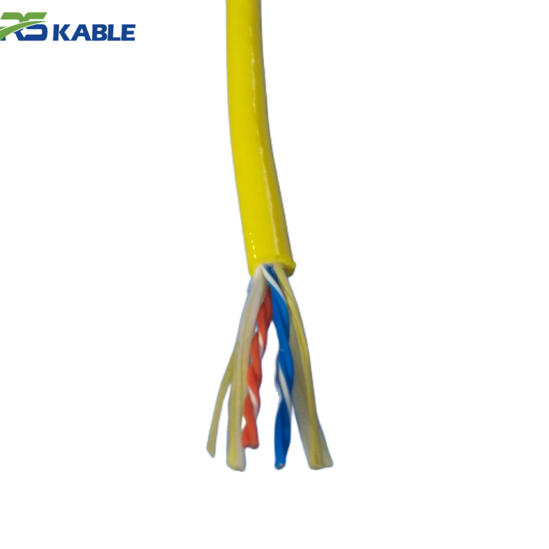
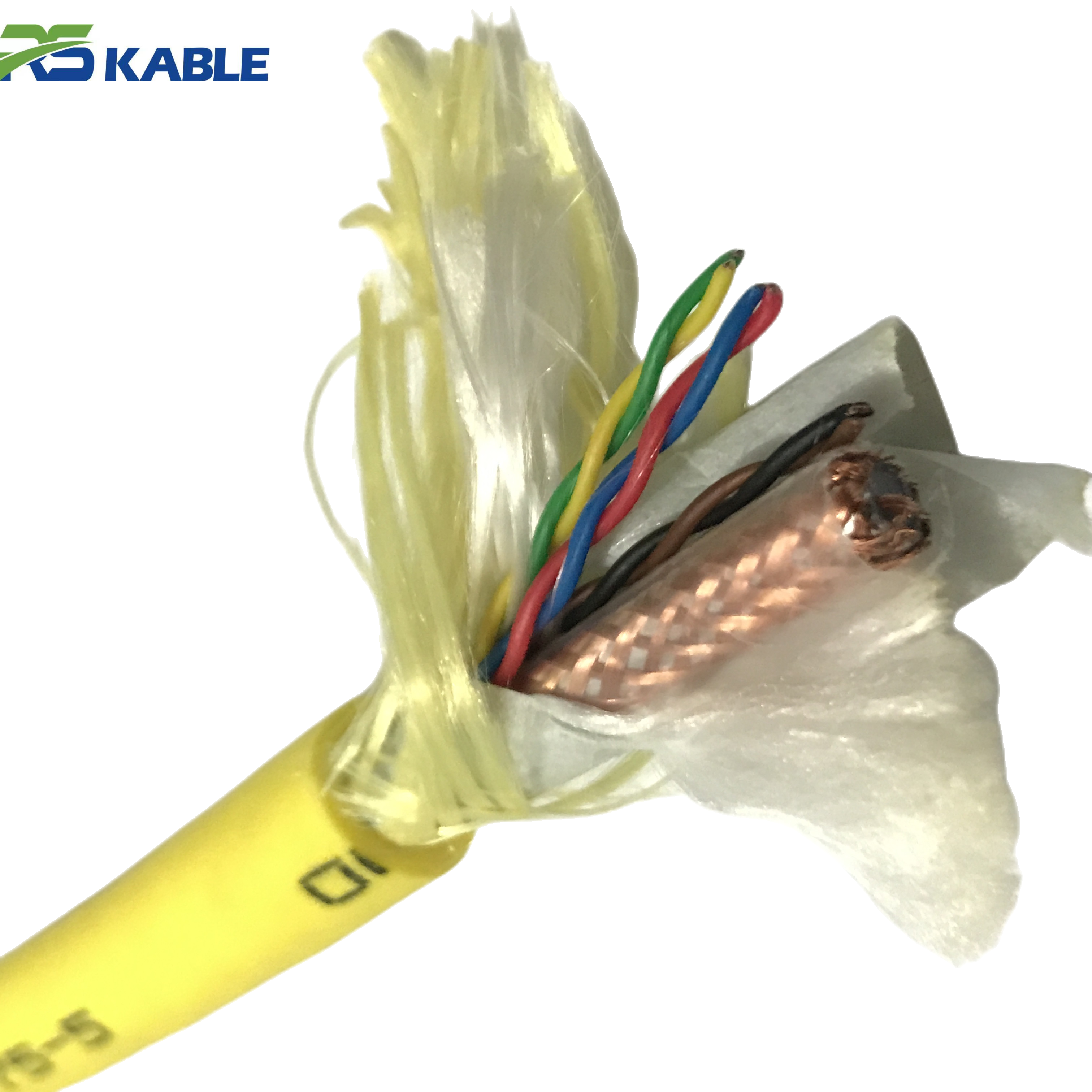
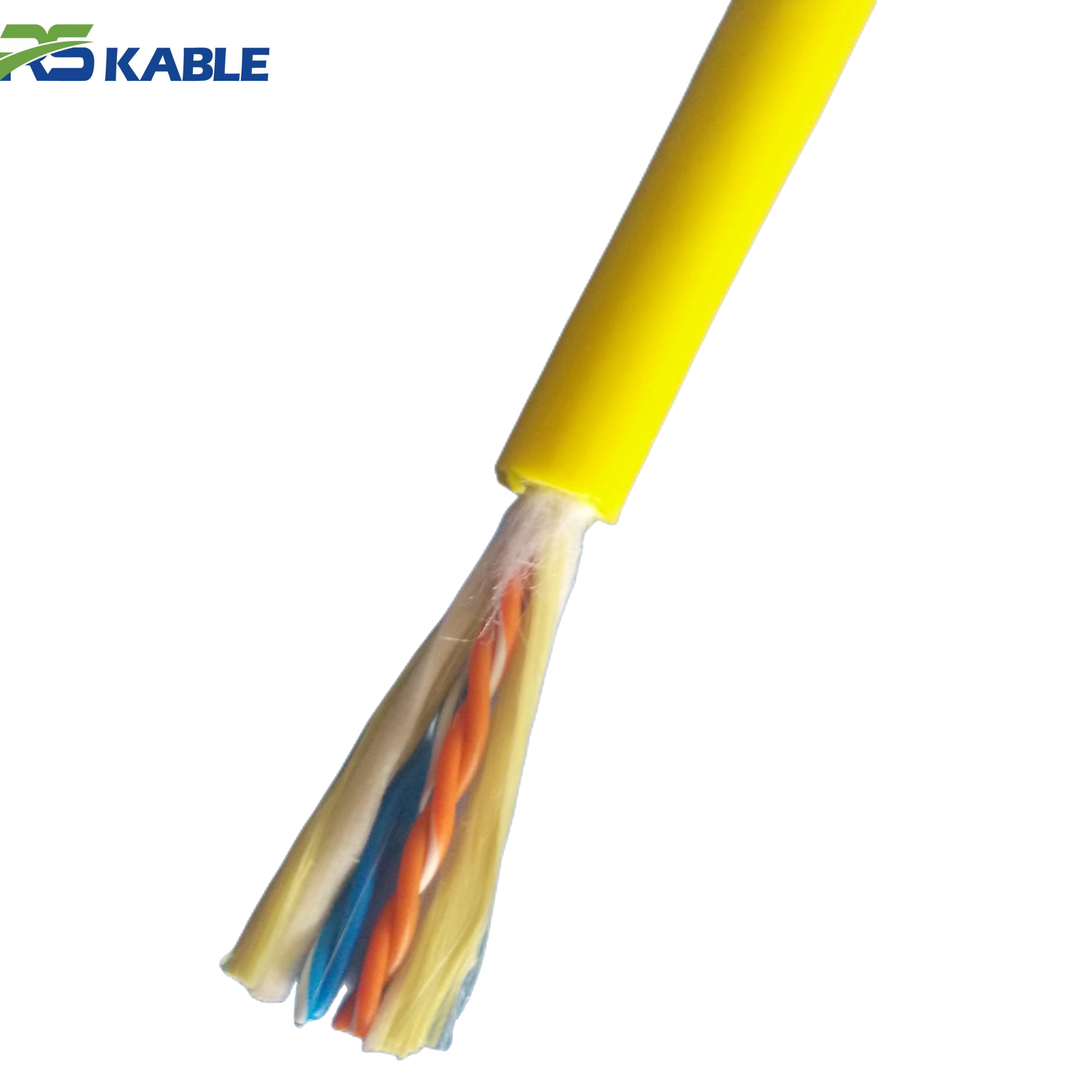
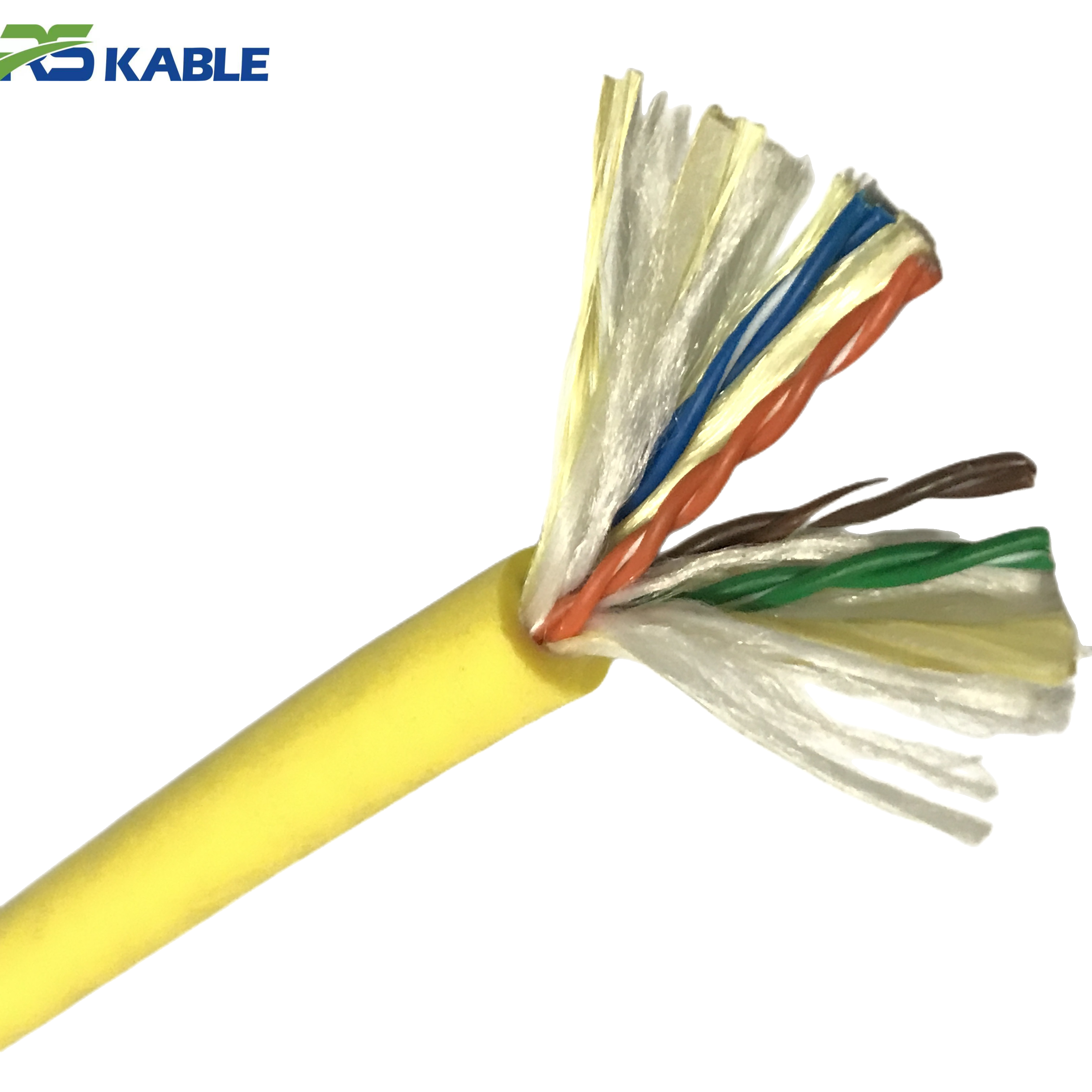
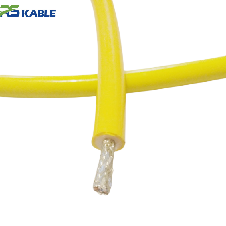
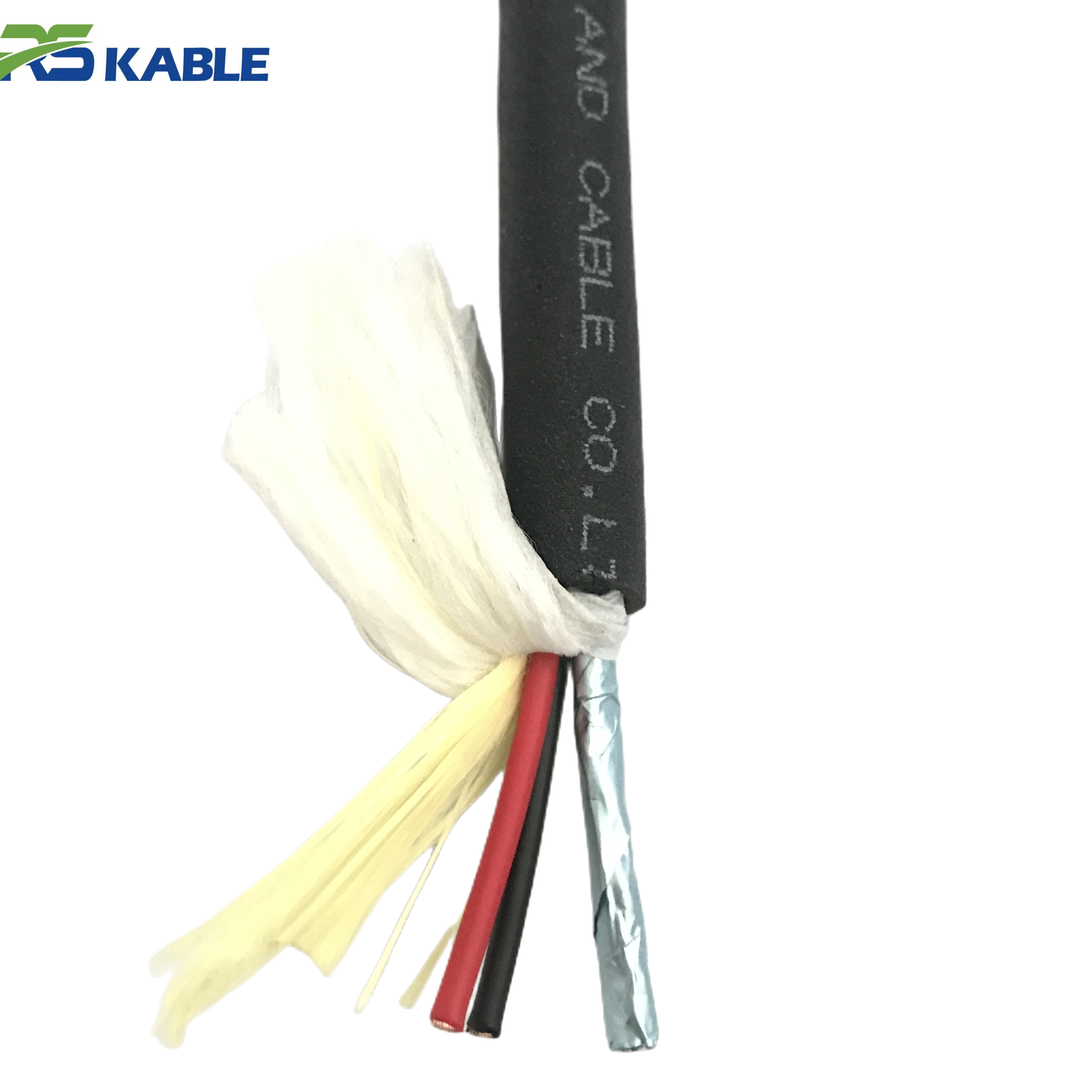
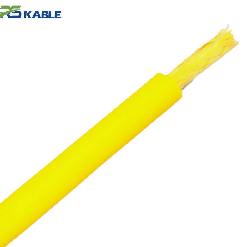
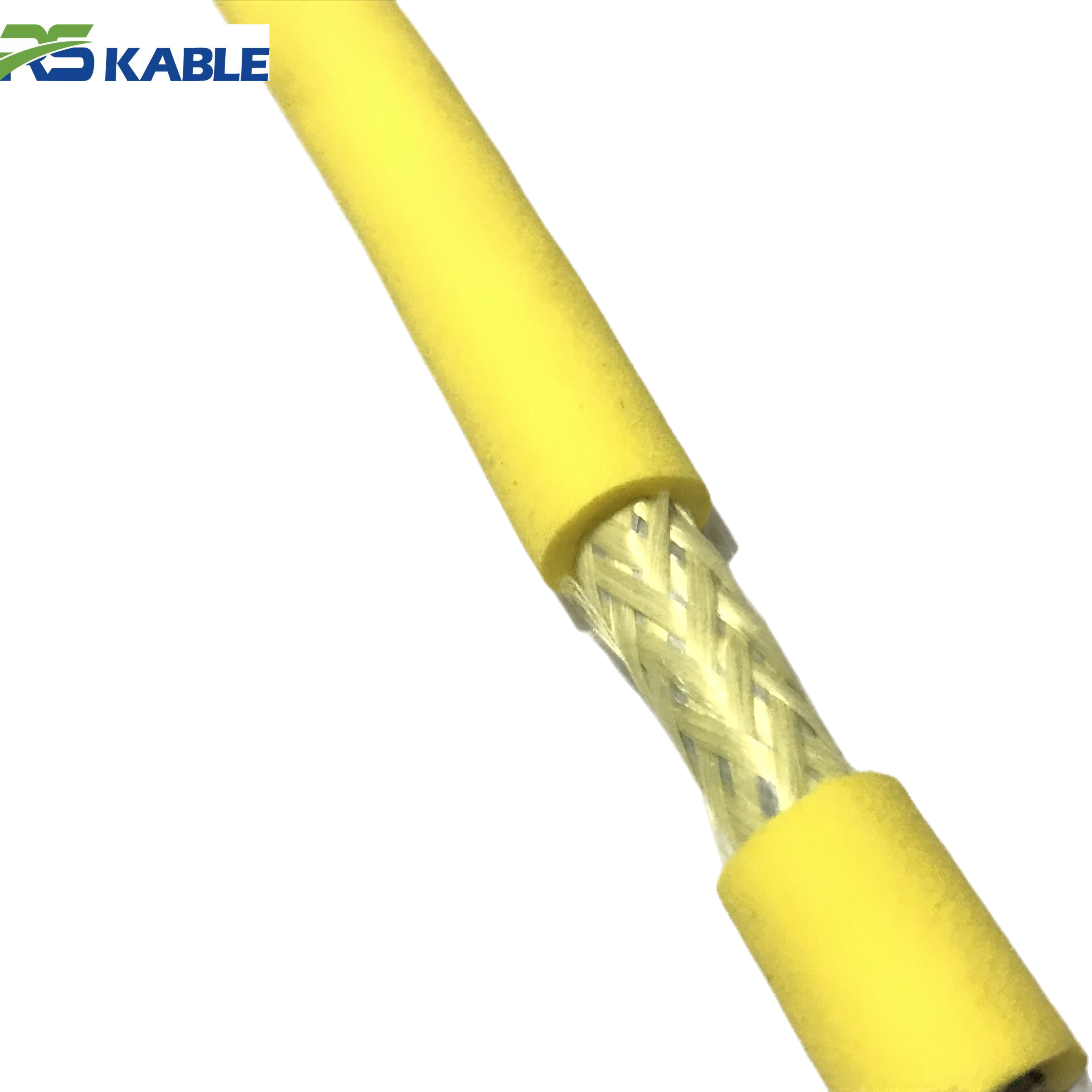
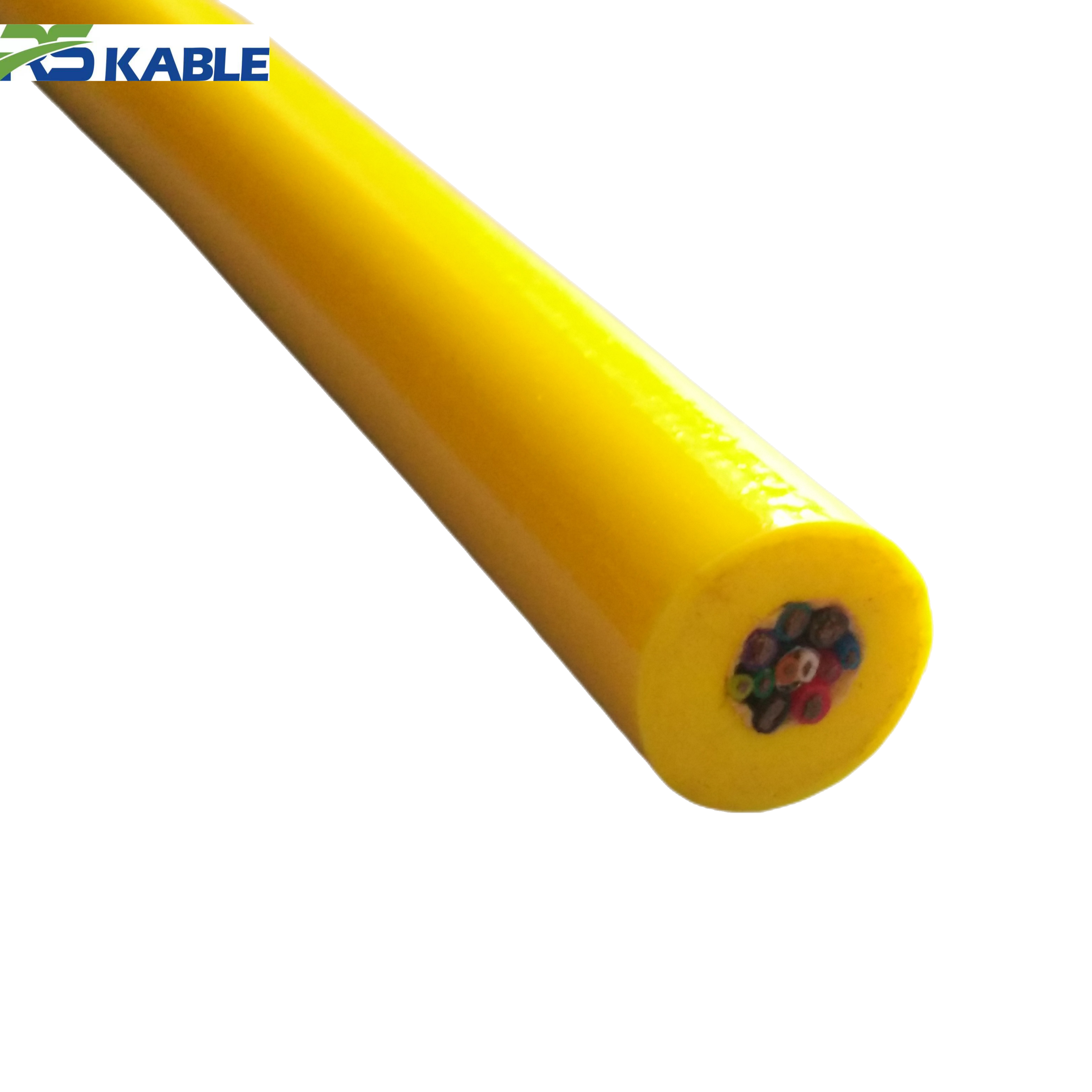
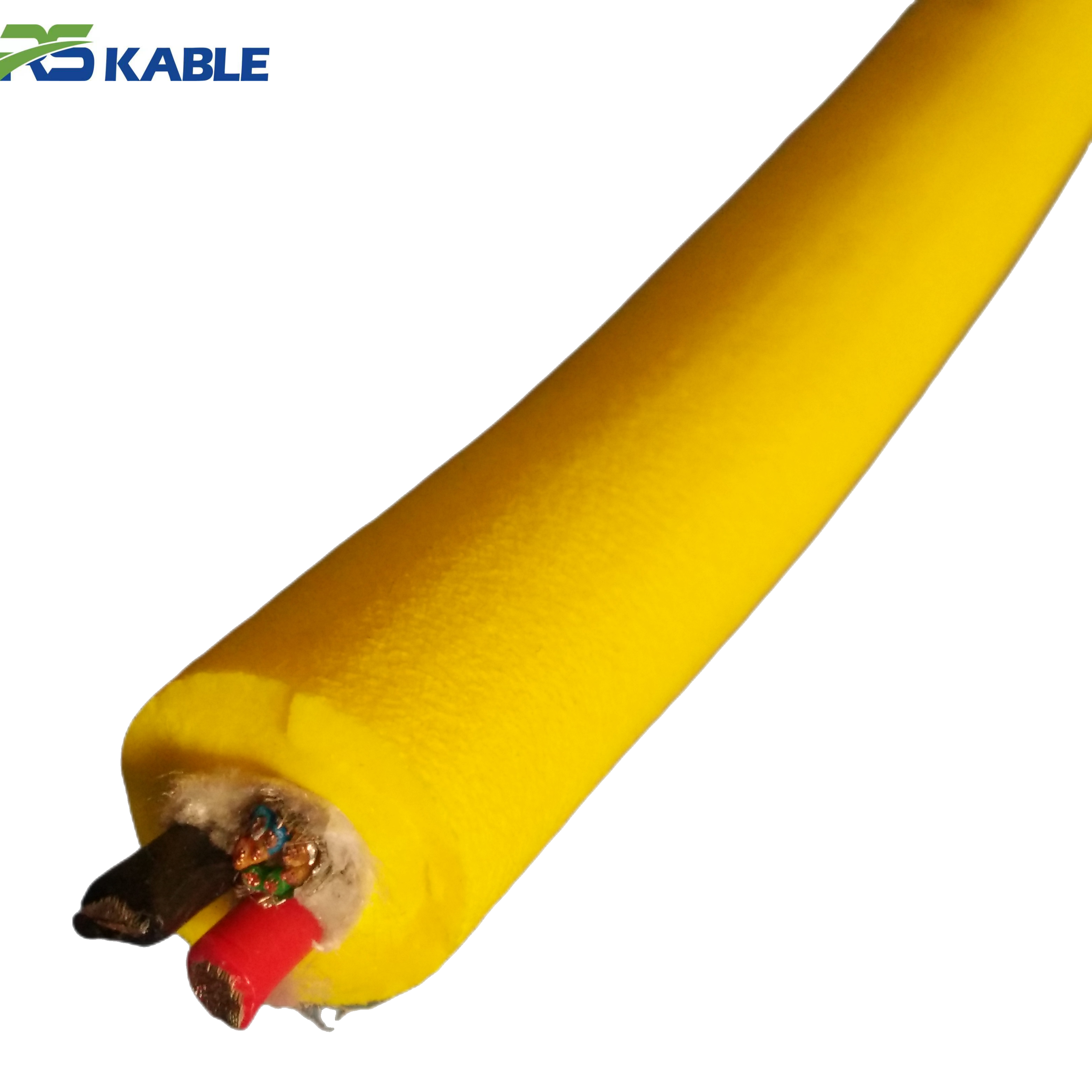
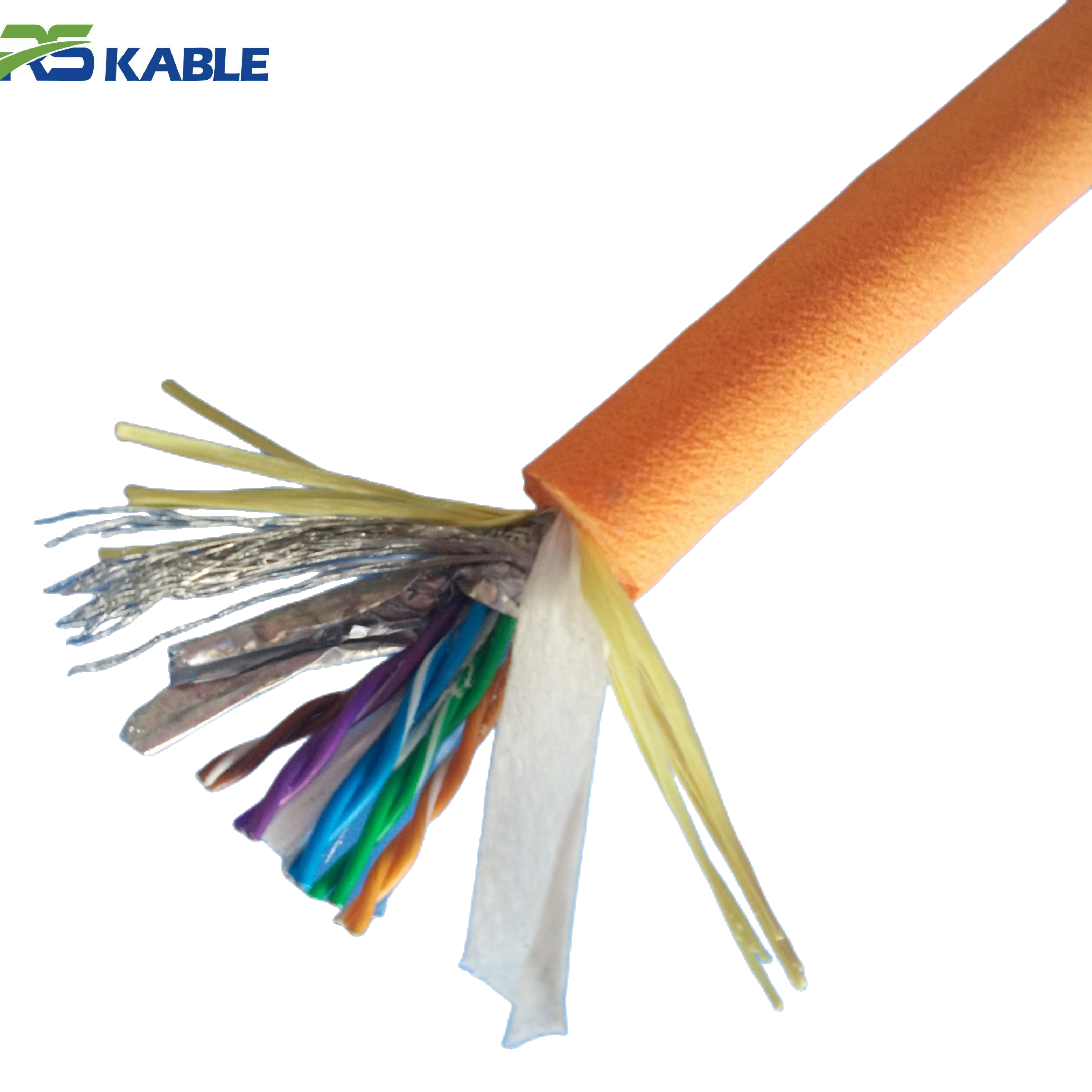
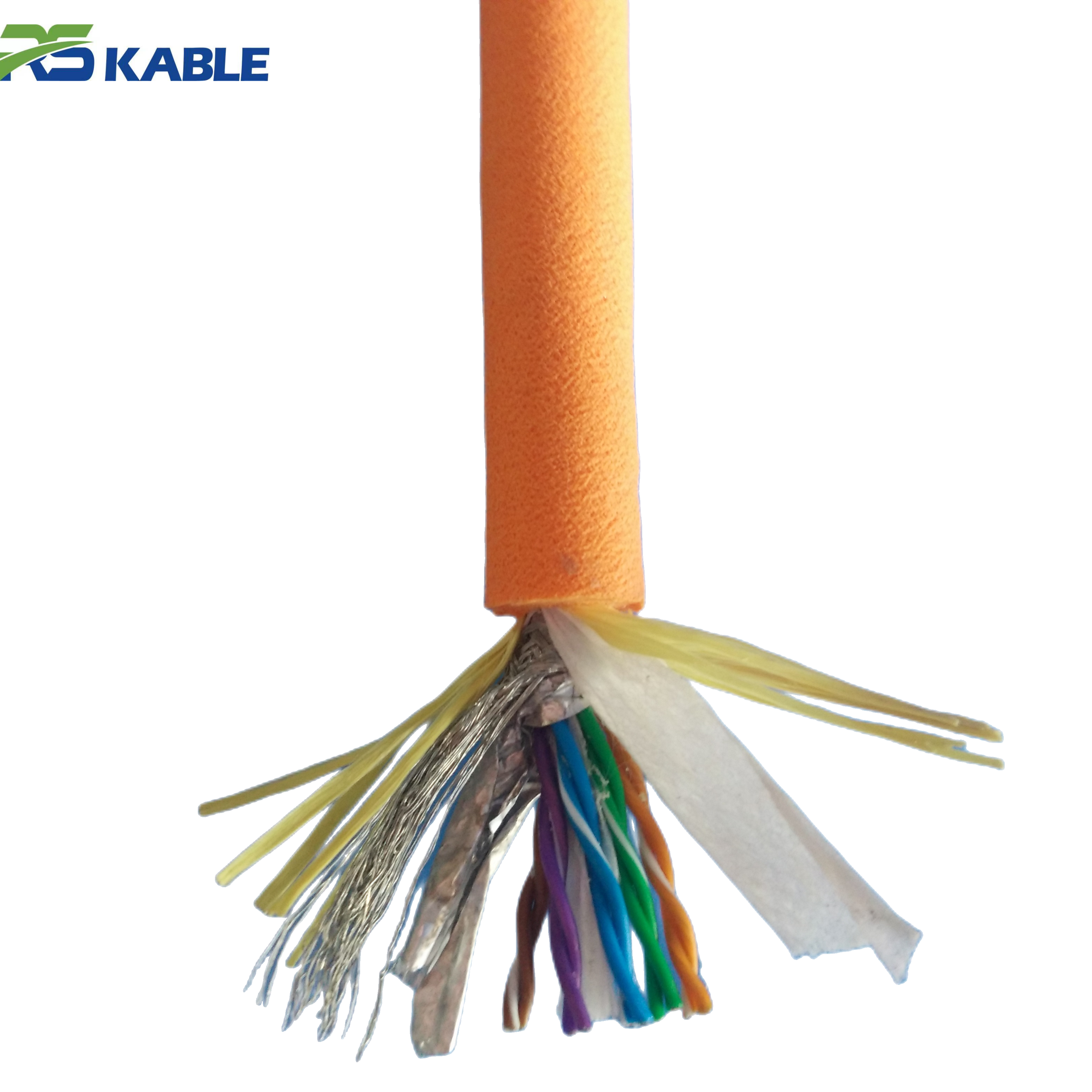
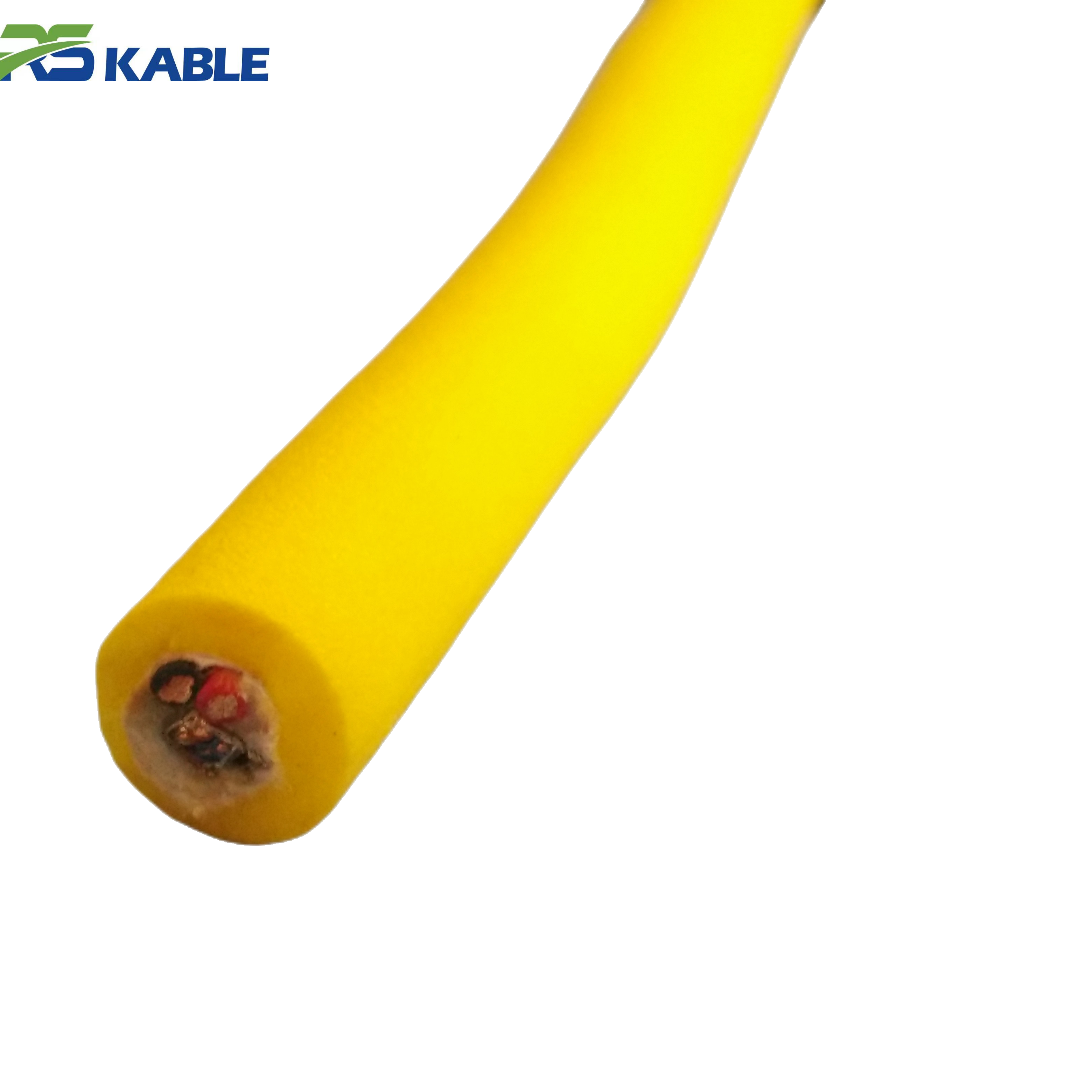
Underwater Inspection Robots ROV Cable | Low Noise Signal & Shielded Interference Protection
Engineered for professional **underwater inspection robots and ROVs**, this **neutral buoyancy cable** features a **high-density shielded structure** to ensure **low-noise signal transmission**. It provides superior protection against electromagnetic interference (EMI), delivering crystal-clear data and video feeds even in complex industrial or marine environments.
A 12-question mission brief that produces better cables (and better quotes)
Before you ask any supplier for pricing, write down answers to these. This becomes your “tether brief” and makes quotes more comparable.
-
Depth band: typical and maximum operating depth
-
Current: low / medium / strong (and whether it changes rapidly)
-
Bottom proximity: do you work close to seabed/structures most of the time?
-
Snag environment: sand, rock, debris, wrecks, pipelines, frames, offshore structures
-
Travel style: slow precision inspection vs long transits
-
Operational tolerance: is occasional bottom contact acceptable or a hard no?
-
Tether length needed: working length + operational buffer (not “as long as possible”)
-
Deployment method: manual, drum, LARS/TMS, over-the-side, A-frame
-
On-deck handling: tight spaces, sharp edges, frequent re-spooling, temperature extremes
-
Data profile: number of video streams, sensor bandwidth, latency sensitivity
-
Power profile: average and peak loads (thrusters + tools), duty cycle
-
Interfaces: connector types, termination constraints, bend-limits near penetrators
With those 12 answers, you can stop guessing and start specifying.
Pick your “cable family” first: inspection tether vs work-class vs towed
Most tethers fall into one of these operational families. Choosing the wrong family creates friction from day one.
1) Inspection-class tether (control and handling first)
Used for close-in visual inspection, survey checks, and light intervention. Priorities:
-
low drag and stable water-column behavior
-
high flex/fatigue endurance
-
abrasion resistance where contact is likely
-
reliable real-time data (often fiber)
2) Work-class tether (power and robustness first)
Used for heavier tooling, higher power draw, and higher tension events. Priorities:
-
higher tensile margin and reinforcement
-
voltage drop management under load
-
robust termination/strain relief
-
fatigue performance at high bend stress points
3) Towed / hybrid applications (geometry stability first)
Tow bodies and arrays care about tension stability and predictable catenary. Priorities:
-
consistent in-water behavior
-
drag/diameter optimization
-
stable data link for survey payloads
You can still customize within a family, but starting with the correct family keeps the design grounded.
Buoyancy strategy: where real efficiency is won
Buoyancy isn’t a checkbox; it’s a control strategy.
What you’re trying to avoid
-
Too negative: constant seabed drag, snag risk, “pulled down” vehicle feel
-
Too positive: rising loops, surface influence in shallow water, unpredictable crossings
-
Inconsistent: one section behaves differently, making handling unpredictable
A neutrally buoyant approach is often a strong choice for inspection work near structures, where bottom loops become snag points. But don’t treat “neutral” as a universal rule—some shallow, strong-current jobs intentionally prefer slightly negative behavior to reduce surface looping while still minimizing drag.
When you request a quote, don’t just ask “is it neutral?” Ask:
-
what buoyancy window is targeted?
-
how consistent is it along the length?
-
how does it behave in current (practically, not theoretically)?
This is where the right 【ROV Cable 】 starts feeling “easy to pilot” instead of “always fighting you.”
Drag and diameter: the hidden tax in current
If your ROV regularly operates in current, diameter is not a minor detail. Drag changes everything:
-
station keeping effort
-
sweep zone around structures
-
pilot workload
-
power consumption
-
precision during close inspection
The practical rule: pick the smallest diameter that still meets power, data, and tensile needs. Oversizing “for safety” often increases mission time because the pilot must compensate for sweep and drag.
If you’re unsure whether your tether is too “draggy,” look for field clues:
-
the vehicle yaws/rolls more during station-keeping
-
turns feel slow and “rubbery”
-
the tether sweeps into your work area more often than expected
Power planning: avoid the voltage-drop trap
A tether that meets “rated voltage” can still underperform when the ROV is doing real work.
What matters is delivered power at the vehicle under peak load. If your thrusters and tools spike current, voltage drop along the tether can cause:
-
reduced thrust margin
-
tool brownouts
-
unstable behavior under load
-
intermittent resets that look like electronics issues
Practical procurement approach:
-
document average and peak current
-
define the working tether length
-
ask suppliers to size conductors for your load profile, not just nominal ratings
If your project regularly runs long lengths, consider whether the system architecture (operating voltage, power distribution) should be adjusted—not just the cable.
Data architecture: pick stability, not just bandwidth
Most modern operations need reliable real-time video/telemetry. Fiber is common because it handles bandwidth and is less susceptible to electrical noise. But fiber does not magically solve reliability—terminations and bend management decide whether it stays stable.
Ask yourself:
-
How many video streams are truly needed in real time?
-
Is latency sensitive for piloting?
-
Will you add sensors later (margin planning)?
Then specify:
-
fiber count (with reasonable expansion margin)
-
preferred connector/termination constraints
-
acceptance tests (see below)
Jacket and armor: choose for your contact risk, not generic toughness
Jacket and armor choices should match the seabed and structure environment:
-
High abrasion / debris: prioritize tough outer jacket and wear resistance
-
Structure-heavy work: prioritize cut resistance + controlled sweep + snag avoidance
-
Rocky seabed: abrasion resistance and protective routing practices matter more than “thicker is better”
Polyurethane jackets are popular for abrasion resistance, but the right choice depends on your handling and environment. Armor can protect but often adds diameter and stiffness—sometimes increasing drag and reducing maneuverability.
A good spec balances:
-
durability where contact is unavoidable
-
flexibility/fatigue in moving zones
-
manageable drag in current
The most common failure signatures (and what they usually mean)
These are patterns crews see repeatedly. They’re useful both for choosing a new cable and diagnosing an old one.
1) Video/telemetry drops only when the ROV moves
Usually points to fatigue near terminations, inadequate strain relief, or repeated bend stress at a fixed point.
2) Jacket scuffing appears quickly in the same region
Often means the tether is dragging due to buoyancy mismatch, slack discipline, or an overly low catenary.
3) The ROV feels “pulled down” and needs constant lift thrust
Often indicates too-negative in-water weight or too much slack sagging the catenary.
4) Snags increase during turns near structures
Often indicates wide sweep zone (drag + sag) and slack loops falling into hazard areas.
If you’re trying to improve operational consistency, these symptoms are high-signal indicators that tether behavior is the bottleneck.

Terminations and strain relief: where you win or lose reliability
Many tethers don’t fail in the middle of the cable. They fail near the connector/termination because that’s where:
-
tension concentrates
-
bending repeats
-
handling mistakes accumulate
Procurement questions that matter:
-
How is strain relief built and tested?
-
Where is the designed “flex zone” relative to the connector?
-
What bend guidance should crews follow on deck?
-
What field failures does the supplier see most often?
If a vendor can’t talk about termination fatigue as a real topic, treat that as a risk signal.
A compact “spec sheet” you can paste into your RFQ
Include this in your request so quotes are comparable:
-
mission family: inspection / work-class / towed
-
length: required working length + buffer (justify buffer)
-
power: operating voltage, avg/peak current, duty cycle
-
data: fiber count, required bandwidth, latency sensitivity
-
buoyancy: target behavior (near-neutral / slightly negative) + consistency requirement
-
drag/diameter: maximum preferred diameter (if current is a factor)
-
tensile: minimum rating + safety margin expectations
-
jacket: abrasion/cut environment description + preference (if any)
-
bend: minimum bend radius requirements and handling constraints
-
termination: connector type, strain relief expectations, interface constraints
-
acceptance tests: electrical + fiber + visual/handling checks
This is how you get fewer generic quotes and more mission-fit recommendations.
Acceptance & commissioning: how to verify before it costs vessel time
A tether can look great on a spool and still fail offshore because the weak points weren’t checked.
Incoming inspection (on deck)
-
jacket and diameter uniformity, no handling damage
-
length marking and ID labeling consistency
-
termination strain relief integrity (no sharp transitions)
Electrical checks (fit-for-purpose)
-
continuity and insulation checks appropriate to your system
-
verify under-load behavior if feasible (even partial load tests help)
Fiber checks (when applicable)
-
insertion loss and continuity verification
-
document baseline results before deployment for troubleshooting reference
Handling check
-
confirm your deck setup can respect minimum bend radius
-
confirm routing avoids pinch points, sharp edges, and repeated tight turns
This is where a good 【ROV Cable 】 becomes a predictable asset instead of an offshore unknown.
Quick selection shortcuts (when you need a decision fast)
-
If you do close inspection near structures, prioritize buoyancy control + low drag + abrasion resistance + termination fatigue design.
-
If you do high-power work-class tasks, prioritize tensile margin + voltage drop management + robust terminations (then optimize drag).
-
If your crew often says “we’re fighting the tether,” focus first on buoyancy strategy and drag/diameter, not electronics.
FAQ
How many fibers do I need in an ROV tether?
Start with today’s real-time video/telemetry needs, then add modest expansion margin. The right number depends on system architecture and future sensors.
Is neutrally buoyant always best?
Not always. Near-neutral often improves inspection handling, but some shallow strong-current operations prefer slightly negative to reduce surface looping—mission context decides.
Why do dropouts happen only during movement?
That pattern commonly points to fatigue or strain relief issues near terminations, or repeated bend stress at a fixed routing point.
Should I choose armored or unarmored tether?
Armor can improve protection but usually adds diameter and stiffness (more drag). Choose armor when contact/cut risks justify the tradeoff.
What should I test before first deployment?
Do visual jacket/termination checks, fit-for-purpose electrical checks, fiber checks (if used), and confirm your handling setup respects bend radius constraints.