
Underwater Towing Cable Manufacturer | Heavy-Duty Subsea Drag Cable for Marine & ROV Applications
The RST-UTC Series Underwater Towing Cable is a high-performance subsea drag cable engineered for demanding towing conditions, including hydrodynamic load, deepwater pressure, seabed abrasion, and torsional stress.
Available in electro-mechanical (Kevlar 2–8 kN), electro-optical (up to 3,000 m / 6,000 m depth), and double-armoured (steel 12–20 kN) configurations, it supports ROV umbilicals, AUV towing, seabed surveys, and heavy offshore operations.
A neutral buoyancy version (0.98 g/cm³ ±0.02) reduces drag for precision AUV and MCM missions. Kevlar models feature torque-balanced construction (≤0.5°/m) for stable performance in sensitive survey systems.
The polyether PUR jacket ensures long-term seawater resistance, validated by 5,000-hour immersion testing. All cables are pressure-tested to 1.5× working depth, with optical versions supplied with OTDR reports.
Certified to ISO 9001:2015, compliant with CE, RoHS, REACH, with optional DNV/BV approvals for offshore projects.
Underwater Towing Cable Manufacturer | Heavy-Duty Subsea Drag Cable for Marine & ROV Applications
Product Series: RST-UTC │ Category: Subsea & Underwater Cables │ Reviewed by: Rousheng Subsea Engineering Team
|
6,000 m Max depth rating |
8 kN Kevlar tensile strength |
0.98 g/cm³ Near-neutral buoyancy |
−40°C Cold seawater rated |
24 hr Quote turnaround |
Underwater towing cable is among the most mechanically complex cable categories in marine engineering: it must simultaneously bear the hydrodynamic drag load of the towed body, resist abrasion from seabed contact and winch drum cycling, transmit power and data signals without interruption, and maintain structural integrity at pressures that increase by 1 bar for every 10 m of depth — all in an environment where a cable failure means the loss of an expensive deployed asset and potentially an aborted mission. Selecting the wrong cable for towing duty is not a recoverable mistake at 3,000 m depth.
The RST-UTC series is Rousheng’s dedicated underwater towing and drag cable line, developed over more than eight years of subsea project collaboration with ROV operators, oceanographic survey companies, and naval research institutions. Each model is engineered from the tensile member outward: Kevlar or steel armour carries the mechanical load; individually screened copper or optical fibre cores carry the signals; and a polyurethane outer jacket chosen specifically for seawater hydrolysis resistance and hydrodynamic profile encloses the whole.
This page details the construction choices behind each RST-UTC model, the project environments where they are deployed, and a step-by-step cable sizing method that accounts for the towing-specific parameters — drag load, catenary angle, and depth pressure — that generic cable selection tools ignore.
Page Contents
- Depth Rating Visual Guide — Which Model for Which Depth
- Model Range & Specifications
- The Four Engineering Demands of Subsea Tow Cable
- Project References — Real Deployments
- Layer-by-Layer Construction with Engineering Rationale
- Material Comparison: PUR vs. Polyethylene vs. Rubber for Subsea
- Technical Parameters (Electrical, Optical, Mechanical)
- Towing Load Sizing Guide + Worked Example
- FAQ — Real Questions from Marine Engineers
- Manufacturer Credentials
- Request a Quote or Sample
Depth Rating Guide — Which RST-UTC Model for Which Operation
|
0–300 m Coastal / Harbour ROV RST-UTC-S1 |
300–1,000 m Offshore ROV / Survey RST-UTC-S2 |
1,000–3,000 m Deep Survey / Science RST-UTC-D1 |
3,000–6,000 m Full Ocean Depth RST-UTC-D2 |
Depth ratings are working depth at rated hydrostatic pressure test factor 1.5×. All models maintain full electrical and optical performance at rated depth. Custom depth ratings available on request.
RST-UTC Series — Model Specifications
|
Model |
Type |
Depth Rating |
Tensile Strength |
OD |
Power Element |
Data Element |
Buoyancy |
Primary Application |
|
RST-UTC-S1 |
Electro-mechanical |
300 m |
2 kN Kevlar |
14.5 mm |
2×1.5 mm² OFC |
4×0.25 mm² screened pairs |
Slightly negative |
Shallow ROV, harbour survey |
|
RST-UTC-S2 |
Electro-mechanical |
1,000 m |
4 kN Kevlar |
16.2 mm |
2×2.5 mm² OFC |
4×0.25 mm² + RS-485 pair |
Near-neutral (foam fill) |
Offshore ROV, coastal tow array |
|
RST-UTC-D1 |
Electro-optical |
3,000 m |
6 kN Kevlar |
18.8 mm |
3×2.5 mm² OFC |
2×SM fibre + 4 pairs |
Near-neutral |
Deep survey, science payload |
|
RST-UTC-D2 |
Electro-optical |
6,000 m |
8 kN Kevlar |
21.4 mm |
3×4.0 mm² OFC |
4×SM fibre + 4 pairs |
Near-neutral |
Full ocean depth, hadal ROV |
|
RST-UTC-A1 |
Armoured electro-mech. |
1,000 m |
12 kN steel wire |
22.0 mm |
4×2.5 mm² OFC |
8 pairs screened |
Negative (steel armour) |
Trawl-resistant, seabed drag |
|
RST-UTC-A2 |
Double armour electro-opt. |
3,000 m |
20 kN steel wire |
26.5 mm |
4×4.0 mm² OFC |
4×SM fibre + 8 pairs |
Negative |
Deep trawl, heavy intervention |
|
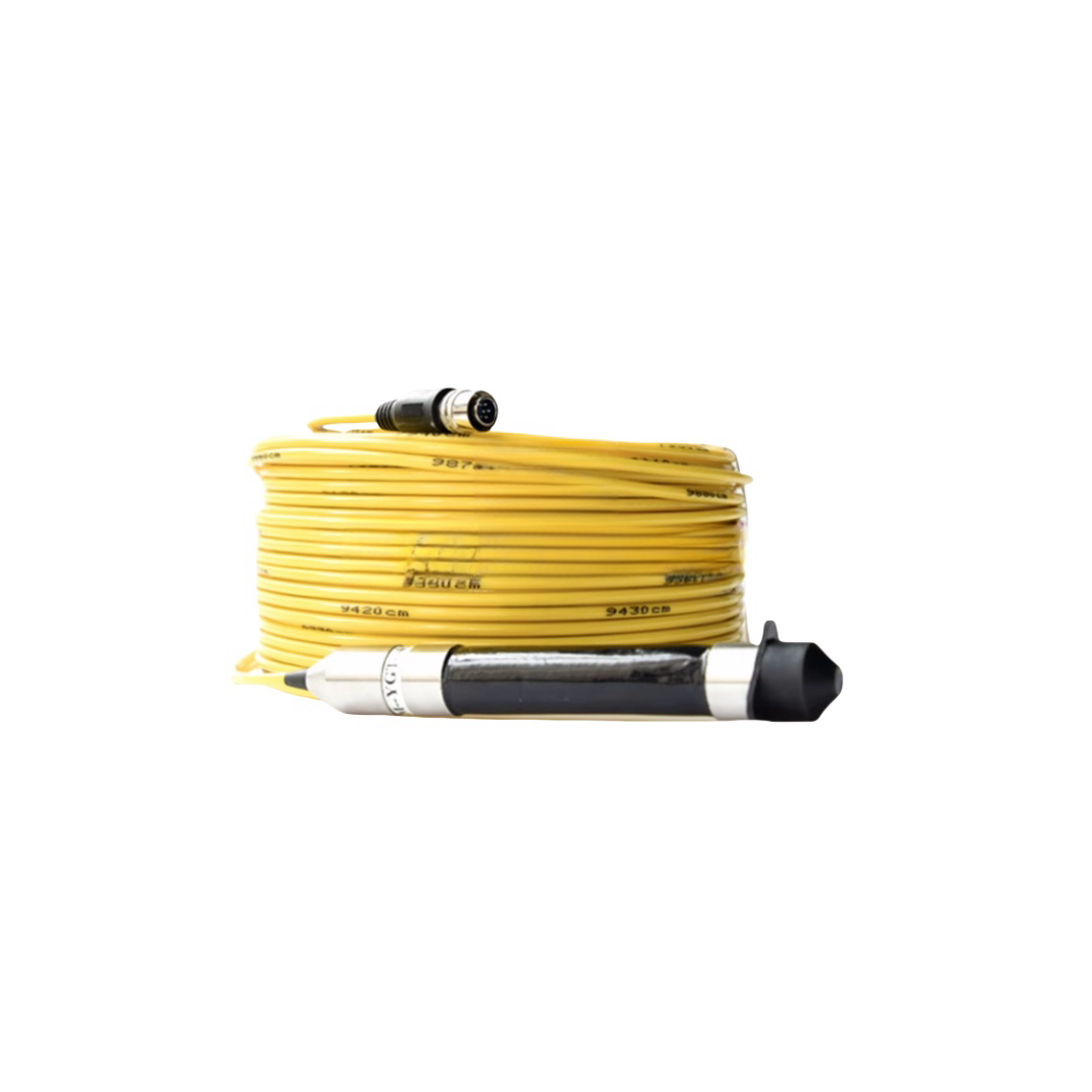
RST-UTC-NB |
Neutral buoyancy |
500 m |
3 kN Kevlar |
20.0 mm |
2×1.5 mm² OFC |
EtherCAT pair + 4 pairs |
True neutral (±0.02 g/cm³) |
AUV umbilical, mine countermeasures |
|
RST-UTC-OEM |
Custom |
Per spec |
Per spec |
Per spec |
Per spec |
Per spec |
Per spec |
Offshore, naval, oceanographic custom |
SM fibre = ITU-T G.657.A1 single-mode. Kevlar tensile members: Kevlar 49 (high modulus, ≤1.5% elongation at rated load). Steel armour: galvanised or stainless wire, layer-wound. Neutral buoyancy achieved by syntactic foam fill or closed-cell PUR foam compound.
The Four Engineering Demands of Subsea Tow Cable
Most cable selection guides for subsea work focus on depth rating and electrical specification. These are necessary but not sufficient. Underwater towing adds four mechanical demands that do not arise in fixed-subsea or reel-drum applications, and that collectively determine whether a cable survives its intended mission profile.
|
Demand |
What Happens |
Failure Consequence |
RST-UTC Engineering Response |
|
Hydrodynamic tow load |
A cable towed at 3 knots through seawater at a 30° catenary angle develops a drag force determined by the cable’s drag coefficient (Cd ≈1.1 for a round cable), its diameter, length, and vessel speed. At 500 m depth on a 600 m cable at 3 kts, tensile load at the surface termination routinely exceeds 2–4 kN. |
If the tensile member is undersized, copper conductors carry residual load. Copper elongates under sustained tension >200 N per mm² conductor cross-section, increasing resistance progressively until signal loss or open-circuit failure. |
Kevlar 49 parallel-lay tensile members rated to 2–8 kN (RST-UTC-S/D). Steel wire armour rated to 12–20 kN (RST-UTC-A). Tensile members terminate at mechanical cable grips, never at conductor terminations. Load path bypasses copper entirely. |
|
Hydrostatic pressure |
Hydrostatic pressure increases by 0.1 MPa per 10 m. At 3,000 m, the cable jacket and all internal elements are subject to 30 MPa (300 bar) of isotropic compression. Voids, trapped air, and poorly bonded layers collapse under this pressure, damaging insulation. |
Jacket collapse into air voids causes insulation deformation and eventually electrical short between adjacent cores. In optical cables, micro-bending from jacket pressure causes attenuation spikes that disable the data channel. |
Gel-filled interstices: all voids between cores and jacket are filled with non-migrating petroleum gel (water-blocking compound), which is incompressible and transmits hydrostatic pressure uniformly without concentration. Pressure-tested to 1.5× rated depth before shipment. |
|
Seabed abrasion & snag |
Survey tow cables that contact the seabed — particularly in geophysical tow operations where the cable is dragged across rock, coral, or gravel — experience abrasive contact that removes jacket material at contact points. Cable-over-rock snags create concentrated bending loads that can exceed the cable’s minimum bend radius. |
Jacket abrasion exposes braid armour or, in non-armoured cables, core insulation directly to seawater. Seawater ingress into a non-watertight core causes immediate electrical failure. A single over-rock snag on a thin-walled cable can cause kink damage that is not recoverable. |
Abrasion-resistant PUR outer jacket (Taber CS-17 ≥400 cycles). Steel armour variants (RST-UTC-A) add mechanical snag resistance. All RST-UTC models are longitudinally watertight: water-blocking gel and tape prevent seawater migration beyond any single jacket breach. |
|
Torsional self-rotation |
Non-torque-balanced cables rotate about their long axis under tensile load, causing the towed body to spin. This is caused by helical lay geometry converting tension into torsional moment. At high tension, cable rotation rate can exceed 1 rev/min, making instrument platforms unusable. |
Self-rotation degrades navigation data from attitude sensors, wraps umbilical hoses on ROVs, and on passive tow arrays destroys the hydrophone calibration geometry. It is a mission-ending failure mode. |
Torque-balanced design: RST-UTC Kevlar models use counter-wound tensile yarn layers of equal pitch angle in opposite directions. The opposing torsional moments cancel, producing a cable that does not rotate under tensile load. Validated to ≤0.5°/m rotation at rated load. |
Project References — RST-UTC Deployments
Customer identities withheld at client request. Technical specifications are accurate and can be verified under NDA by qualified organisations.
|
Project |
Operation |
Cable Deployed |
Key Technical Challenge |
Outcome & Duration |
|
Oceanographic research vessel, North Atlantic |
Towed CTD rosette survey, 2,800 m max depth, 4-knot tow speed |
RST-UTC-D1 (3,000 m rated, 6 kN Kevlar, 2×SM fibre + 4 pairs) |
Previous supplier’s cable developed fibre attenuation spikes below 2,000 m due to jacket micro-bending under hydrostatic pressure. RST-UTC-D1 with gel-filled interstices showed <0.1 dB/km additional attenuation at 2,800 m. |
5 research cruises completed, 2022–2024. Cable still in service. |
|
Naval MCM (mine countermeasures) unit, European Navy |
AUV umbilical, 300 m depth, zero-rotation requirement for INS navigation |
RST-UTC-NB (neutral buoyancy, 3 kN Kevlar, torque-balanced) |
Self-rotation from non-torque-balanced umbilical was corrupting the AUV’s INS attitude data at rotation rates >0.3°/m. RST-UTC-NB measured at <0.2°/m rotation at 2.5 kN tension in tank testing. |
Adopted as standard umbilical for the MCM programme. 12 units delivered 2023. |
|
Geophysical survey contractor, South China Sea |
2D seismic streamer lead-in section, seabed tow, 120 m depth |
RST-UTC-A1 (armoured, 12 kN, 8 screened pairs) |
Seabed drag operation in coral-rock terrain required snag-resistant armour and longitudinal water-blocking after partial jacket abrasion events. RST-UTC-A1 sustained 3 rock-snag events without electrical failure due to gel-filled watertight construction. |
Operating season completed without unplanned replacement. 2023. |
|
Deep-sea mining technology company, Pacific |
Pilot mining system umbilical, 4,500 m depth, 15 kN design tensile load |
RST-UTC-A2 (double armour, 20 kN steel wire, 4×SM fibre) |
No commercially available cable met the combined requirement of 4,500 m depth, 15 kN tensile margin, and single-mode fibre for real-time HD video. OEM custom cross-section developed jointly with client engineering team over 6-week design sprint. |
Sea trials completed 2024. Production order placed. |
|
Offshore wind O&M contractor, North Sea |
Cable-lay ROV umbilical, monopile J-tube inspection, 60 m depth |
RST-UTC-S2 (1,000 m rated, 4 kN Kevlar, near-neutral buoyancy) |
High-current North Sea environment required near-neutral buoyancy to reduce ROV thruster load during station-keeping. Near-neutral RST-UTC-S2 reduced umbilical drag force by 38% versus the contractor’s previous negative-buoyancy cable. |
ROV payload capacity increased by equivalent margin. Ongoing framework supply since 2023. |
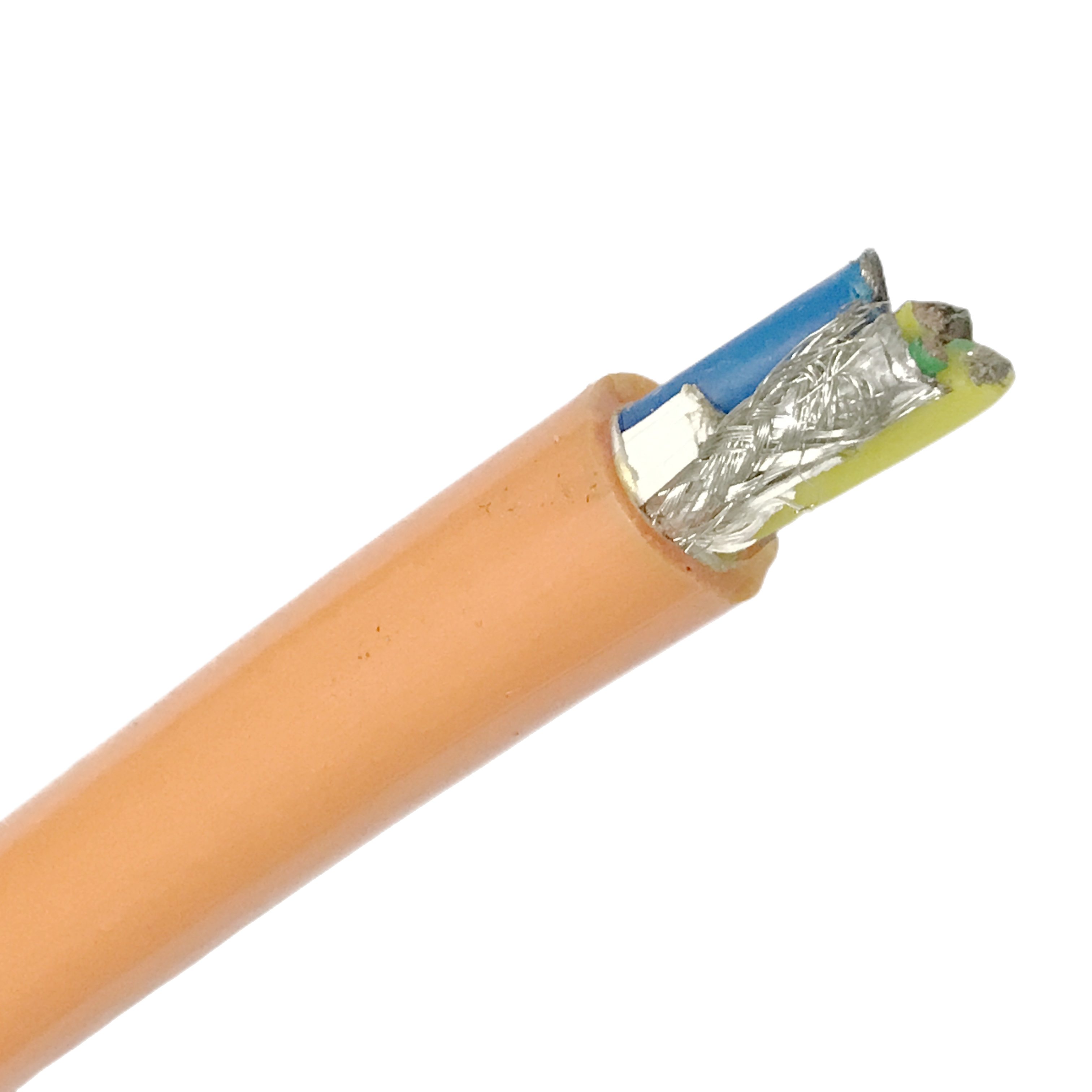
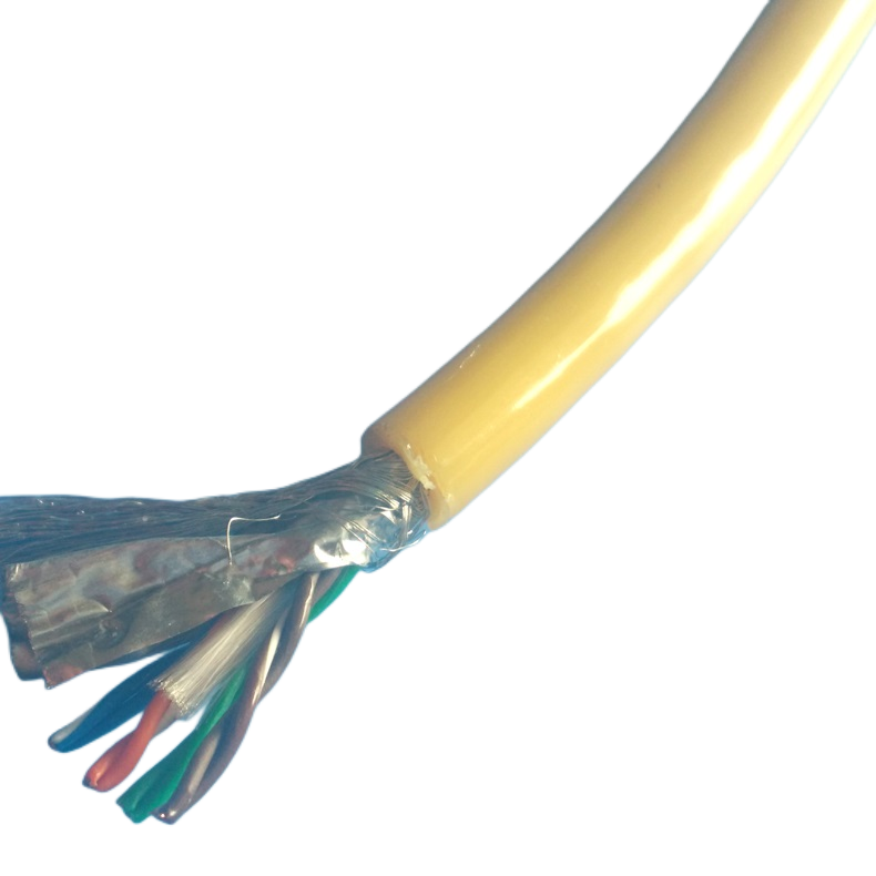
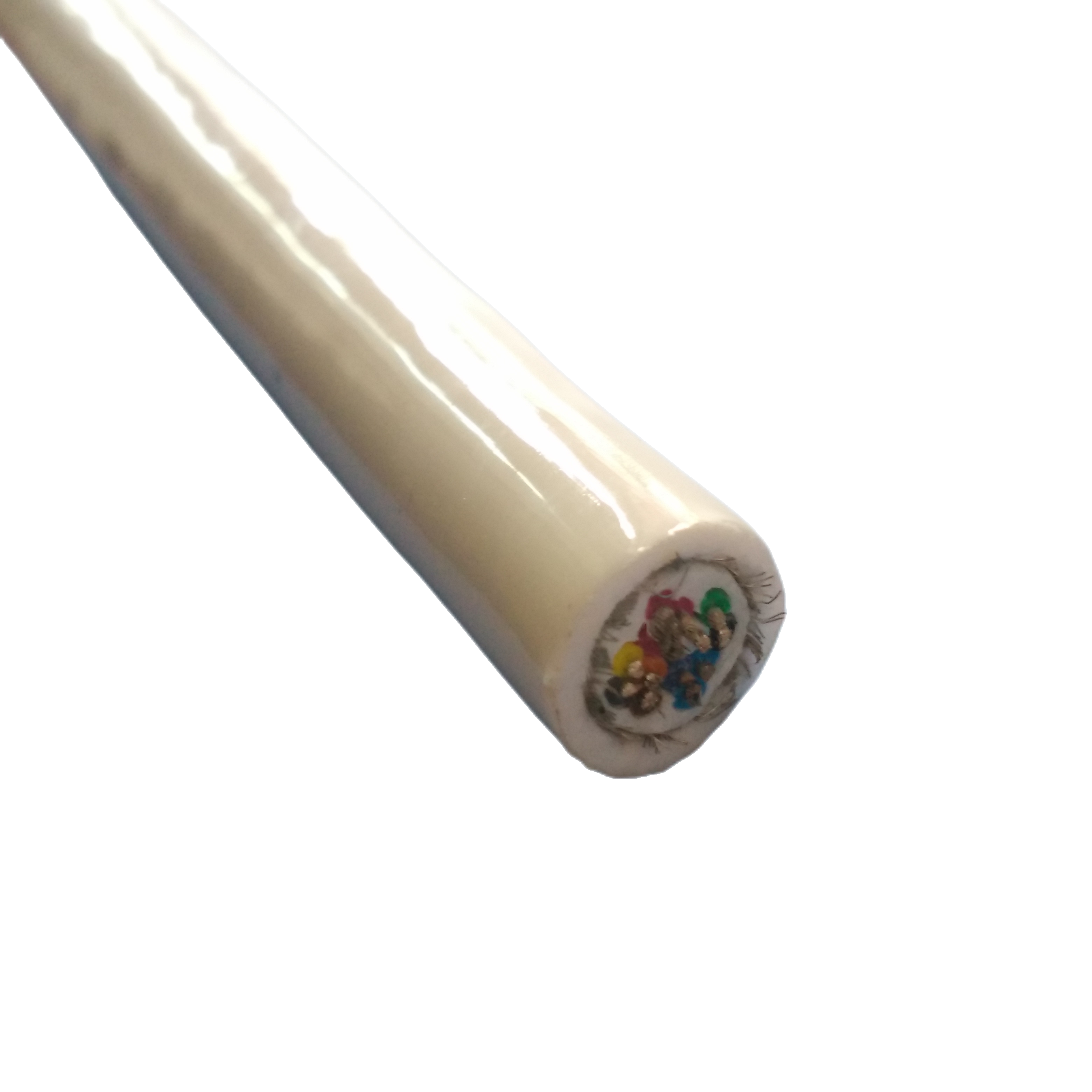
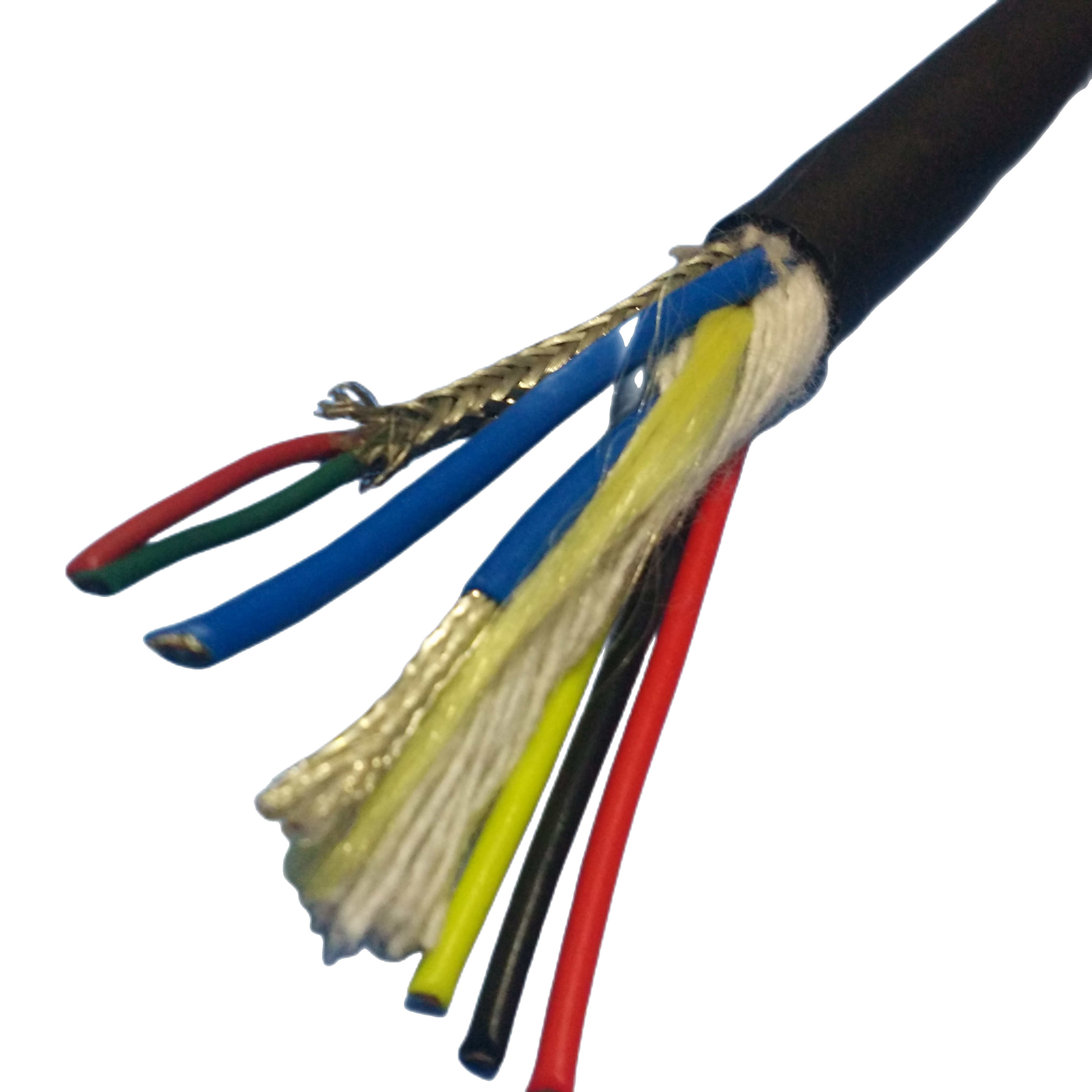
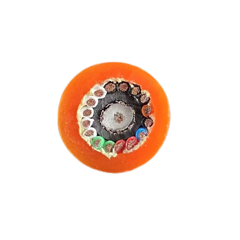
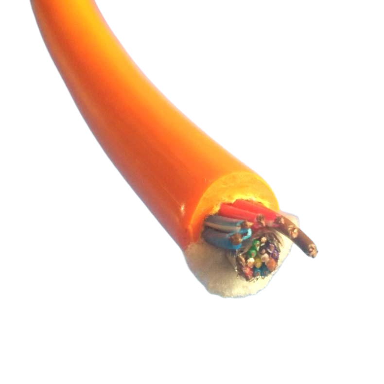
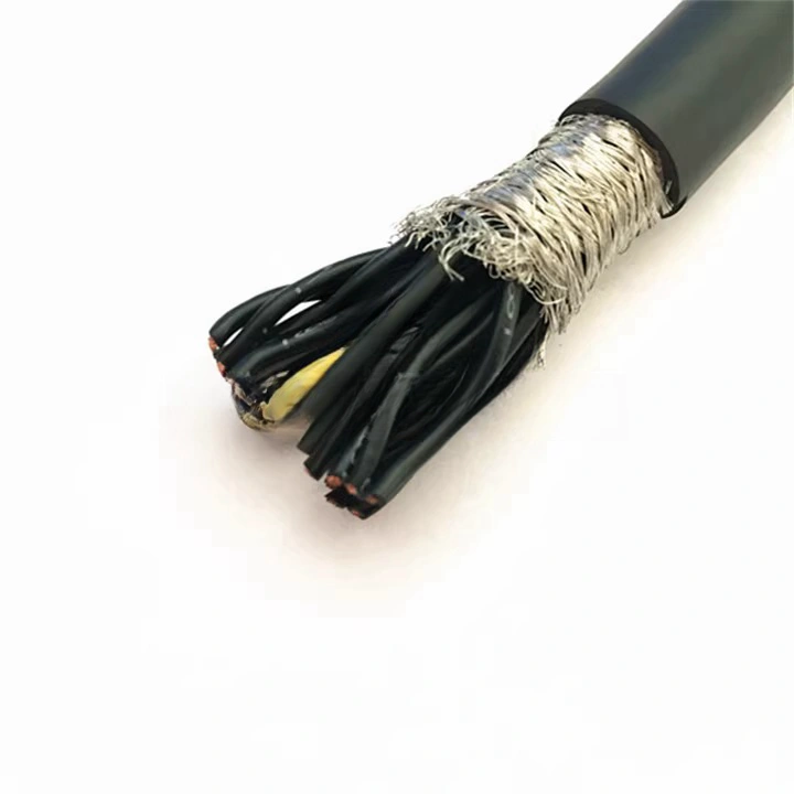
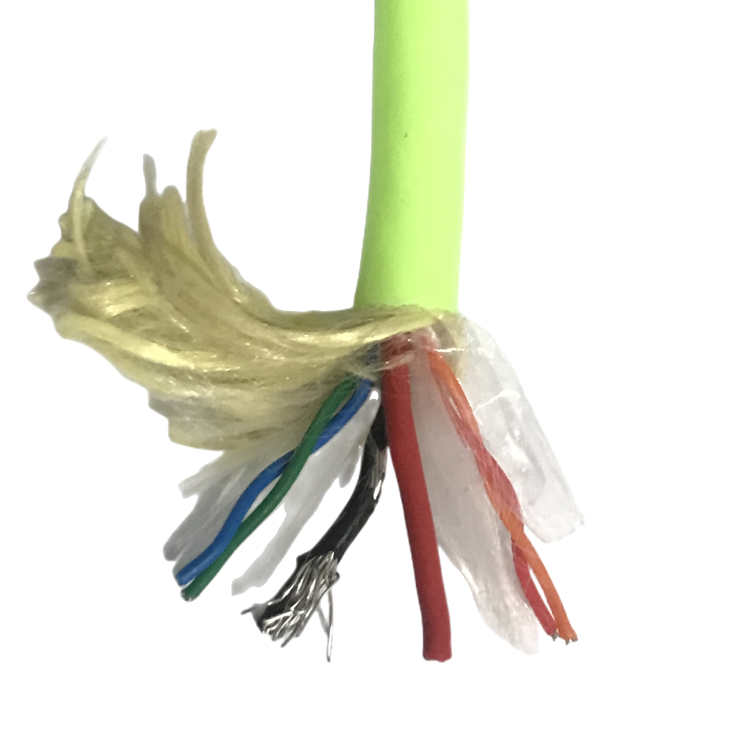
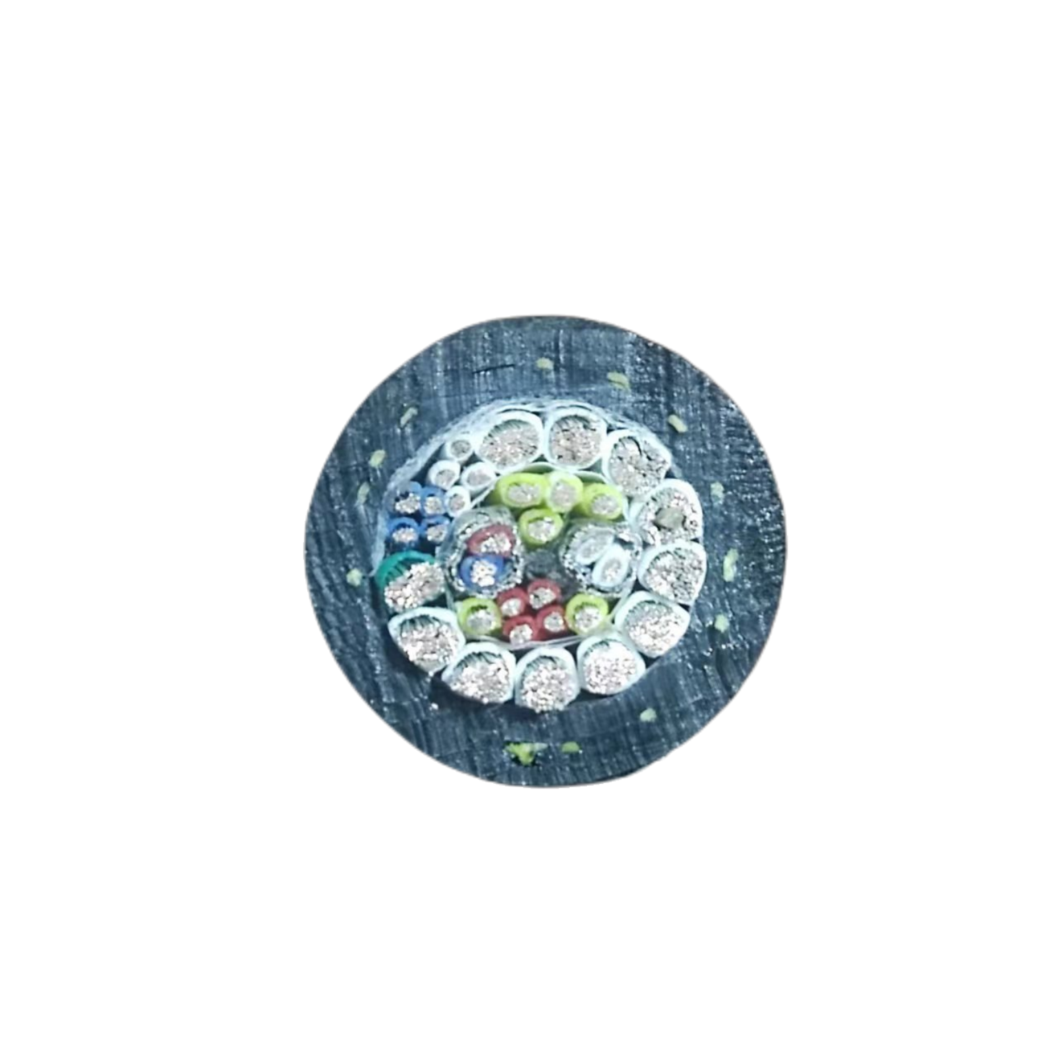
Construction — Layer-by-Layer Engineering
|
Layer |
Material / Spec |
Standard |
Engineering Rationale |
|
Optical fibre cores (D & NB models) |
ITU-T G.657.A1 single-mode fibre. Bend-insensitive design. Tight-buffered (900 μm) or loose-tube (gel-filled). Fibre count: 1–12 per element. |
ITU-T G.657.A1; IEC 60793-2-50 |
G.657.A1 bend-insensitive fibre tolerates the minimum bend radii imposed by drum winding and catenary geometry without inducing bend-loss spikes. Loose-tube gel fill provides hydrostatic pressure equalisation, preventing the micro-bending that caused failures in the North Atlantic project (see Project References). |
|
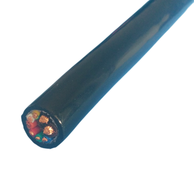
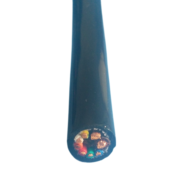
Copper power/signal conductors |
Bare OFC, IEC 60228 Class 5 or 6. Cross-section: 0.25 mm² (signal) to 4.0 mm² (power). Signal pairs individually twisted (twist rate 40–60 mm/turn) and screened (Al-foil + drain wire). |
IEC 60228:2004; IEC 61156-5 |
Individually screened pairs isolate signal channels from power conductors and from seawater-induced galvanic noise. Al-foil screen is bonded to the pair geometry — not floating — to prevent screen-to-core capacitive imbalance that degrades RS-485 and EtherCAT signal quality at long cable lengths. |
|
Water-blocking layer |
Non-migrating petroleum water-blocking gel in all interstices. Water-blocking tape (SAP-coated) over assembled core bundle. |
IEC 60794-1-2 Method F5B; IEC 60502 |
The gel is formulated to remain viscous and non-migrating from ∔0°C to +60°C — covering the full range from Arctic seabed temperature to deck-handling in tropical conditions. SAP tape provides secondary longitudinal water blocking: if the gel is displaced by a jacket breach, the tape swells on seawater contact and seals the breach locally. Without longitudinal water blocking, a single jacket cut in an un-armoured cable leads to full flooding of the cable length within minutes. |
|
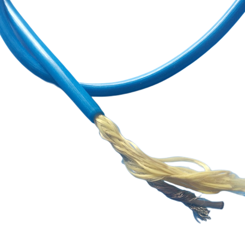
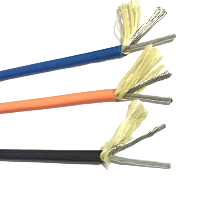
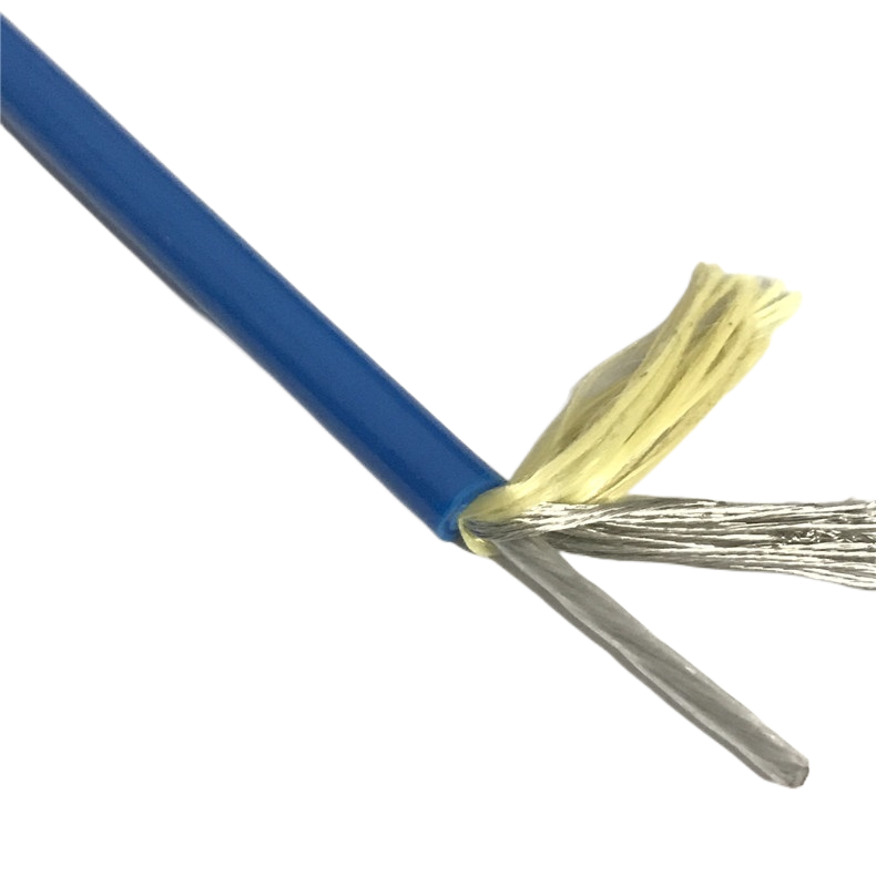
Tensile member — Kevlar (S/D/NB models) |
Kevlar 49 aramid yarns, parallel lay, counter-wound in two layers at equal and opposite helix angles. Tensile rating: 2–8 kN. Elongation at rated load ≤1.5%. |
ASTM D7269; ISO 6892 |
Counter-wound equal-angle layers produce a torque-balanced structure: the torsional moment from the inner layer’s helix is exactly cancelled by the outer layer’s opposing helix. This is the engineering mechanism behind the self-rotation measurement of ≤0.5°/m at rated load. Kevlar 49 is selected over Kevlar 29 for its higher modulus (125 GPa vs 70 GPa) — the lower elongation preserves cable length accuracy in towed sensor arrays where positional accuracy depends on known cable length. |
|
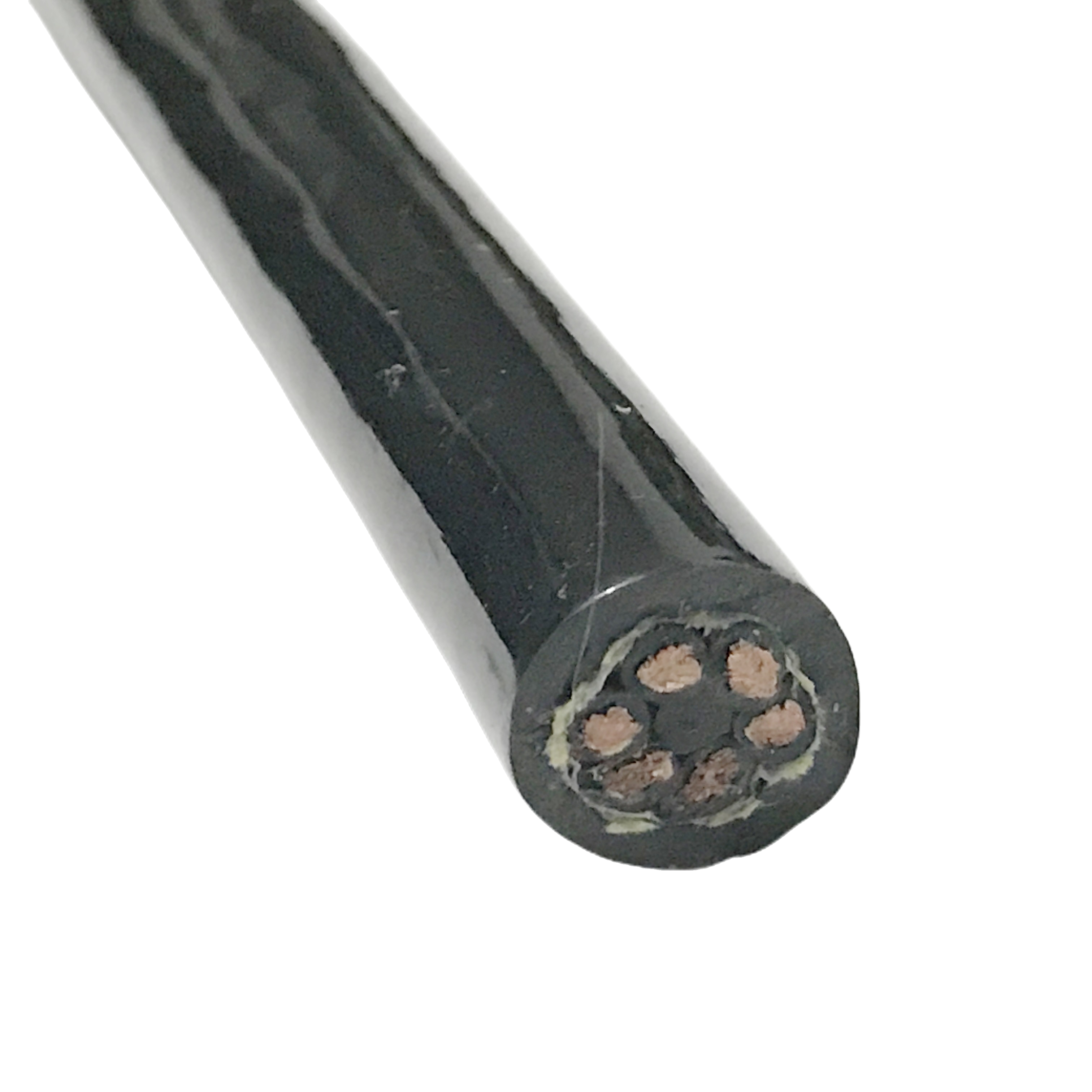
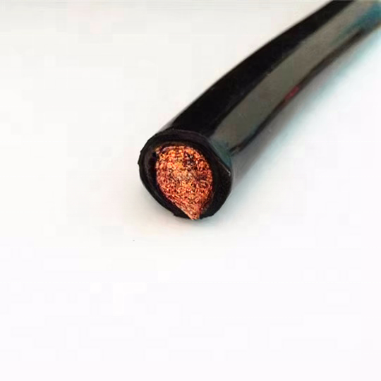
Steel wire armour (A models) |
Galvanised or 316L stainless steel wire, helical lay, single (RST-UTC-A1) or double (RST-UTC-A2) layer. Wire diameter 0.8–1.6 mm. Armour breaking load: 12–20 kN. |
IEC 60502-4; BS 6724 |
Steel armour is specified for applications requiring crush resistance and snag survivability that Kevlar cannot provide — specifically seabed drag operations and trawl-resistant installations. The armour wires are laid in a long helix angle (>55°) relative to the cable axis to maximise crush resistance while minimising the torsional stiffness that would otherwise drive cable self-rotation under load. |
|
Syntactic foam / buoyancy elements (NB model) |
Closed-cell glass microsphere composite foam, density 0.35–0.55 g/cm³, rated to 600 m depth without crushing. Cast around assembled core bundle to achieve target cable density ≈0.98–1.00 g/cm³. |
ASTM D2842; ISO 4590 |
Syntactic foam (glass microballoons in a resin matrix) provides buoyancy that is pressure-stable to rated depth — unlike open-cell foams which compress and lose buoyancy at depth. The target cable density is tuned to ±0.02 g/cm³ of seawater density (1.025 g/cm³) to achieve near-neutral buoyancy. The RST-UTC-NB achieves 0.98 g/cm³, giving a slightly positive net buoyancy in seawater that keeps the cable from sinking and fouling the towed vehicle. |
|
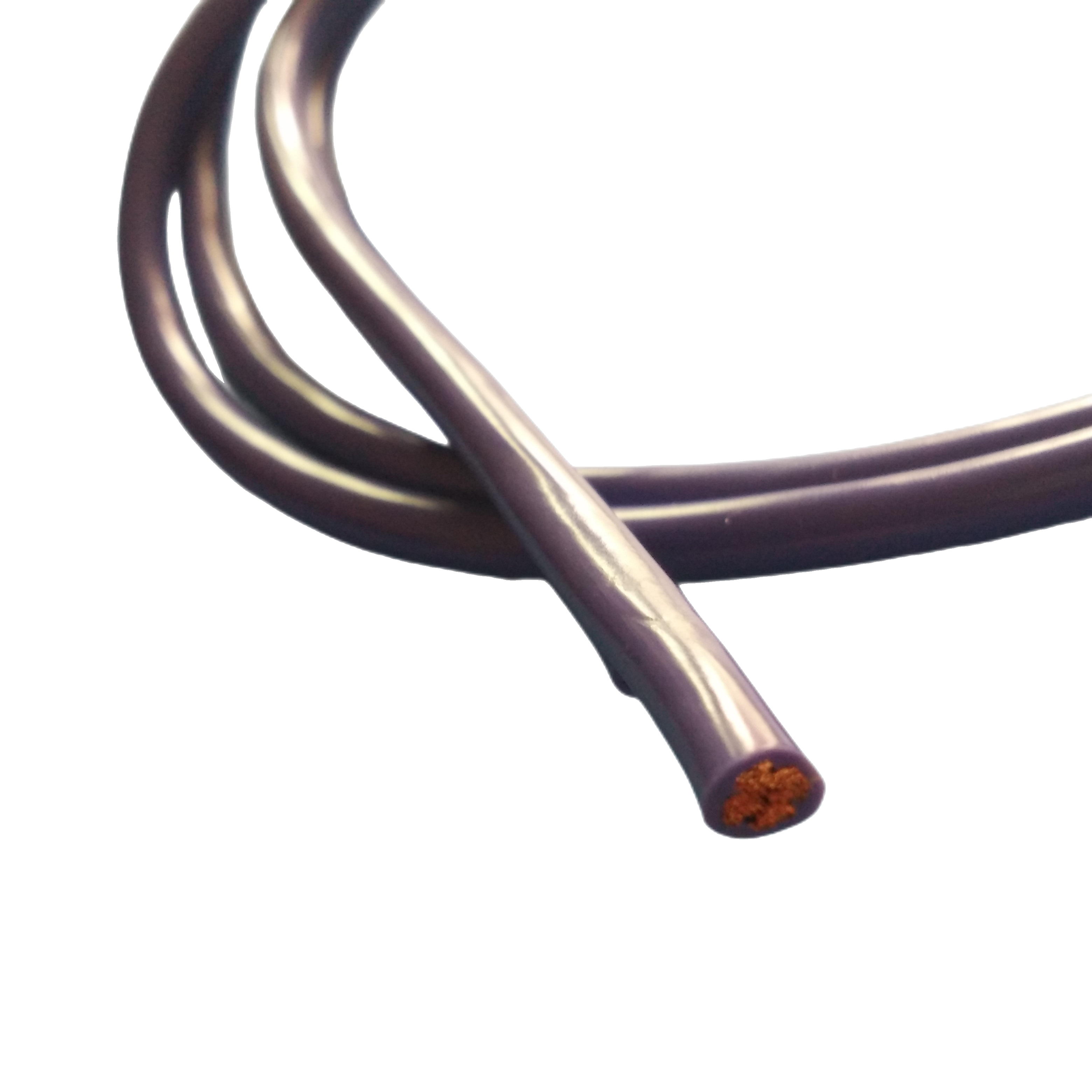
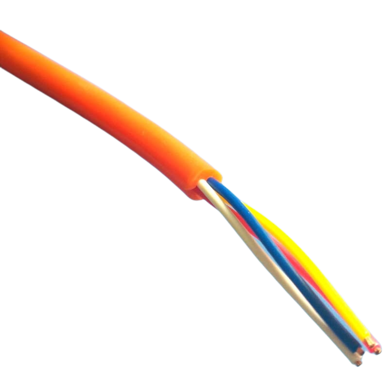
Outer jacket — polyether PUR |
Polyether TPU, Shore A 85±3 (softer than reel grade for improved flexibility at depth). Tensile strength ≥50 MPa. Taber abrasion CS-17, 1 kg: ≥400 cycles. Hydrolysis resistance: confirmed 5,000 h immersion at 23°C, no degradation (ISO 175). |
ISO 37; ISO 9352; ISO 175; ISO 868 |
Polyether PUR is specified over polyester PUR for subsea duty: polyester PUR undergoes hydrolytic degradation in sustained seawater immersion — the ester bonds are cleaved by water molecules, reducing tensile strength by 30–50% within 1–2 years. Polyether PUR has no ester bonds and shows no measurable hydrolytic degradation after 5,000 hours of seawater immersion at 23°C in our test data (ISO 175 method). This is the single most important material selection criterion for subsea cable jackets intended for long-duration deployment. |
Jacket Material Comparison for Subsea Tow Cable
Three jacket materials are specified for subsea cables in commercial and scientific applications. The selection criteria for tow cable differ from fixed-subsea installation cable because tow cables experience repeated mechanical cycling (drum winding, catenary motion) in addition to continuous hydrostatic pressure and seawater immersion.
|
Property |
Polyether PUR (RST-UTC) |
High-Density Polyethylene (HDPE) |
Polychloroprene Rubber (PCP) |
|
Hydrolysis resistance |
Excellent — no ester bonds (tested 5,000 h ISO 175) |
Excellent — no hydrolytic degradation |
Good — slight surface oxidation >2 years |
|
Seawater immersion long-term |
No measurable degradation (polyether base) |
No degradation |
Surface hardening, cracking after 3–5 yr |
|
Abrasion resistance (Taber) |
≥400 cycles CS-17 |
≥200 cycles (unfilled grade) |
150–250 cycles |
|
Flexibility at 0°C seabed |
Excellent (−40°C rated) |
Moderate (becomes rigid at +4°C) |
Good (−30°C rated) |
|
Tensile strength |
≥50 MPa |
22–30 MPa (HDPE100 grade) |
10–18 MPa |
|
Jacket-to-sheath bond in gel-fill construction |
Bond maintained; gel does not migrate into PUR |
Bond unreliable; gel migrates along HDPE surface |
Acceptable |
|
Buoyancy contribution (neutral-buoyancy cable) |
Compatible with syntactic foam co-extrusion |
Not compatible — requires separate foam shell |
Not compatible |
|
UV resistance |
Good (with UV stabiliser package) |
Excellent (HDPE is inherently UV stable) |
Good |
|
Minimum drum winding OD |
10× cable OD (flexible) |
20× cable OD (stiff at low temp) |
12× cable OD |
|
Typical service life, subsea tow |
8–15 years |
12–20 years (if no abrasion) |
5–8 years |
|
Preferred application |
Dynamic tow: ROV, survey, AUV |
Fixed-depth mooring, long-duration static |
Shore approach, surf zone, dynamic with armour |
HDPE is excellent for static long-duration subsea installations but its low-temperature stiffness and higher minimum bend radius make it poorly suited to drum-wound tow cables. RST-UTC specifies polyether PUR for all dynamic tow duty.
Technical Parameters
Electrical
|
Parameter |
Value |
Standard / Reference |
|
Rated voltage (power cores) |
300/500 V (standard); 0.6/1 kV (A2 model) |
IEC 60502-1 |
|
Test voltage (power cores) |
2,000 V AC / 5 min |
IEC 60502-1 Cl.17 |
|
Insulation resistance |
≥500 MΩ·km (all cores, at rated depth) |
IEC 60502-1 Cl.18; tested in pressure vessel |
|
Signal pair characteristic impedance |
120 Ω ± 10 Ω (RS-485); 100 Ω ± 5 Ω (EtherCAT) |
IEC 61156-5 |
|
NEXT (near-end crosstalk) |
≤−40 dB at 10 MHz (screened pairs) |
IEC 61156-5 |
|
Capacitance (screened pairs) |
≤55 nF/km |
IEC 61156-5 |
|
Max. signal conductor resistance |
≤140 Ω/km (0.25 mm²); ≤18.1 Ω/km (1.0 mm²) |
IEC 60228 Cl.5/6 |
Optical (D1, D2, NB, A2 models)
|
Parameter |
Value |
Standard |
|
Fibre type |
ITU-T G.657.A1 single-mode bend-insensitive |
ITU-T G.657.A1 |
|
Attenuation @ 1310 nm |
≤0.35 dB/km (factory); ≤0.50 dB/km at rated depth |
IEC 60793-2-50 |
|
Attenuation @ 1550 nm |
≤0.20 dB/km (factory); ≤0.30 dB/km at rated depth |
IEC 60793-2-50 |
|
Additional attenuation under pressure (1.5× rated depth) |
≤0.10 dB/km (validated in pressure vessel test) |
IEC 60794-1-2 Method E11 |
|
Minimum bend radius (long-term) |
30 mm (G.657.A1 rated) |
IEC 60793-2-50 |
|
Fibre count options |
1, 2, 4, 6, 8, 12 fibres per cable |
Per order |
|
Connector options at factory |
FC/APC, SC/APC, LC/APC (specify at order) |
IEC 61755-3-31 |
Mechanical & Environmental
|
Parameter |
Value / Condition |
Test Standard |
|
Working depth (rated) |
300 m / 1,000 m / 3,000 m / 6,000 m per model |
Pressure vessel test at 1.5× rated depth |
|
Hydrostatic pressure test factor |
1.5× rated working depth (all models) |
IEC 60794-1-2 Method F12B |
|
Tensile rating (Kevlar models) |
2 kN – 8 kN (see model table); tested to 1.5× |
ASTM D7269; load cell tested per drum |
|
Armour breaking load (A models) |
12 kN (A1) / 20 kN (A2); tested to 1.5× |
IEC 60502-4; load cell tested |
|
Self-rotation (Kevlar torque-balanced) |
≤0.5°/m at rated tensile load |
Internal tow-tank validation |
|
Minimum bending radius (dynamic tow) |
10× OD (Kevlar); 15× OD (armoured) |
IEC 60794-1-2 Method E10 |
|
Outer jacket tensile strength |
≥50 MPa |
ISO 37 |
|
Outer jacket elongation at break |
≥350% |
ISO 37 |
|
Jacket abrasion resistance |
≥400 cycles Taber CS-17, 1 kg |
ISO 9352 |
|
Hydrolysis resistance (jacket) |
No degradation after 5,000 h immersion at 23°C seawater |
ISO 175 |
|
Operating temperature |
−40°C to +70°C (surface); 0°C to +4°C (seabed) |
IEC 60811-501 |
|
UV resistance |
1,000 h xenon arc weatherometer, ≤80% tensile retention |
IEC 60811-401 |
|
Longitudinal watertightness |
Gel-fill + SAP tape; no water migration beyond breach point |
IEC 60794-1-2 Method F5B |
|
Flame retardancy (deck-lay sections) |
IEC 60332-1 on request |
IEC 60332-1 |
Towing Cable Sizing Guide
Sizing an underwater towing cable correctly requires four parameters that have no equivalent in any other cable application category. Standard electrical cable sizing tools — which calculate conductor cross-section from current and voltage drop — will give you the right conductor but the wrong tensile member if used alone for tow cable. The four towing-specific inputs below must be resolved first.
|
Input |
What to Determine |
Why It Drives Cable Selection |
|
1. Towing speed & catenary angle |
Max vessel tow speed (knots) and target depth (m). From these, calculate the catenary angle θ at the tow point using a standard catenary model or your tow system software. |
The drag force on the cable itself (not the towed body) is proportional to diameter² and to tow speed². A 2 mm increase in cable OD at 4 knots adds approximately 0.3 kN additional drag per 100 m of cable. This is why OD minimisation matters for deep-tow applications. |
|
2. Total tensile load at top termination |
Sum: (towed body drag at max speed) + (cable drag, calculated by catenary model) + (weight of cable in water at full pay-out, accounting for buoyancy). |
This total load determines the tensile member rating required. Divide by a safety factor of 3 (IOC/UNESCO guidance for scientific tow cable) to get the minimum tensile member rating. A 4 kN load requires a ≥12 kN rated member at SF=3. |
|
3. Working depth |
Maximum operating depth in metres. Apply 1.5× hydrostatic test factor to determine the pressure test requirement. |
Depth determines the jacket compound, water-blocking specification, and whether syntactic foam buoyancy elements are needed. Below 1,000 m, all voids in the cable must be filled — open voids collapse under hydrostatic pressure. |
|
4. Self-rotation requirement |
Does the towed body carry attitude-sensitive sensors (INS, ADCP, magnetometer, streamer hydrophones)? If yes, maximum tolerable rotation rate must be stated. |
If rotation tolerance is <1°/m, specify torque-balanced Kevlar construction (RST-UTC Kevlar models). Armoured cables with single-layer helical wire are inherently non-torque-balanced and will rotate under load. |
Worked Example — Geophysical Survey Tow, 800 m depth, 3.5 kts
|
Given: Survey vessel tow speed 3.5 knots (1.8 m/s). Towed body drag 1.2 kN at 3.5 kts. Cable pay-out 950 m. Target depth 800 m. Attitude-sensitive hydrophone array: max rotation 0.5°/m. 8 signal pairs required. No power to towed body (battery-operated).
Step 1 — Estimate cable drag: Cable drag (simplified) = 0.5 × Cd × ρ × v² × D × L × sinθ For RST-UTC-D1 at OD 18.8 mm: D = 0.0188 m, Cd ≈1.1, ρ = 1025 kg/m³, v = 1.8 m/s, L = 950 m, sinθ ≈0.7 (estimated catenary): Cable drag ≈ 0.5 × 1.1 × 1025 × 3.24 × 0.0188 × 950 × 0.7 ≈ 22,800 N ≈ 22.8 kN — recalculate with proper catenary model; this simplified form overestimates. Using catenary model output (standard practice): cable drag contribution ≈ 1.8 kN at 950 m pay-out, 3.5 kts. Step 2 — Total tensile load: Towed body drag: 1.2 kN Cable drag (catenary model): 1.8 kN Submerged weight of 950 m cable (RST-UTC-D1 near-neutral, net weight in water ≈0.05 kg/m): 950 × 0.05 × 9.81 ≈ 0.47 kN Total tensile load at surface termination: 1.2 + 1.8 + 0.47 = 3.47 kN Step 3 — Tensile member selection: Required tensile rating = 3.47 kN × SF 3.0 = 10.4 kN → RST-UTC-D1 (6 kN Kevlar) is INSUFFICIENT at SF 3. Step up to RST-UTC-A1 (armoured, 12 kN) → SF = 12 / 3.47 = 3.46 ✔ Note: RST-UTC-A1 is armoured (steel wire) — verify rotation requirement before confirming. Step 4 — Self-rotation check: RST-UTC-A1 is single-layer steel armour: NOT torque-balanced. Expected rotation at 3.5 kN: ~2–3°/m — exceeds the 0.5°/m limit. Resolution: RST-UTC-OEM custom — double-layer contra-wound steel armour, torque-balanced, rated 14 kN. Or re-scope tow speed to 2.5 kts to reduce drag and use RST-UTC-D1 (6 kN Kevlar, torque-balanced, rotation ≤0.5°/m) at SF 6/2.1 = 2.9 (acceptable for scientific survey per IOC guidelines).
Recommended cable: RST-UTC-D1 at reduced tow speed (2.5 kts max), or RST-UTC-OEM contra-wound double-armour for 3.5 kts with torque balance. Consult Rousheng engineering team with full catenary model output for binding recommendation. |
FAQ — Questions from Marine Engineers & ROV Operators
Q1: What depth rating actually means — and why the 1.5× test factor matters
A cable rated to 3,000 m means it has been pressure-tested in a hyperbaric chamber to the equivalent of 4,500 m (1.5× the rated depth, per IEC 60794-1-2 Method F12B) and has passed all electrical and optical performance tests during and after that pressure cycle. The 1.5× safety factor is a design margin that covers depth excursions beyond the nominal mission profile, hydrostatic pressure cycling effects on void spaces, and manufacturing tolerances in jacket wall thickness. A cable that has only been tested to 1.0× its rated depth has no safety margin — any deeper-than-planned deployment is an uncontrolled experiment.
Q2: Why does polyester PUR degrade underwater but polyether PUR does not?
Polyester PUR contains ester linkages (–COO–) in its polymer backbone. These bonds are susceptible to hydrolysis: water molecules insert across the bond, breaking it and reducing molecular weight. The degradation accelerates with temperature. At 23°C seawater, a polyester PUR jacket can lose 30–50% of its tensile strength within 18–24 months of continuous immersion — a well-documented failure mode in subsea cable deployments from the 1990s through the 2010s. Polyether PUR replaces the ester linkages with ether linkages (–O–), which are not susceptible to hydrolytic cleavage. Rousheng’s 5,000-hour seawater immersion test (ISO 175) on RST-UTC jacket compound showed no measurable change in tensile strength or elongation. This is not a marketing claim — the test report is available for review by customers qualifying the cable for long-duration deployments.
Q3: What is torque-balanced construction and does my application need it?
A torque-balanced cable is one that does not rotate about its long axis when tensile load is applied. In an unbalanced cable, the helical lay of the tensile member converts tension into a torsional moment, causing the cable to spin. Torque balance is achieved by winding two layers of tensile elements at the same helix angle in opposite directions — the torsional moments cancel. You need torque-balanced cable if your towed body carries any attitude-sensitive sensor whose calibration depends on a known (or zero) cable rotation rate: INS, ADCP, hydrophone arrays, magnetometers, gravimeters. You do not need it for applications where the towed body is mechanically constrained (e.g., a tow sled on a bottom track) or where rotation has no effect on mission outcome.
Q4: Can the cable be terminated at depth — for example, mid-water wet-mate connectors?
Yes, with the appropriate wet-mate connector system. RST-UTC cables are compatible with Subconn, MacArtney, and TE Connectivity SubSea wet-mate connector ranges. Factory termination is available for copper cores; optical fibre terminations require specialist subsea connector assembly which we offer as a service for project quantities. The key requirement for mid-water terminations on tow cable is that the termination must be strain-relieved independently of the conductor connections — the Kevlar or armour tensile member must transfer load through the connector body, not through the copper or fibre connections. Rousheng provides termination design guidance and can supply pre-terminated cable assemblies for qualified projects.
Q5: How do I calculate the voltage drop on a long tow cable supplying a subsea thruster?
Voltage drop calculation for subsea tow cable follows the same formula as any DC or AC cable: VD = 2 × I × R × L (for DC single-phase equivalent). However, three corrections apply that are often missed. First, use the conductor resistance at the actual seabed temperature (typically +2°C to +4°C for deep water): copper resistance decreases by approximately 0.4% per °C, so a conductor rated at 18.1 mΩ/m at 20°C measures approximately 16.7 mΩ/m at 4°C — a 8% reduction that improves VD margin. Second, account for the cable pay-out length, not just the horizontal surface distance — the catenary geometry increases cable length by a factor of 1.05–1.30 depending on depth and tow speed. Third, if the subsea load includes a thruster motor, use 1.5× the rated motor current for cable sizing to account for motor starting current. Our engineering team can run a complete VD calculation if you provide motor nameplate data and tow geometry.
Q6: What is the difference between a tow cable and an umbilical?
The terms are sometimes used interchangeably but they describe different mechanical functions. A towing cable is designed to bear tensile load as its primary mechanical function: the cable is the primary load-bearing element connecting the vessel to the towed body. An umbilical is primarily a services conduit — it may carry some of its own weight in tension, but the ROV or AUV at the end is either neutrally buoyant or supported by the vehicle’s own thrusters. RST-UTC models can serve both functions depending on which model is selected: the Kevlar models (S1, S2, D1, D2, NB) are typically used as umbilicals or light-to-medium tow cables; the armoured models (A1, A2) are the primary load-bearing tow cables for seismic streamers, tow sleds, and heavy intervention systems.
Manufacturer Background — Shanghai Rousheng Subsea Engineering
|
Production & testing Purpose-built subsea cable assembly facility, Shanghai In-house pressure test vessel: to 600 bar (6,000 m equivalent) Optical fibre splicing and test laboratory on-site Kevlar tensile member assembly and load testing to 1.5× rated 100% HiPot and insulation resistance test per drum OTDR trace supplied with every optical cable drum |
Approvals & documentation ISO 9001:2015 quality management system CE marking — LVD Directive 2014/35/EU RoHS 2 / REACH SVHC compliance DNV / Bureau Veritas type approval (on request) CNAS-accredited lab test reports available Pressure test certificates issued per drum, NIST-traceable |
Rousheng’s subsea cable engineering team has provided written failure analysis on subsea tow cable failures submitted by survey contractors, naval operators, and oceanographic institutions. In each case we identify the failure mode from physical examination and test data, and document the specification change that would have prevented it. This service is available to all customers considering RST-UTC cables for new projects — we believe the fastest way to earn a supply relationship is to solve an existing problem, not to recite a product brochure.
Request a Quote, Sample, or Technical Review
|
Contact Rousheng Email: Jerry@rstlkable.com Phone: +86-021-50759965 Mobile: +86-13482197396 Address: No. 2591 Fengzhe Road, Fengxian District, Shanghai Quote within 24 hr. Pressure test certificate and OTDR trace included with every order. |
Include in your enquiry 1. Target operating depth (m) 2. Max tow speed (knots) and cable pay-out length (m) 3. Towed body drag load (kN) if known 4. Power requirement at towed body (V, A) 5. Signal types required (RS-485, EtherCAT, fibre, etc.) 6. Self-rotation tolerance (°/m), if applicable We return a tensile member recommendation, OD estimate, and VD calculation with every enquiry. |