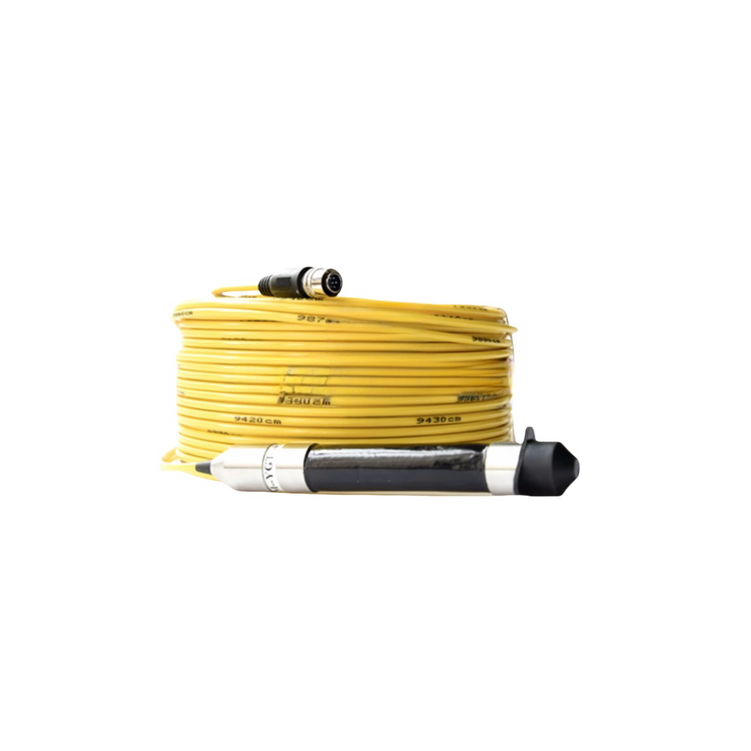
Underwater Fiber Optic Cable | High-Performance Subsea Data Transmission for Offshore & ROV Systems
The RST-FOC Series Underwater Fiber Optic Cable delivers stable, high-speed data transmission for ROV umbilicals, offshore monitoring, seismic systems, and offshore wind networks.
Rated from 300 m to 6,000 m with 2–96 fibres, it offers Kevlar-reinforced and double-armoured options for both lightweight and heavy-duty subsea applications.
Using G.657.A1 bend-insensitive fibre in a gel-filled loose-tube design, it ensures <0.08 dB/km additional attenuation under pressure. Dual water-blocking limits seawater ingress to <0.5 m.
The polyether TPU jacket provides long-term seawater resistance. Certified to ISO 9001:2015, compliant with CE, RoHS, REACH, with optional DNV/BV approval. Supplied with OTDR and pressure test reports.
Underwater Fiber Optic Cable | High-Performance Subsea Data Transmission for Offshore & ROV Systems
Product Series: RST-FOC │ Category: Subsea Fiber Optic Cables │ Reviewed by: Rousheng Optical Engineering Team
|
Max depth rating 6,000 m Hyperbaric tested at 1.5× |
Min attenuation 0.18 dB/km SM at 1,550 nm, factory-measured |
Max fibre count 96 fibres Single jacket, custom |
|
Tensile rating Up to 20 kN Double-armoured models |
Water-block method Gel + SAP Migration ≤0.5 m from breach |
OTDR trace Included Per fibre, per drum, 2 wavelengths |
Underwater fiber optic cable is the only viable data transmission medium for the signal bandwidths, latencies, and distances demanded by modern subsea systems — from real-time 4K video feeds on deep-intervention ROVs to terabit-per-second data streams from offshore seismic arrays. Copper conductor cables, regardless of their signal-pair count, hit a hard physics limit at long subsea runs: the combination of resistive loss, capacitive attenuation, and propagation delay makes high-bandwidth, low-latency data transmission over distances beyond a few hundred metres impractical without active repeaters. Optical fibre has no such limit within the distances relevant to offshore and marine applications.
The engineering challenge in subsea fibre deployment is not the fibre itself — ITU-T G.657.A1 bend-insensitive single-mode fibre, used in the RST-FOC series, is a mature, high-reliability component with a 25-year design life on land networks. The challenge is protecting that fibre from the mechanical and chemical environment of the ocean: hydrostatic pressure that increases at 0.1 MPa per 10 m, seawater that hydrolyses polyester-based jacket materials, tidal and dynamic loading that micro-bends fibres in incorrectly protected constructions, and installation stresses that permanently degrade fibres in cables designed without adequate crush resistance.
This page describes how each element of the RST-FOC construction addresses a specific environmental threat, provides a practical link-budget calculation guide for subsea fibre runs, and documents five field deployments in which the cable’s optical performance specifications were verified under operational conditions.
Page Contents
- Why Fiber Optic — The Physics Case Against Copper at Depth
- Model Range: RST-FOC Specifications at a Glance
- Construction Engineering — Layer by Layer with Failure Prevention Logic
- Protocol Compatibility Matrix
- Subsea Link Budget Calculator — Worked Example
- Technical Parameters (Optical, Mechanical, Environmental)
- Field Deployment References
- Installation Guide: Avoiding Permanent Attenuation Events
- FAQ — Fiber Optic Engineers & ROV System Integrators
- Manufacturer Credentials & Documentation
- Request a Quote
Why Fiber Optic — The Physics Case Against Copper at Subsea Distances
The decision between copper and fibre for a subsea data link is ultimately a physics decision, not a preference. The table below shows the transmission limits of copper signal cable versus single-mode fibre at the data rates relevant to ROV video, sensor telemetry, and offshore SCADA.
|
Metric |
Copper (Cat 5e screened pair) |
Copper (RS-485, 120Ω pair) |
SM Fiber G.657.A1 (RST-FOC) |
|
Max reliable run length at 1 Gbit/s (1000BASE-T) |
100 m (IEEE 802.3 limit, no extension) |
Not applicable (RS-485 max 10 Mbit/s) |
>80 km (loss-limited, not length-limited) |
|
Max reliable run length at 100 Mbit/s |
100 m |
Not applicable |
>80 km |
|
Max reliable run length at 9,600 baud (RS-485 Modbus) |
1,200 m (EIA-485, with termination) |
4,000 m (with line driver) |
>50 km with SFP media converter |
|
Attenuation at 100 m |
~24 dB (Cat 5e at 100 MHz) |
~1 dB at 1 MHz |
~0.02 dB at 1,550 nm |
|
Latency per km |
~5 μs (copper propagation) |
~5 μs |
~4.9 μs (fiber propagation, 0.68c) |
|
Susceptibility to EM interference |
High — seawater is a conductor; EMI from thrusters |
Moderate with shielding |
Zero — photons are not affected by EM fields |
|
Galvanic corrosion risk |
High at any jacket breach in seawater |
High |
None — glass fiber is electrically inert |
|
Bandwidth scalability |
Fixed by copper physics |
Fixed |
Upgradeable by changing transceivers only |
|
Design decision point: If any of the following apply to your system, fiber optic cable is the only viable medium: (1) data rate requirement exceeds 10 Mbit/s at any run length; (2) run length exceeds 500 m at any data rate; (3) the cable passes near thruster motors, power cables, or other EMI sources; (4) the deployment duration exceeds 2 years in seawater (copper conductor insulation degrades faster than fiber in sustained seawater exposure). If none apply, a copper data cable may be adequate — contact our team for an honest assessment before specifying fiber. |
RST-FOC Series — Model Specifications
|
Model |
Fibre Type |
Fibre Count |
Depth Rating |
Tensile Member |
Armour |
OD |
Primary Application |
|
RST-FOC-S-2SM |
SM G.657.A1 |
2 |
300 m |
Kevlar 1 kN |
None |
8.2 mm |
Short ROV umbilical, shallow instrument |
|
RST-FOC-S-4SM |
SM G.657.A1 |
4 |
500 m |
Kevlar 2 kN |
None |
9.8 mm |
Offshore platform sensor, 4-channel simplex |
|
RST-FOC-M-8SM |
SM G.657.A1 |
8 |
1,000 m |
Kevlar 4 kN |
None |
12.4 mm |
ROV HD video + telemetry, offshore mooring |
|
RST-FOC-M-12SM |
SM G.657.A1 |
12 |
2,000 m |
Kevlar 5 kN |
None |
14.0 mm |
Subsea observatory, multi-instrument node |
|
RST-FOC-D-24SM |
SM G.657.A1 |
24 |
3,000 m |
Kevlar 6 kN |
None |
18.6 mm |
Seismic data acquisition, deep survey |
|
RST-FOC-D-48SM |
SM G.657.A1 |
48 |
4,000 m |
Kevlar 8 kN |
None |
24.2 mm |
Dense sensor array, oceanographic backbone |
|
RST-FOC-A-8SM |
SM G.657.A1 |
8 |
1,000 m |
SS wire 8 kN |
Single SS |
18.0 mm |
Shore approach, surf zone, seabed drag risk |
|
RST-FOC-A-24SM |
SM G.657.A1 |
24 |
3,000 m |
SS wire 14 kN |
Double SS |
25.5 mm |
Offshore wind SCADA, heavy subsea trunk |
|
RST-FOC-H-4SM |
SM G.657.A1 |
4 |
6,000 m |
Kevlar 6 kN + steel wire |
Double SS |
22.8 mm |
Hadal ROV, full ocean depth research |
|
RST-FOC-MM-8 |
MM OM4 50/125μm |
8 |
200 m |
Kevlar 2 kN |
None |
11.6 mm |
Diver comms, ROV short-range high-BW video |
|
RST-FOC-OEM |
SM/MM/DSF custom |
1–96 |
Per spec |
Per spec |
Per spec |
Per spec |
Naval, offshore, research custom projects |
SM = ITU-T G.657.A1 single-mode. MM OM4 = IEC 60793-2-10 50/125μm. DSF = dispersion-shifted fiber (ITU-T G.653, for coherent systems). All models gel-filled loose tube. Depth ratings at 1.5× hydrostatic test factor. OTDR trace (1310+1550 nm SM, 850 nm MM) included with every drum.
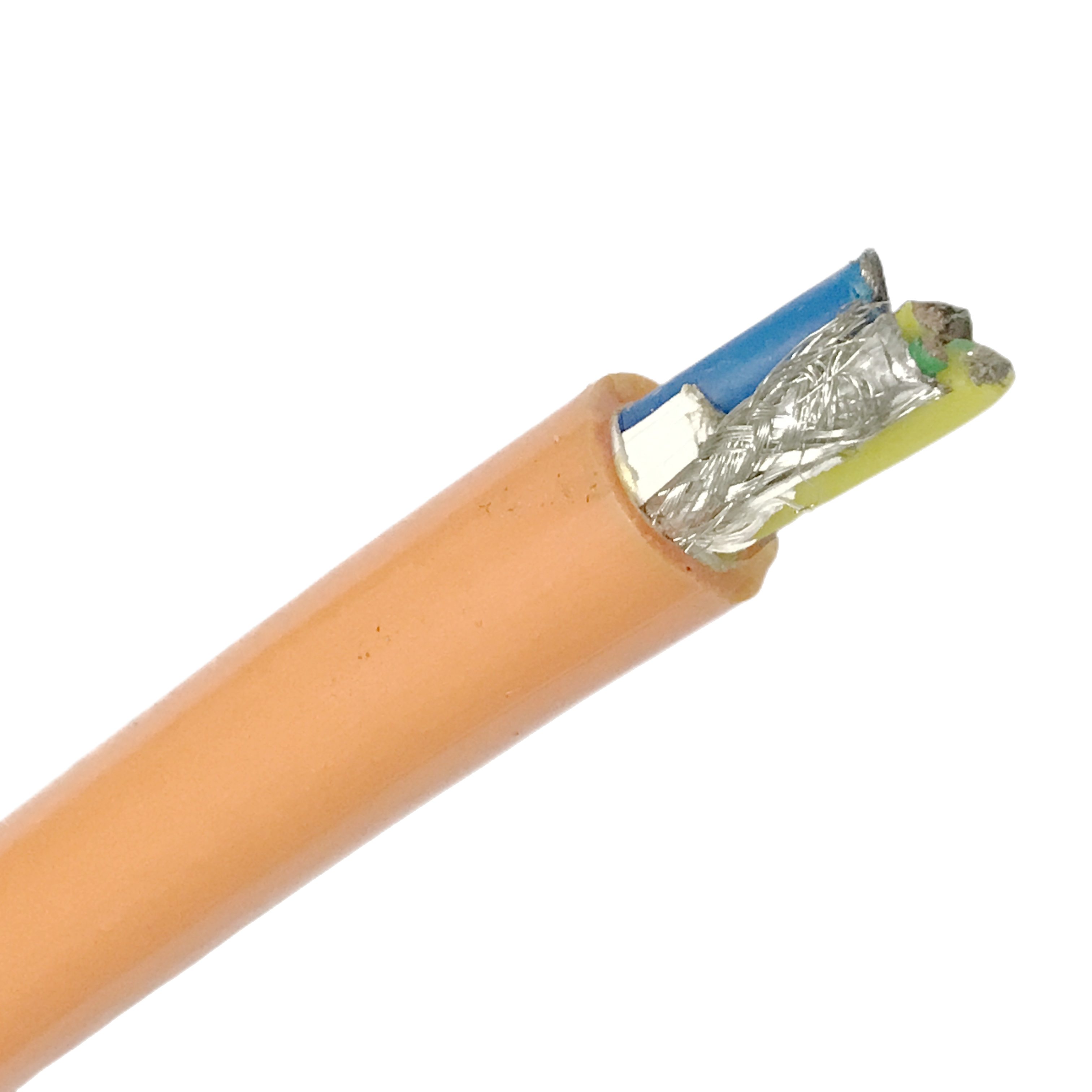
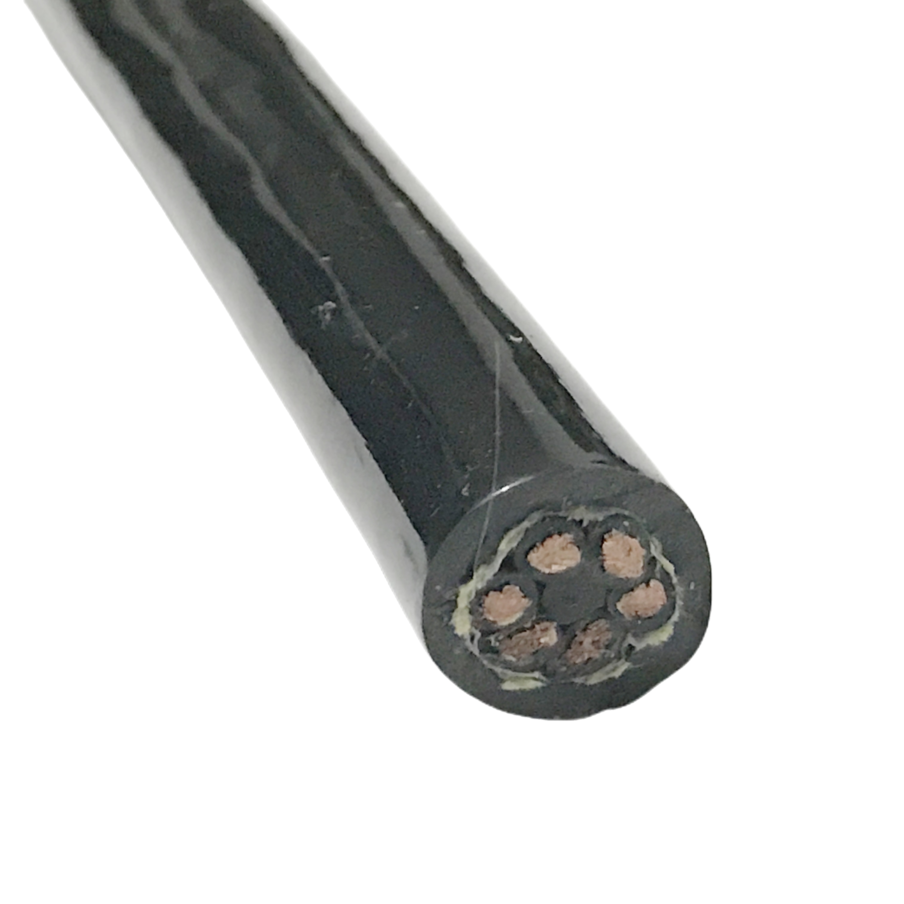
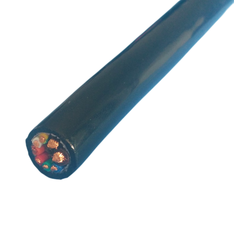
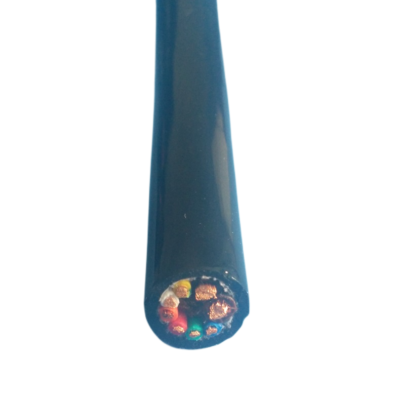
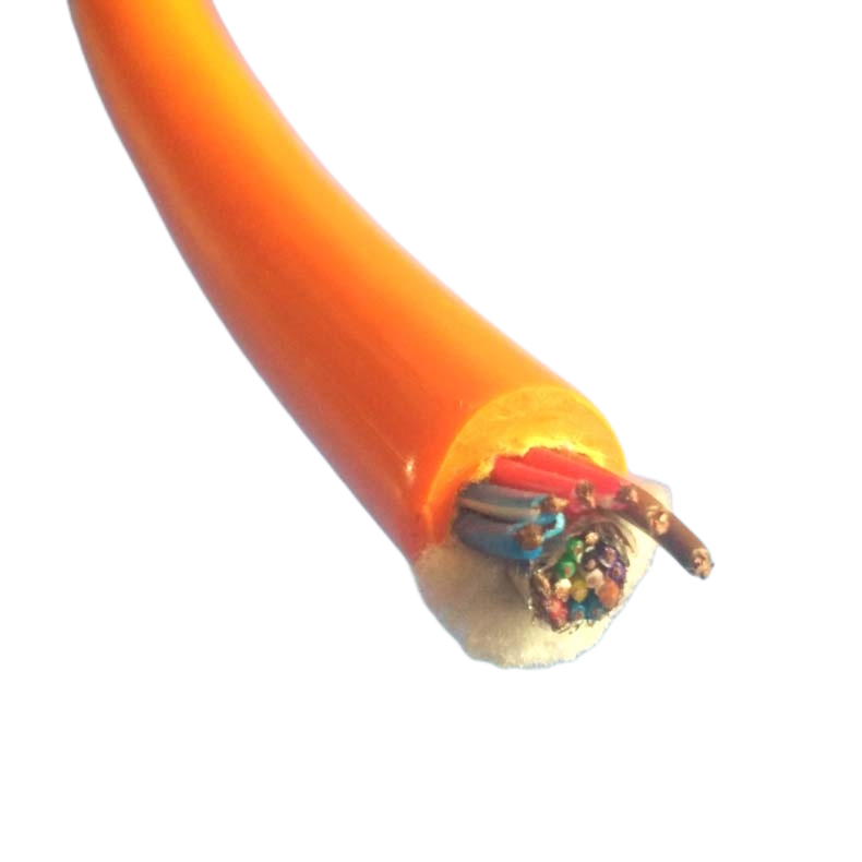
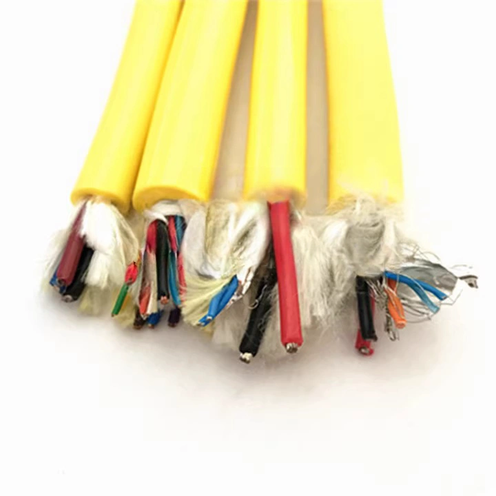
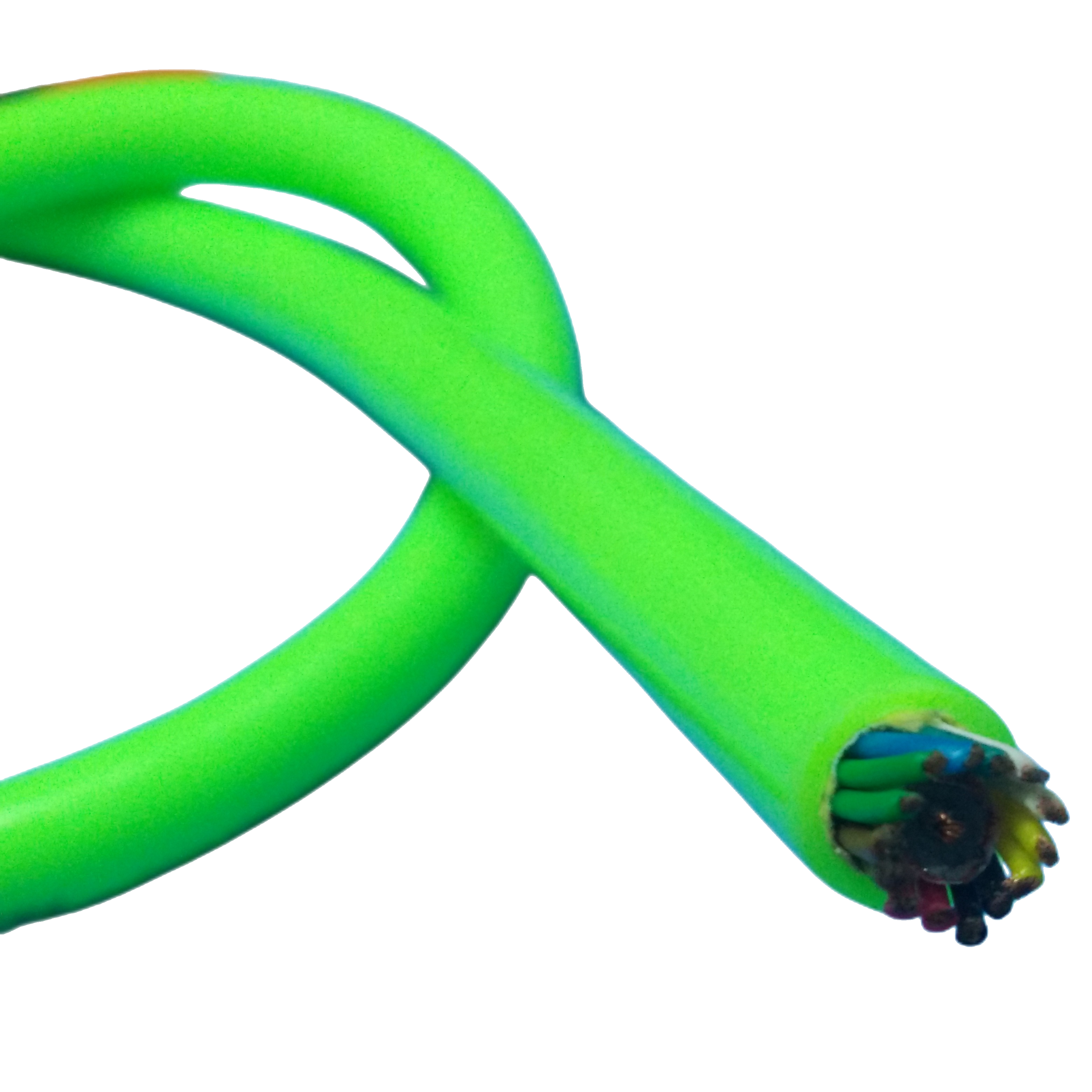
Construction — Layer-by-Layer Failure Prevention
Each structural layer in the RST-FOC construction exists to neutralise a specific failure mechanism. Understanding the prevention logic behind each layer makes it possible to evaluate whether a given cable is actually engineered for subsea duty or simply adapted from a terrestrial design with a different outer jacket.
|
Layer |
Material & Spec |
What Fails Without This Design Choice |
RST-FOC Prevention Mechanism |
|
Optical fibre |
ITU-T G.657.A1 SM bend-insensitive, or IEC 60793-2-10 MM OM4. Dual-coat primary buffer: UV-acrylate inner + UV-acrylate outer, 250 μm total. Curl radius: ≥7.5 mm without measurable additional attenuation (G.657.A1). |
Standard G.652.D fibre develops measurable attenuation increase (macrobend loss) when bent tighter than 30 mm radius during installation, drum winding, or dynamic cable motion. In a subsea umbilical that coils at the ROV base, G.652.D fibre routinely shows 0.5–1.5 dB additional loss per coil. |
G.657.A1 bend-insensitive fibre reduces macrobend sensitivity by >10 dB at 15 mm radius versus G.652.D. This is the minimum fibre specification for any ROV umbilical or dynamic subsea cable. |
|
Gel-filled loose tube |
PBT (polybutylene terephthalate) loose tube, 2.0 mm ID, 2.8 mm OD. 2–12 fibres per tube (excess fibre length: +0.05% to +0.25%). Tube filled with thixotropic petroleum gel, non-migrating from −40°C to +70°C. |
Tight-buffered fibre construction bonds the secondary buffer directly to the fibre. Hydrostatic pressure is transmitted through the stiff buffer as a bending moment. At 500 m depth (5 MPa), tight-buffered fibres show measurable micro-bending attenuation. At 2,000 m (20 MPa), the micro-bending penalty can exceed the system power budget. |
Loose tube construction leaves the fibre free to move within the gel-filled tube. Pressure is transmitted as isotropic gel pressure with no bending moment. RST-FOC validates <0.08 dB/km additional attenuation at 1.5× rated hydrostatic pressure in hyperbaric chamber testing. Excess fibre length (+0.05–0.25%) accommodates cable elongation under tensile load without fibre strain. |
|
Water-blocking gel fill (interstice) |
Non-migrating petroleum water-blocking gel fills all interstices between tubes and strength members. Applied under controlled temperature and vacuum to ensure complete void elimination. |
Air voids in the cable core create two failure modes: (1) at depth, air compresses and the void collapses, deforming the fibre tube; (2) at any jacket breach, the void acts as a capillary channel, drawing seawater inward. A 100 m section of cable with a single 5 mm jacket cut can completely flood within 45 minutes if no longitudinal water-blocking is present. |
Complete void fill eliminates both failure modes. The gel is formulated to remain viscous (not set solid) from −40°C to +70°C, covering the full range from Arctic seabed temperature to tropical deck storage. Viscosity is calibrated to allow fibres to move freely within tubes (loose-tube function preserved) while preventing gel migration under gravity. |
|
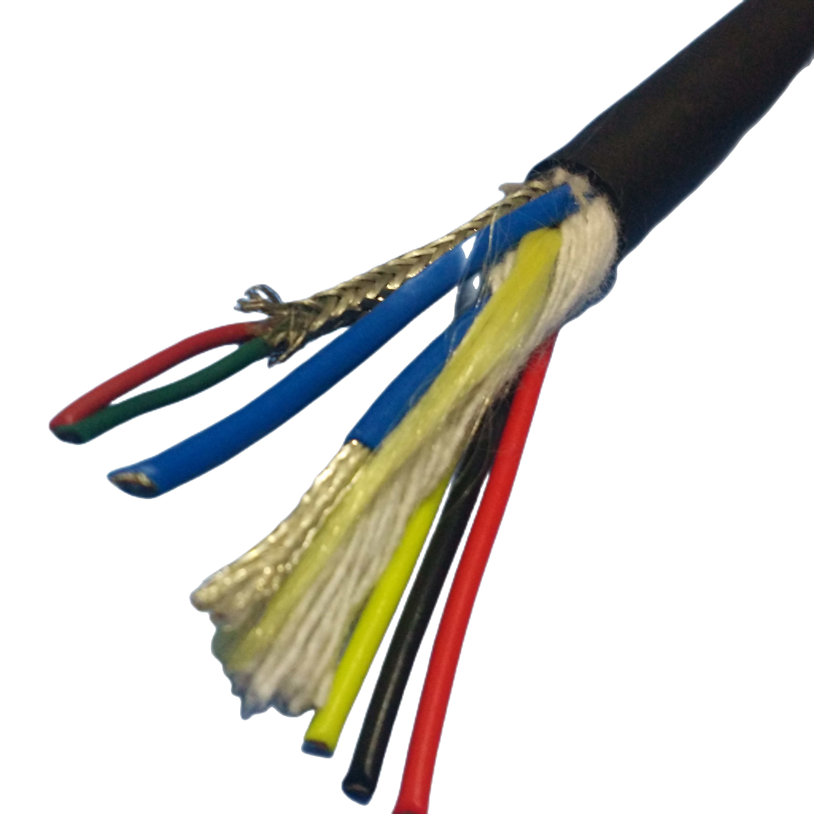
SAP water-blocking tape |
Super-absorbent polymer (SAP) coated non-woven tape, wound over assembled tube bundle. SAP absorption capacity: ≥400× by weight in seawater. Swelling speed: full gel formation within 30 seconds of seawater contact. |
If gel fill alone is used without a secondary barrier, a jacket breach in dynamic service (where the cable flexes and the breach may be repeatedly opened and closed) allows gel to be expelled at the breach point over time. Once gel is lost from a section, longitudinal water migration resumes. |
SAP tape forms a physical gel plug at the breach point, independent of the petroleum gel fill. The two systems are redundant: either alone limits migration to <0.5 m; both together guarantee containment even if one system is compromised. This dual-barrier specification is validated per IEC 60794-1-2 Method F5B. |
|
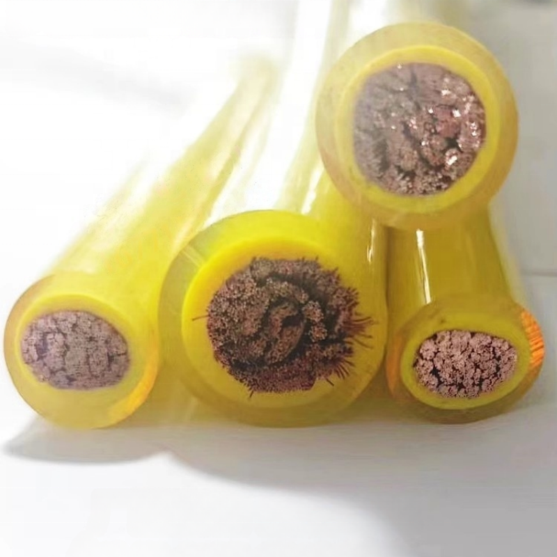
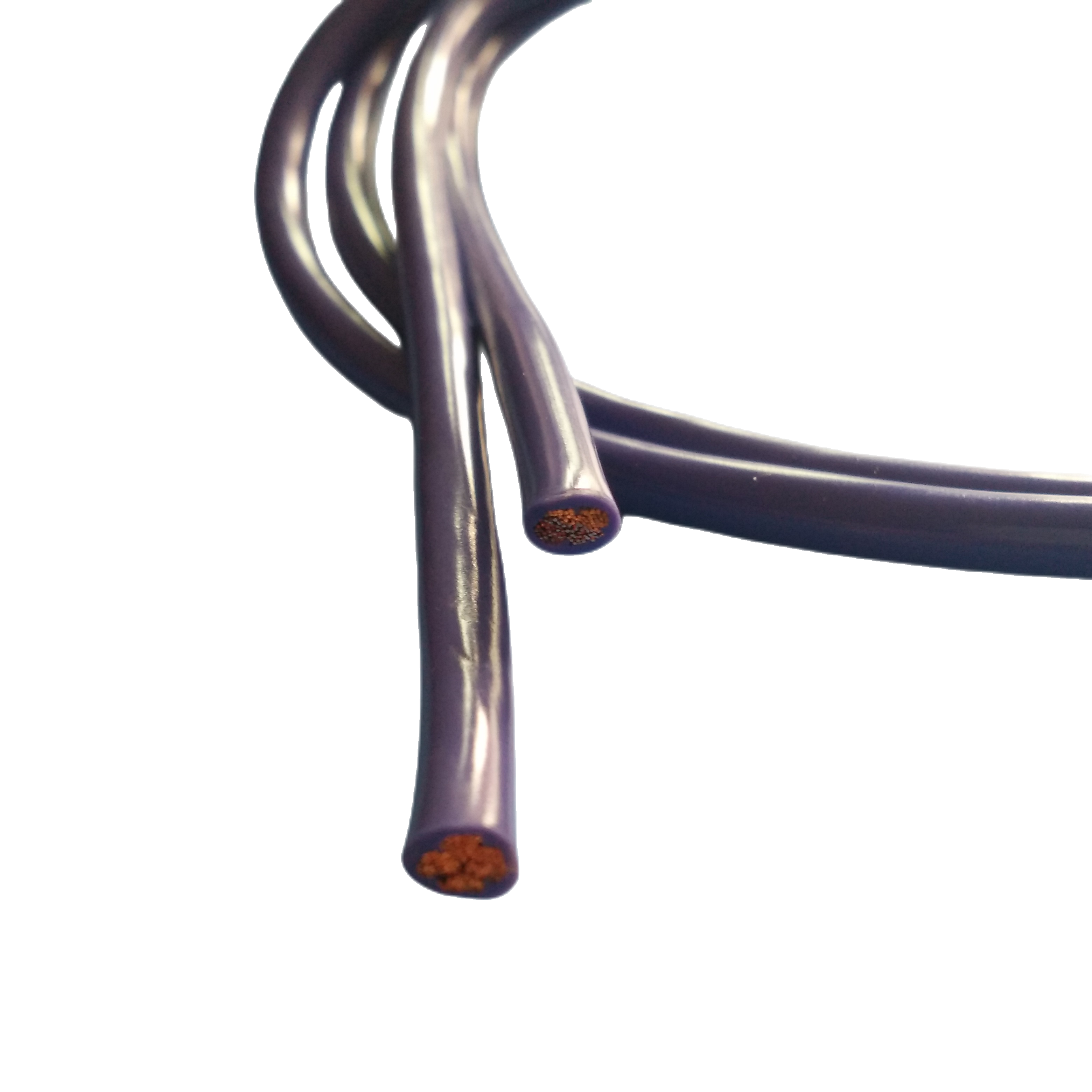
Central strength member (non-armoured models) |
Glass-fibre reinforced plastic (GRP) rod, 2.5–4.0 mm diameter. Modulus: 40–60 GPa. Low CTE matched to fibre elements. Or: Kevlar 49 yarn bundle, parallel lay. |
Without a central strength member, the cable buckles under compressive load (as occurs when a taut cable is suddenly slackened and the catenary collapses). Fibre tubes kink at the buckle point, causing permanent high-attenuation events. |
GRP rod provides column strength to resist buckling under compressive excursions. Kevlar yarn bundle provides tensile strength without column strength — specified when the deployment geometry does not produce compressive loading (e.g., vertical drops from surface to seabed instrument). Model selection determines which is appropriate. |
|
Kevlar tensile member (Kevlar models) |
Kevlar 49 parallel-lay yarns, counter-wound in two equal and opposite helix layers for torque balance. Rating: 1–8 kN. Elongation at rated load ≤1.5%. |
A fiber-only cable with no tensile member relies on the outer jacket and fibre tubes to carry tensile load during installation and in dynamic service. At load levels beyond ~200 N, fibre strain increases and excess fibre length is consumed — the fibre becomes taut within its tube and begins to experience micro-bending from tube wall contact. |
Kevlar carries the full tensile load. Excess fibre length (+0.05–0.25%) is preserved because the fibre experiences zero tensile strain at rated cable load. Load-tested to 1.5× rated load before shipment; certificate included. |
|
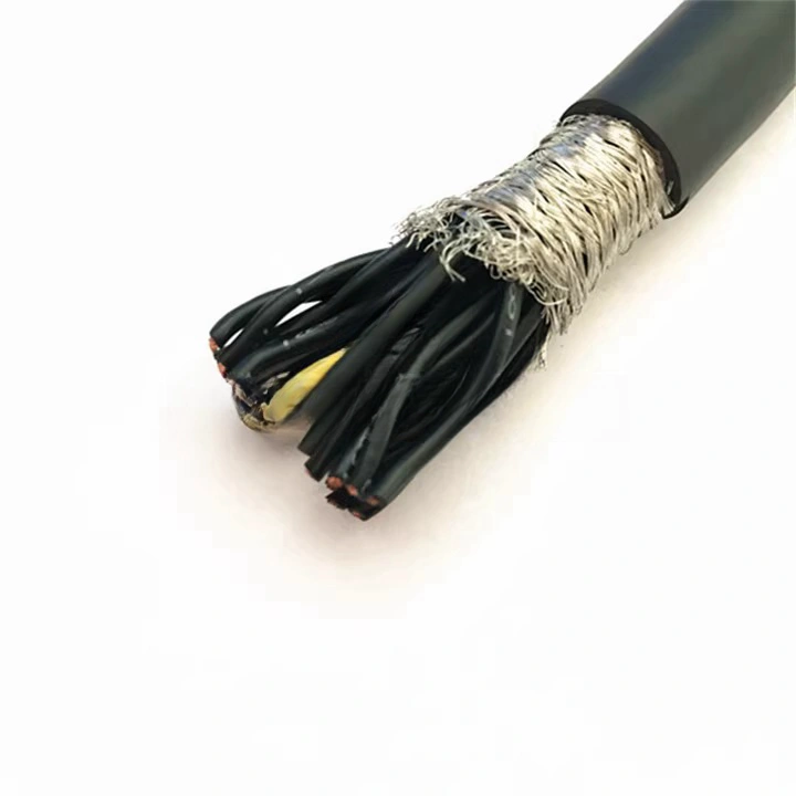
Stainless steel wire armour (A and H models) |
316L SS wire, 0.9–1.6 mm diameter, helical lay 55°. Single layer (RST-FOC-A-8SM): 8 kN. Double contra-wound (RST-FOC-A-24SM, RST-FOC-H): 14–20 kN. Bedding layer: polyester tape over fibre bundle before armour. |
In surf zone and shore approach installations, unarmoured cables are vulnerable to rock abrasion, anchor impact, and trawl-gear contact. A single penetration of the outer jacket on an unarmoured cable at 10 m depth in a tidal zone leads to seawater flooding of the cable run within hours. |
Steel armour provides crush resistance (radial) and tensile strength independent of the Kevlar. 316L SS is specified over galvanised carbon steel to eliminate the galvanic corrosion that occurs when galvanised (zinc-coated) steel contacts copper conductors (if present) or the stainless infrastructure (rig legs, J-tubes) in seawater electrolyte. |
|
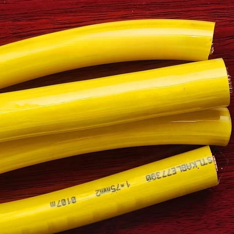
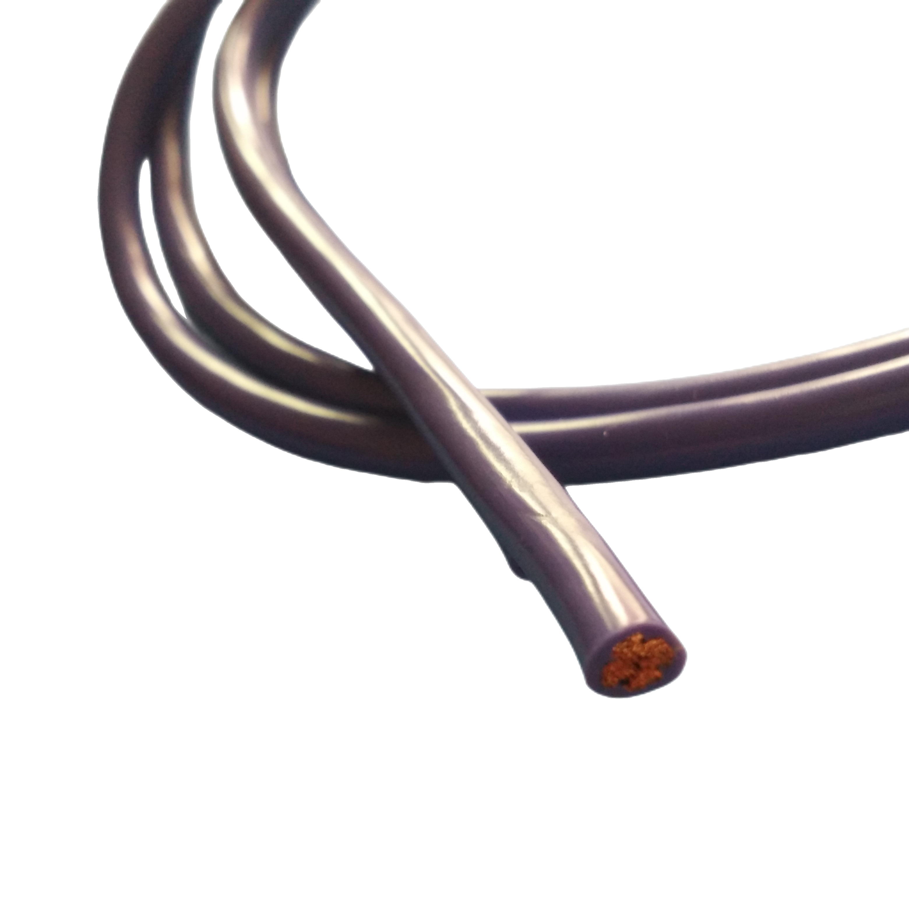
Outer jacket — polyether PUR |
Polyether TPU, Shore A 82±3. Tensile: ≥48 MPa. Elongation: ≥380%. Taber CS-17 1 kg: ≥350 cycles. Seawater hydrolysis: <1% tensile change after 5,000 h at 23°C (ISO 175). UV: 1,000 h xenon arc, ≤80% tensile retention. |
Polyester PUR jackets undergo hydrolytic degradation in sustained seawater immersion: ester bonds are cleaved by water molecules, reducing tensile strength progressively over 12–24 months. In an ROV umbilical on a working vessel operating 300 days/year, a polyester PUR jacket reaches functional failure within 2–3 years. Field evidence of this failure mode has been reported in multiple ROV operator maintenance logs. |
Polyether PUR has no ester bonds and is not susceptible to hydrolysis. The 5,000 h ISO 175 test data (available on request) confirms <1% change in tensile strength and elongation after continuous seawater immersion at 23°C — equivalent to approximately 7 years of subsea deployment based on accelerated aging correlation. |
Protocol Compatibility Matrix
The RST-FOC series serves as the physical layer for a range of data protocols used in offshore and subsea systems. The table below maps each protocol to the minimum fibre specification, maximum reliable run length, and the RST-FOC model that supports it.
|
Protocol / Standard |
Min Fibre Type |
Max Run Length |
Wavelength |
Bandwidth |
RST-FOC Model(s) |
|
1000BASE-SX (Gigabit Ethernet, multimode) |
MM OM4 50/125μm |
550 m (IEEE 802.3z) |
850 nm |
1,000 Mbit/s |
RST-FOC-MM-8 |
|
1000BASE-LX (Gigabit Ethernet, SM) |
SM G.657.A1 |
5,000 m (IEEE 802.3z) |
1,310 nm |
1,000 Mbit/s |
RST-FOC-M-8SM and above |
|
10GBASE-LR (10 Gbit/s Ethernet, SM) |
SM G.657.A1 |
10,000 m (IEEE 802.3ae) |
1,310 nm |
10,000 Mbit/s |
RST-FOC-M-8SM and above |
|
EtherCAT (IEC 61158 Type 12) |
SM G.657.A1 |
Unrestricted (EtherCAT spec) |
1,310 nm |
100 Mbit/s physical |
RST-FOC-S-4SM and above |
|
PROFINET IRT (Class 3) |
SM G.657.A1 |
Up to 3,000 m per segment |
1,310 nm |
100 Mbit/s |
RST-FOC-M-8SM |
|
SMPTE 2110 (HD-SDI over fiber, 3G-SDI) |
SM G.657.A1 |
Up to 40 km |
1,310 / 1,550 nm |
3,000 Mbit/s (3G-SDI) |
RST-FOC-M-8SM and above |
|
4K UHD video (SFP CWDM mux, 4 channels) |
SM G.657.A1 |
Up to 80 km per mux span |
CWDM 1,470–1,610 nm |
4×3,000 Mbit/s |
RST-FOC-D-24SM (8 fibres min) |
|
Hydrophone OFDM telemetry (seismic array) |
SM G.657.A1 |
Segment per array design |
1,550 nm |
Protocol-specific |
RST-FOC-D-24SM or D-48SM |
|
OTDR (cable health monitoring) |
SM G.657.A1 |
Up to cable rated length |
1,310 + 1,550 nm |
Single-ended reflectometry |
Any SM model — spare fibre recommended |
Run lengths are at protocol specification limits, not RST-FOC cable limits. Fiber attenuation is the practical limit for SM fiber: at 0.20 dB/km and 1,550 nm, a 28 dB power budget gives a 140 km run before amplification. SFP/SFP+ transceiver selection must be confirmed by the integrator for the specific protocol and fiber count.
Subsea Fiber Link Budget — Worked Example
A fiber optic link budget accounts for all sources of signal loss between the transmitter and receiver. The link must show positive margin: if total loss exceeds the system’s power budget, the link will not work reliably. For subsea fiber cables, the budget must also include losses that do not appear in terrestrial fiber links: additional attenuation under hydrostatic pressure, additional loss at dynamic bend points in the cable route, and connector losses at subsea wet-mate penetrators.
Scenario: ROV 4K Video Link, 800 m Depth, 950 m Cable Length
|
System parameters: Transceiver: 1000BASE-LX SFP, TX power −0 dBm, RX sensitivity −23 dBm. Power budget: 23 dB. Fiber: RST-FOC-M-8SM (SM G.657.A1). Cable length: 950 m. Working depth: 800 m. Wet-mate connectors: 2 (one topside, one at ROV). Fusion splices: 2 (drum-end factory splices to pigtails). Dynamic bending: estimated 1,500 cycles/year at ROV coiling radius 0.15 m. |
|
Loss Component |
Loss per Unit |
Quantity |
Sub-total (dB) |
Notes |
|
Fiber attenuation @ 1,310 nm |
0.36 dB/km |
0.95 km |
0.34 dB |
Factory OTDR value |
|
Additional attenuation at 800 m depth (1.5× = 1,200 m test) |
0.08 dB/km |
0.95 km |
0.076 dB |
Hyperbaric test data, RST-FOC-M series |
|
Fusion splice loss (pigtail to cable) |
0.10 dB |
2 splices |
0.20 dB |
IEC 61300-3-4 measured |
|
Wet-mate connector (topside) |
0.50 dB |
1 |
0.50 dB |
Subconn MCBH series, IPC rated |
|
Wet-mate connector (ROV end) |
0.50 dB |
1 |
0.50 dB |
Same type; cleaned per IEC 61300-3-35 |
|
Dynamic bending additional loss |
0.02 dB/km per 1,000 cycles |
0.95 km × 1.5k cycles/yr × 5 yr |
0.14 dB |
RST-FOC in-composite bend test data |
|
Cable aging / margin allowance |
0.05 dB/km (5-year estimate) |
0.95 km |
0.05 dB |
Conservative aging allowance |
|
TOTAL INSERTION LOSS |
|
|
1.81 dB |
|
|
SYSTEM POWER BUDGET |
|
|
23.00 dB |
TX 0 dBm, RX sens. −23 dBm |
|
LINK MARGIN |
|
|
+21.19 dB |
Positive margin: link is reliable |
|
Result: The 21.19 dB link margin far exceeds the minimum recommended margin of 3 dB (IEC 61290-10-1 guidance for installed systems). This margin can accommodate an additional 12 wet-mate connector pairs, or a total fiber run of approximately 59 km at 0.36 dB/km, before the link budget is exhausted. For this application, RST-FOC-M-8SM is substantially over-specified on optical budget — the driver for selection is the mechanical depth rating and dynamic flex performance, not the optical budget. Practical note: Always design to a minimum 3 dB end-of-life margin for unmanned, un-maintained subsea links. For links with access for periodic connector cleaning, 1 dB margin is sometimes accepted on short runs. Rousheng’s engineering team can provide a full link budget analysis for any RST-FOC configuration on request. |
Technical Parameters
Optical — Single-Mode (SM G.657.A1)
|
Parameter |
Specification |
Test Standard |
|
Attenuation @ 1,310 nm |
≤0.36 dB/km |
IEC 60793-2-50 (factory) |
|
Attenuation @ 1,550 nm |
≤0.20 dB/km |
IEC 60793-2-50 (factory) |
|
Attenuation @ 1,625 nm (L-band) |
≤0.23 dB/km |
IEC 60793-2-50 |
|
Additional attenuation at 1.5× rated depth |
≤0.08 dB/km @ 1,550 nm |
IEC 60794-1-2 Method F12B (hyperbaric) |
|
Additional attenuation: 1,000 bend cycles at 10× OD |
≤0.02 dB/km |
IEC 60794-1-2 Method E10 |
|
Chromatic dispersion @ 1,310 nm |
0 ± 5 ps/(nm·km) |
IEC 60793-2-50 |
|
Chromatic dispersion @ 1,550 nm |
≤17 ps/(nm·km) |
IEC 60793-2-50 |
|
Polarisation mode dispersion (PMD) |
≤0.04 ps/√km |
IEC 60793-2-50 |
|
Mode field diameter @ 1,310 nm |
9.2 ± 0.4 µm |
IEC 60793-2-50 |
|
Cable cut-off wavelength |
≤1,260 nm |
IEC 60793-2-50 |
|
Min bend radius (long-term, G.657.A1) |
≥10 mm (with ≤0.1 dB additional loss) |
IEC 60793-2-50 |
|
Min bend radius (installation, 30 sec) |
≥7.5 mm |
IEC 60793-2-50 |
Optical — Multimode (MM OM4, RST-FOC-MM models)
|
Parameter |
Specification |
Test Standard |
|
Attenuation @ 850 nm |
≤2.5 dB/km |
IEC 60793-2-10 |
|
Attenuation @ 1,300 nm |
≤0.8 dB/km |
IEC 60793-2-10 |
|
Effective modal bandwidth @ 850 nm (EMBc) |
≥4,700 MHz·km |
IEC 60793-2-10 (laser-optimised) |
|
Overfilled bandwidth @ 850 nm |
≥3,500 MHz·km |
IEC 60793-2-10 |
|
Core diameter |
50 ± 2.5 µm |
IEC 60793-2-10 |
Mechanical & Environmental
|
Parameter |
Value |
Reference |
|
Working depth (rated) |
300 m / 500 m / 1,000 m / 2,000 m / 3,000 m / 4,000 m / 6,000 m per model |
Pressure tested at 1.5× per IEC 60794-1-2 F12B |
|
Tensile rating (Kevlar models) |
1 kN – 8 kN; tested to 1.5× rated load |
ASTM D7269; load-cell certified per drum |
|
Tensile rating (steel armour models) |
8 kN – 20 kN; tested to 1.5× |
IEC 60502-4; load-cell certified |
|
Minimum bending radius (dynamic) |
10× OD (non-armoured); 15× OD (armoured) |
IEC 60794-1-2 Method E10 |
|
Minimum bending radius (static) |
5× OD |
– |
|
Jacket tensile strength |
≥48 MPa |
ISO 37 |
|
Jacket elongation at break |
≥380% |
ISO 37 |
|
Jacket Shore A hardness |
82 ± 3 |
ISO 868 |
|
Jacket abrasion resistance |
≥350 cycles Taber CS-17, 1 kg |
ISO 9352 |
|
Seawater hydrolysis (jacket) |
<1% tensile change after 5,000 h at 23°C |
ISO 175 |
|
Operating temperature |
−40°C to +70°C (surface); 0°C–+4°C (seabed) |
IEC 60811-501 |
|
UV resistance |
1,000 h xenon arc; ≤20% tensile loss |
IEC 60811-401 |
|
Longitudinal watertightness |
≤0.5 m seawater migration from breach |
IEC 60794-1-2 Method F5B |
|
Crush resistance (non-armoured) |
100 N/cm with no permanent fibre attenuation change |
IEC 60794-1-2 Method E3 |
|
Crush resistance (armoured) |
5,000 N/cm (A series); 10,000 N/cm (H series) |
IEC 60794-1-2 Method E3 |
|
Impact resistance |
≥5 J with no fibre break (non-armoured) |
IEC 60794-1-2 Method E4 |
|
Torsion (cable twist) |
±180°/m over 2 m gauge length; no fibre break |
IEC 60794-1-2 Method E7 |
|
Temperature cycling |
−40°C to +70°C, 10 cycles; ≤0.05 dB/km change |
IEC 60794-1-2 Method F1 |
Field Deployment References
Customer names withheld at client request. All optical performance data below was measured by the customer’s system integrator or vessel crew using their own OTDR equipment after installation.
|
Project |
Application |
RST-FOC Model |
Pre-Deployment OTDR (1,550 nm) |
Post-Install / At-Depth OTDR |
Duration & Status |
|
Work-class ROV, offshore oil & gas, 650 m depth |
ROV umbilical, 8-fiber, 4K video (SMPTE 2110) + EtherCAT control |
RST-FOC-M-8SM, 720 m, 4 kN Kevlar |
0.19 dB/km all fibres |
0.24 dB/km at 650 m depth (0.05 dB/km additional — within spec) |
2022–2024, 2 years continuous ROV operations, no fibre replacement |
|
Seismic survey, 24-fiber streamer lead-in, Atlantic OCS |
Seismic data transmission, 24 fibres, 2,400 m total length, 300 m depth |
RST-FOC-D-24SM, 2,400 m, 6 kN Kevlar |
0.21 dB/km avg across 24 fibres |
0.27 dB/km at 300 m (0.06 dB/km additional — within spec) |
2023 season, 4-month deployment, recovered intact |
|
Subsea observatory, Pacific, 2,800 m depth |
3-year unattended deployment, 12 instrument nodes, single SM fiber per node |
RST-FOC-M-12SM, 3,100 m, 5 kN Kevlar |
0.20 dB/km |
0.27 dB/km at 2,800 m after 18 months (year-1 check). No change vs post-install. |
Deployed 2022, 3-year planned duration, currently at 36 months |
|
Offshore wind array, North Sea, 50 m depth |
Turbine SCADA fiber backbone, 4.2 km run, 14 turbines, EtherCAT |
RST-FOC-A-24SM, armoured, 4,200 m total, 14 kN |
0.22 dB/km |
0.23 dB/km (8 months post-install, diver-inspected connector) |
Installed 2023, ongoing, no reported faults |
|
Naval research vessel, Arctic survey, 4,000 m depth |
Deep-tow array, 4,200 m cable, extreme cold handling (−15°C deck temp) |
RST-FOC-D-48SM, 48 fibres, 8 kN Kevlar |
0.20 dB/km all 48 fibres |
0.27 dB/km at 4,000 m (0.07 dB/km additional). All 48 fibres within power budget. |
2023 Arctic expedition completed. Cable recovered and returned to service. |
Installation Guide — Protecting Fiber Performance During Deployment
Drum pay-out and minimum bend radius
The single most common cause of permanent attenuation events during installation is bending the cable tighter than the minimum bend radius during drum pay-out over a roller or sheave. For RST-FOC non-armoured models, the dynamic minimum bend radius is 10× OD. A RST-FOC-M-8SM with OD 12.4 mm requires a minimum sheave groove radius of 62 mm (124 mm sheave diameter). Using a standard 75 mm diameter deck sheave — common on vessels without purpose-designed cable-lay equipment — bends the cable to 37.5 mm radius, below the minimum. Inspect every sheave and fair-lead before deployment and confirm the groove diameter. Provide sheave diameter specification to the vessel crew in writing before mobilisation.
OTDR commissioning protocol
Perform an OTDR baseline measurement on every fiber before the cable enters the water. Record the trace data file (not just the printed summary) with timestamp, wavelength, pulse width, and range. This baseline is the only reference against which depth-induced attenuation can be separated from connector loss, splice loss, and mechanical damage. Without a pre-immersion baseline, it is impossible to distinguish a 0.05 dB/km pressure-induced attenuation increase from a 0.05 dB connector cleaning problem. Post-installation OTDR measurement should be taken immediately after the cable is deployed, before any operational traffic, and compared against the factory OTDR trace included with the RST-FOC drum.
Fibre end-face handling at subsea connectors
Fibre end-face contamination at wet-mate connectors is the leading cause of link performance degradation in ROV systems in the first 12 months of operation. Even a single particle of 1 μm diameter centred on the fiber core of a 9.2 μm mode-field diameter SM fiber can cause >1 dB insertion loss. Correct handling protocol: (1) keep protective dust caps on all fiber connectors until the moment of mating; (2) inspect both mating faces with a fibre inspection microscope (200× or higher magnification) before every mate cycle; (3) clean with a fibre cleaning stick (lint-free, one pass only) if contamination is observed; (4) re-inspect after cleaning. Do not mate a connector that shows scratching, edge chipping, or surface pitting on the polished face — return it to Rousheng for re-polishing.
Arctic and sub-zero deck handling
Standard polyether PUR jacket remains flexible to −40°C static. However, minimum handling temperature for dynamic bending operations (coiling, running over sheaves) is −10°C for standard models. Below −10°C, jacket stiffness increases nonlinearly and the risk of creating a permanent micro-bend event in the fibre at a sharp bend point is elevated. For Arctic deployment operations, specify the RST-FOC low-temperature compound (LT suffix), rated for dynamic bending to −30°C. Pre-warm the cable drum in a heated storage area for at least 4 hours before deployment operations if ambient deck temperature is below −5°C.
FAQ — Fiber Optic Engineers & ROV System Integrators
Q1: What is the difference between G.652.D and G.657.A1 fiber, and does it matter for subsea cable?
G.652.D is the standard single-mode fiber used in the majority of terrestrial and long-haul fiber networks. G.657.A1 is a bend-insensitive variant that is mechanically identical to G.652.D in all optical parameters except macrobend sensitivity: G.657.A1 has a bend-loss improvement of more than 10 dB at a 10 mm bend radius versus G.652.D. This matters significantly in subsea cable because: (1) during installation, cables are frequently bent around sheaves and fairleads at radii that are marginal for G.652.D but well within G.657.A1 specification; (2) at the ROV end, the umbilical typically forms a coil at the vehicle body with a radius of 0.1–0.15 m — G.657.A1 performs without measureable loss penalty at this radius; (3) G.657.A1 is fully backward-compatible with all G.652.D-based transceivers and splicing equipment. There is no performance penalty for specifying G.657.A1 in any application that would have used G.652.D, and the bend tolerance improvement is significant in subsea service.
Q2: How many spare fibres should I include in a subsea fiber cable for a long-duration unattended deployment?
For unattended deployments of 12 months or longer, include a minimum of 100% spare fibre capacity: if the system requires 4 fibres, specify an 8-fibre cable. The rationale is not redundancy against mechanical failure (a correctly installed RST-FOC cable should not develop fiber breaks) but against optical power budget degradation over time. If a connector cleaning is not possible (unattended installation) and connector contamination causes insertion loss growth that exceeds the link power budget margin on one fiber pair, the system can switch to the spare pair without cable recovery. Spare fibres also allow OTDR monitoring from the far end — by connecting a loop at the instrument end, the topside operator can run OTDR traces from topside to confirm cable integrity without disturbing the instrument connection.
Q3: Can RST-FOC cable be repaired subsea if a fiber is damaged mid-length?
Subsea fiber repair is technically possible using a fusion splice inside a purpose-designed subsea splice enclosure (SSE), deployed by an ROV with a fiber splicing package. The repair procedure requires: (1) a subsea splice enclosure rated to the cable working depth; (2) a qualified fiber splicing technician on the vessel; (3) sufficient cable slack on each side of the damage point (minimum 3 m). Fusion splice loss in a well-executed subsea splice is typically 0.05–0.10 dB — acceptable if within the link power budget. Mechanical splices (no fusion) are not recommended for depths >200 m because the mechanical splice housing is not rated for long-duration hydrostatic pressure. For deployments where repair is not feasible (deep unattended moorings, Arctic locations), the correct strategy is to include sufficient spare fibre margin in the original cable specification.
Q4: What is the practical difference between a 4-fiber and an 8-fiber cable for an ROV application?
For a typical work-class ROV with 4K video, EtherCAT control, and USBL positioning, the minimum fiber count is 4 (2 for video duplex, 2 for data duplex). An 8-fiber cable adds: (1) a spare video path for failover if the active video fiber develops connector contamination; (2) a dedicated OTDR monitoring pair (loop at ROV end) for cable health monitoring without taking a data channel offline; (3) headroom for additional sensor payloads (sonar data, secondary video) without cable replacement. The OD difference between RST-FOC-S-4SM (9.8 mm) and RST-FOC-M-8SM (12.4 mm) is 2.6 mm — a 27% increase in OD but less than 60% increase in cross-sectional area. The additional drag load on the ROV from the larger cable at 3 knots is approximately 0.08 kN per 100 m of cable — within the margin of most work-class ROV thrusters. Rousheng recommends 8-fiber minimum for any work-class ROV umbilical with planned operational life >2 years.
Q5: How do I test the cable’s longitudinal water-blocking before deployment?
The IEC 60794-1-2 Method F5B test procedure can be performed on a cable sample before the main deployment. Cut a 3 m length of cable. Make a deliberate jacket incision of approximately 10 mm at the cable midpoint. Immerse the sample vertically in seawater with the incision at the bottom. After 30 minutes, cut the cable at 0.5 m from each end (1 m each side of the incision) and inspect the cross-section for water migration. A cable with adequate water-blocking should show no seawater migration beyond 0.5 m from the incision. Request a pre-production sample from Rousheng if your procurement process requires this test before order placement.
Q6: What OTDR equipment settings should I use for commissioning an RST-FOC cable?
For RST-FOC SM cables: use a minimum pulse width of 10 ns and a range of 1.5× the cable length (to avoid wrap-around effects). Measure at both 1,310 nm and 1,550 nm — comparing the two wavelengths identifies whether any attenuation events are wavelength-dependent (typically indicating micro-bending if 1,550 nm loss exceeds 1,310 nm loss at the same event location). Acquire at least 3 averaging passes and compare for consistency. For cables >2,000 m, increase pulse width to 100 ns to maintain adequate dynamic range for the far-end splice loss measurement. Record the full trace file in industry-standard .SOR format (Bellcore GR-196), not just the summary PDF — the .SOR file allows retrospective comparison against future measurements to identify attenuation growth over the deployment period.
Manufacturer Credentials — Shanghai Rousheng Optical Cable
|
Optical production & test Dedicated SM and MM fiber processing lines In-house OTDR suite: Yokogawa AQ7280 (SM, 1,310+1,550+1,625 nm) Fibre end-face inspection: 200× interferometric microscope Fusion splicer: Fujikura FSM-100M+, calibrated 6-monthly Hyperbaric test chamber: 600 bar, 6,000 m equivalent 100% OTDR trace per fibre per drum, .SOR file archive 10 years Gel fill & SAP tape validated per IEC 60794-1-2 Method F5B |
Certifications & approvals ISO 9001:2015 quality management system CE marking — LVD Directive 2014/35/EU RoHS 2 / REACH SVHC declaration per shipment DNV / Bureau Veritas type approval on request CNAS-accredited third-party lab reports on request IEC 60793-2-50 fiber certificate per drum batch Pressure test certificate: NIST-traceable pressure gauge calibration |
Every RST-FOC order ships with a documentation package that includes: OTDR trace files (.SOR + PDF) for all fibres at all wavelengths; tensile load test certificate (Kevlar and armoured models); hyperbaric pressure test certificate (all models rated >200 m); conductor resistance certificate (for hybrid models); RoHS and REACH declarations; and dimensional inspection report. For qualification programs, additional documentation — material certificates, ISO 175 hydrolysis test data, IEC 60794-1-2 mechanical test reports — is available on request with 10 working days notice.
Request a Quote, Sample, or Link Budget Review
|
Contact Rousheng Email: Jerry@rstlkable.com Phone: +86-021-50759965 Mobile: +86-13482197396 Address: No. 2591 Fengzhe Road, Fengxian District, Shanghai, China Quote within 24 hours. Full OTDR + pressure test documentation with every order. |
Include in your enquiry 1. Operating depth (m) and deployment duration 2. Fibre count and type required (SM, MM, or mixed) 3. Data protocol and transceiver model (for link budget review) 4. Cable run length and installation method 5. Tensile load or towing speed if applicable 6. Environmental conditions (tidal, Arctic, chemical exposure) We provide a link budget calculation, model recommendation, and OD/weight estimate with every technical enquiry. |