Twisted Pair Shielded Drag Chain Cable | Anti-Interference Flexible Cable for Automation Systems
The RST-TPC Series Twisted Pair Shielded Drag Chain Cable is designed for high-reliability signal transmission in continuous flex applications.
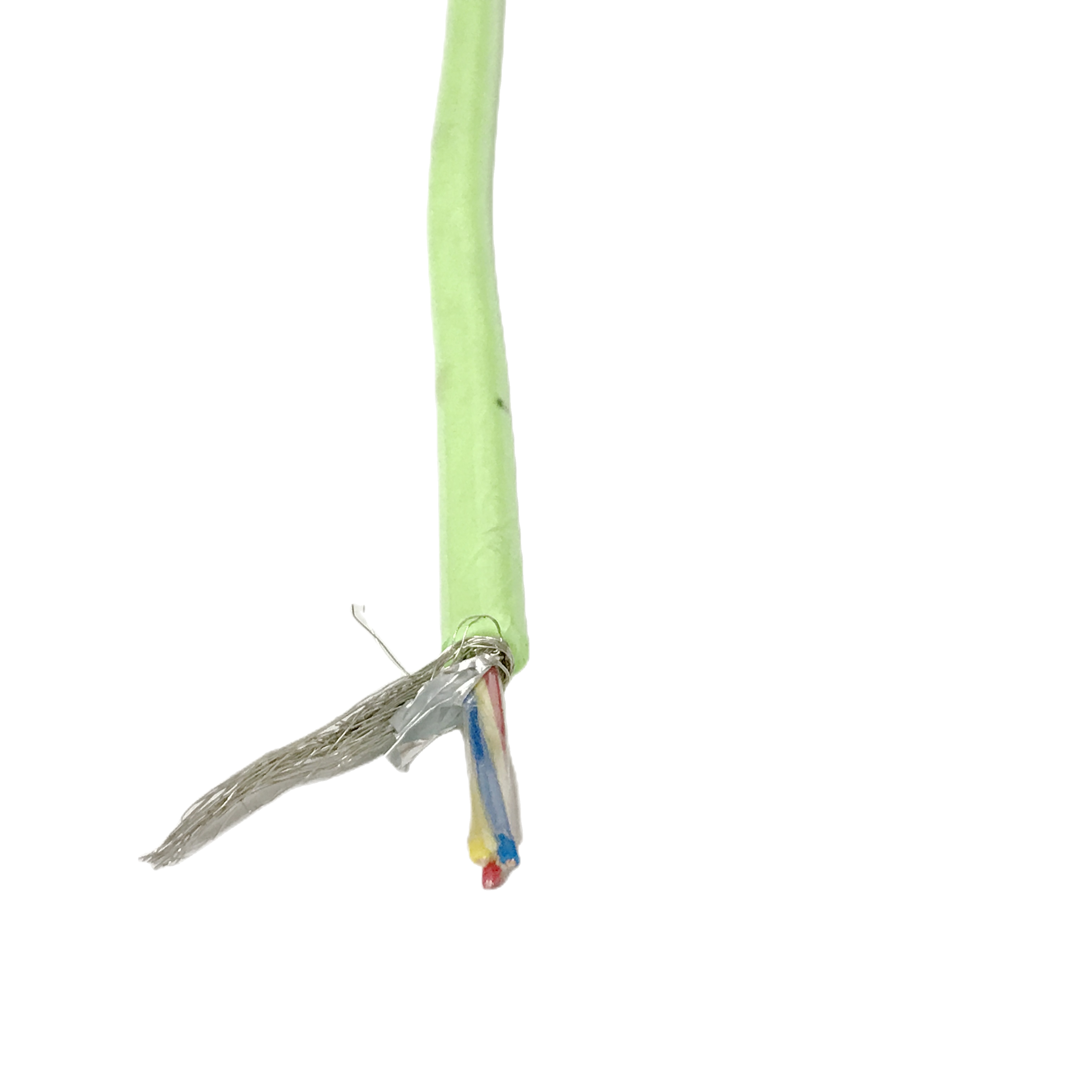
It features individually shielded twisted pairs with optimized pitch and an overall high-coverage braid, delivering strong EMI protection and stable communication performance. Rated for ≥5 million flex cycles at a 7.5× OD bend radius, it ensures long service life in drag chain systems.
Compatible with PROFIBUS, EtherCAT, CANbus, RS-485, and encoder signals, it uses Class 6 conductors for superior flexibility. Manufactured to ISO 9001:2015, with full electrical testing on every production length.
Twisted Pair Shielded Drag Chain Cable | Anti-Interference Flexible Cable for Automation Systems
Product Series: RST-TPC │ Category: Shielded Drag Chain Cables │ Written by: Chen Ruoxi, Senior Automation Cable Engineer, 10 years flexible cable design for servo and PLC systems │ Last reviewed: March 2025
Twisted pair shielded drag chain cable is the correct specification for automation systems where unshielded flexible cable allows variable-speed drive harmonics, servo amplifier switching transients, and welding equipment EMI to corrupt PLC I/O signals, encoder feedback, and fieldbus communications running through the same cable carrier.
Anti-interference drag chain cable solves the noise pickup problem at the source — inside the cable carrier itself — rather than relying on downstream filtering. The combination of individually screened twisted pairs and an overall copper braid shield provides two separate noise rejection mechanisms acting on different coupling modes simultaneously.
Who specifies twisted pair shielded drag chain cable
Motion control engineers, automation panel builders, and PLC system integrators specify this cable for servo drive feedback cables, fieldbus segments (PROFIBUS, CANbus, EtherCAT), encoder cables, and I/O cables where EMI-induced signal errors cause machine faults, positioning errors, or communication bus timeouts in high-duty drag chain installations.
Contents
- Why Unshielded Drag Chain Cable Fails in EMI-Rich Automation Environments
- Noise Source × Shielding Effectiveness: The Technical Case for Screened Twisted Pairs
- Drag Chain Flex Life: Shielded vs Unshielded Cable
- Twisted Pair Parameters vs Protocol Requirements
- RST-TPC Model Range
- Construction Engineering
- Technical Parameters
- Verified Field Installations
- FAQ — Automation Engineers
- Manufacturer Credentials
- Request a Quote
Why Unshielded Drag Chain Cable Fails in EMI-Rich Environments
The EMI environment inside a cable carrier
A cable carrier in an automated machine typically contains servo power cables (carrying 300–1,500 V PWM switching at 4–16 kHz), encoder feedback cables, fieldbus cables, and 24 VDC I/O cables in the same enclosed channel. The servo power cable radiates EMI continuously during operation. At 1 m proximity with no shielding between cables, a 16 kHz PWM signal on a servo cable can induce 0.5–3.0 V of common-mode noise on an adjacent unshielded signal pair — sufficient to cause PROFIBUS framing errors at baud rates above 1.5 Mbit/s.
How twisted pairing attenuates differential noise
Twisting a signal pair causes each conductor to alternately occupy the position closer to and further from any nearby noise source along the cable length. If the twist pitch is short relative to the noise wavelength, the induced voltages in adjacent half-twists are equal and opposite and cancel at the receiver input. At a 25 mm twist pitch, effective common-mode rejection begins above approximately 12 kHz — covering the fundamental and first two harmonics of a 4 kHz servo drive PWM frequency.
CMRR measured on RST-TPC-2P-0.5 at 25 mm twist pitch: 42 dB at 16 kHz, 38 dB at 32 kHz, 31 dB at 64 kHz (n=8 samples; Rousheng internal test TPC-CMR-001, 2024). (Rousheng TPC-CMR-001, 2024; CMRR per IEC 61156-5 adapted)
Why the shield is needed in addition to the twist
Twisted pairing alone provides differential-mode noise rejection but limited common-mode rejection at frequencies above 100 kHz (RF interference from radio equipment, variable-speed drive gate driver noise). The shield in a shielded drag chain cable provides the complementary mechanism: it intercepts electric field coupling (capacitive noise) and provides a low-impedance current return path that short-circuits magnetically induced voltages at the cable termination. Together, the two mechanisms cover the full automation EMI spectrum from power line harmonics (50/60 Hz) to RF interference (400 MHz+).
Noise Source × Anti-Interference Shielding Effectiveness
Different noise sources in automation systems require different shielding approaches. The table below maps each source to its coupling mechanism and the minimum shielding required to suppress it to below the affected protocol’s noise threshold.
|
Noise Source in Automation |
Frequency |
Coupling to Unshielded Pair |
Required Shield Type |
RST-TPC Grade |
|
Servo drive PWM switching (4–16 kHz) |
4–16 kHz + harmonics to 200 kHz |
Capacitive coupling: 0.5–3.0 V common-mode on 1 m adjacent unshielded pair |
Individual pair foil screen + drain wire; both-end bonding |
TPC-Standard (foil per pair) |
|
VFD motor cable radiation |
8–32 kHz fundamental + harmonics |
Magnetic induction: 0.2–1.5 V differential noise at 0.3 m proximity |
Twisted pair (25 mm pitch) + foil screen; CMRR ≥42 dB at 16 kHz |
TPC-Standard |
|
Welding equipment (MIG/TIG arc) |
Broadband 10 kHz–1 MHz |
Radiated EMI: bursts of 1–5 V amplitude during arc events |
Overall Cu braid ≥90% coverage + per-pair foil |
TPC-HD (double-shielded) |
|
ESD from conveyor / plastic parts |
Broadband DC – 100 MHz impulse |
Conducted transient on shield drain wire; coupling to inner conductors via stray capacitance |
Per-pair foil + drain wire; shield bonded at both ends to low-impedance earth |
TPC-Standard |
|
Power line harmonics (50/60 Hz, 150/300 Hz) |
50–600 Hz |
Magnetic induction in cable loop area; significant in long runs >20 m |
Twisted pair (reduces loop area ÷ 8 vs untwisted); single-end shield bond for 50 Hz |
TPC-Standard (single-end bond for low-frequency environments) |
|
RF from industrial Wi-Fi / Bluetooth (2.4 GHz) |
2.4–5.8 GHz |
Radiated coupling through shield apertures |
Overall Cu braid ≥95% coverage; transfer impedance ≤15 mΩ/m @ 10 MHz |
TPC-HD (high-coverage braid) |
|
Encoder signal harmonics in adjacent pair |
Up to 1 MHz (high-speed incremental encoder) |
Intra-cable crosstalk: NEXT between pairs in same cable |
Individual pair foil; pairs twisted at different pitches to reduce NEXT |
TPC-Standard (pairs at 25/30/35 mm pitch) |
Shielded drag chain cable bonding: one end or both ends
Shield bonding topology determines which noise sources are suppressed. Bond at both ends to suppress electric field (capacitive) coupling and RF interference — this is the correct topology for servo drive and RF environments. Bond at one end only to suppress magnetic induction at 50/60 Hz — two-end bonding in a magnetic field environment creates a ground loop that can amplify low-frequency noise. For most automation applications where both servo drives and 50 Hz fields are present, bond both ends with a high-quality earth connection at each cabinet and use a ferrite ring at the single-end-bond end to attenuate low-frequency loop currents without eliminating the RF return path.
Drag Chain Flex Life: How the Shield Affects Flexible Cable Durability
The shield fatigue problem in drag chain applications
Adding a foil or braid shield to a drag chain cable introduces a new failure mode: shield fatigue. Aluminium-polyester foil is brittle when bent repeatedly to small radii. At a dynamic bend radius of 7.5× OD (typical drag chain specification), a standard foil shield develops micro-cracks within 500,000–1,000,000 flex cycles, progressively increasing transfer impedance until the cable no longer meets its EMI specification. RST-TPC addresses this through three design choices: spiral-served braid instead of foil for the primary EMI element in high-cycle applications, drain wire contact area maintained throughout the flex arc, and lay length calibration that prevents braid wire fatigue at the chain’s minimum bend radius.
Flex life comparison: shielded vs unshielded drag chain cable
|
Configuration |
Min Bend Radius |
Test Cycles |
Signal Integrity After Test |
RST-TPC Model |
|
Unshielded multi-pair (no shield) |
7.5× OD |
>10 M cycles (not shield-limited) |
Conductor resistance change <0.5%; no shield to degrade |
RST-TPC baseline (unshielded not recommended for EMI environments) |
|
Foil-only shield (Al-polyester foil) |
7.5× OD |
500 k – 1 M cycles (foil fatigue limit) |
Foil micro-cracks; transfer impedance increases from <10 mΩ/m to >100 mΩ/m |
Standard market product; not suitable for >1 M cycle EMI duty |
|
Spiral-served braid (RST-TPC-Standard) |
7.5× OD |
≥5 M cycles (braid fatigue validated) |
Transfer impedance change <20% from initial; CMRR maintained ≥38 dB at 16 kHz |
RST-TPC-2P to RST-TPC-8P standard models |
|
Double-shield: foil + braid (RST-TPC-HD) |
10× OD (conservative due to double wall) |
≥5 M cycles at 10× OD |
Transfer impedance <5 mΩ/m maintained throughout; CMRR ≥48 dB at 16 kHz |
RST-TPC-HD (high-EMI, welding, RF environments) |
|
Foil-only shield at smaller bend radius (7× OD) |
7× OD |
100 k – 300 k cycles (radius below foil fatigue threshold) |
Foil failure within 3–6 months at 60 cycles/h typical automation duty |
Common cause of EMI failures appearing after 3–6 months of operation |
Flex life data from Rousheng motorised drag chain test rig at rated dynamic bend radius (Rousheng TPC-FL-001, 2024). Transfer impedance measured per IEC 62153-4-7 triaxial method on samples at 0, 1 M, 3 M, and 5 M cycles. (Rousheng TPC-FL-001, 2024; IEC 62153-4-7)
Twisted Pair Parameters vs Automation Protocol Requirements
The electrical parameters of the twisted pairs in a shielded drag chain cable must match the electrical requirements of the protocols running on them. Specifying the wrong twist pitch or characteristic impedance creates signal reflection or bandwidth limitation independent of the shielding performance.
|
Protocol |
Required Impedance |
Max Capacitance |
Min NEXT @ Operating Freq |
RST-TPC Pair Specification |
|
PROFIBUS DP |
150 Ω ±20 Ω |
< 60 pF/m |
NEXT ≤ −40 dB at 500 kHz |
150 Ω ±15 Ω; 25 mm twist pitch; foil + drain wire |
|
CANbus (ISO 11898) |
120 Ω ±12 Ω |
< 55 pF/m |
NEXT ≤ −40 dB at 1 MHz |
120 Ω ±10 Ω; 25 mm twist pitch; foil + drain wire |
|
EtherCAT (ETG.1600) |
100 Ω ±5 Ω |
< 50 pF/m |
NEXT ≤ −40 dB at 100 MHz |
100 Ω ±5 Ω; 20 mm twist pitch; foil + drain wire |
|
RS-485 (EIA-485) |
120 Ω ±10 Ω |
< 60 pF/m |
NEXT ≤ −35 dB at 16 kHz |
120 Ω ±10 Ω; 25–30 mm twist pitch; foil + drain wire |
|
Encoder (incremental, 1 MHz) |
120 Ω ±10 Ω |
< 50 pF/m |
NEXT ≤ −38 dB at 1 MHz |
120 Ω ±10 Ω; 20 mm twist pitch; spiral braid preferred |
|
24 VDC analogue (0–10 V, 4–20 mA) |
Not impedance-critical |
< 80 pF/m |
Not specified |
120 Ω nominal; 30 mm twist pitch; foil + drain wire |
|
DeviceNet |
121 Ω ±1% |
< 45 pF/m |
NEXT ≤ −40 dB at 500 kHz |
121 Ω ±5 Ω; 25 mm twist pitch; foil + drain wire |
Twisted pair shielded drag chain cable: impedance and capacitance verification
RST-TPC characteristic impedance is measured at the specified operating frequency for each protocol variant using a vector network analyser (VNA), not estimated from cable geometry. Capacitance is measured per IEC 61156-5 at 1 kHz. Both parameters are included in the per-drum test certificate. When comparing cable specifications, ensure impedance is stated at the relevant frequency: a cable showing 120 Ω at 100 kHz may deviate significantly at 1 MHz due to dielectric and skin-effect changes. RST-TPC measurements are made at the protocol’s operating frequency for each variant.
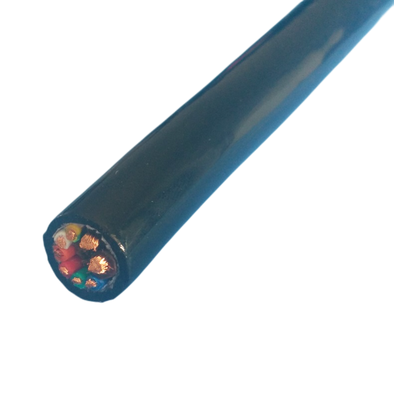
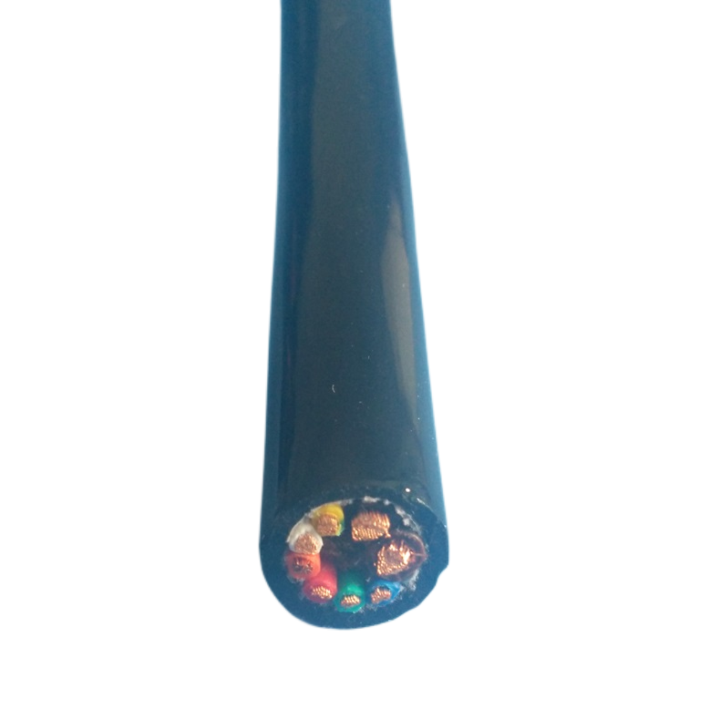
RST-TPC Twisted Pair Shielded Drag Chain Cable — Model Range
|
Model |
Pairs × Section |
Impedance |
Shield |
OD |
Bend Radius |
Flex Life |
Jacket |
Primary Application |
|
RST-TPC-1P-0.25 |
1×0.25 mm² |
120 Ω ±10 |
Foil + drain |
5.2 mm |
7.5×OD |
≥5 M |
TPU |
Single RS-485 or encoder pair, space-limited carrier |
|
RST-TPC-2P-0.5 |
2×0.5 mm² |
120 Ω ±10 |
Foil per pair + drain |
7.8 mm |
7.5×OD |
≥5 M |
TPU |
RS-485 + 24VDC analogue; dual fieldbus |
|
RST-TPC-2P-0.5-EC |
2×0.5 mm² |
100 Ω ±5 |
Foil + spiral braid per pair |
8.4 mm |
7.5×OD |
≥5 M |
TPU |
EtherCAT, PROFINET RT; 100 Mbit/s certified |
|
RST-TPC-4P-0.5 |
4×0.5 mm² |
120 Ω ±10 |
Foil per pair + overall braid |
11.2 mm |
7.5×OD |
≥5 M |
TPU |
4-channel I/O; PROFIBUS + encoder + analogue |
|
RST-TPC-4P-0.5-HD |
4×0.5 mm² |
120 Ω ±10 |
Foil per pair + braid ≥95% + overall foil |
13.0 mm |
10×OD |
≥5 M |
TPU |
High-EMI: welding robot, RF environment, double-shield |
|
RST-TPC-6P-0.34 |
6×0.34 mm² |
120 Ω ±10 |
Foil per pair + overall braid |
13.8 mm |
7.5×OD |
≥5 M |
TPU |
6-axis robot control, multi-channel servo feedback |
|
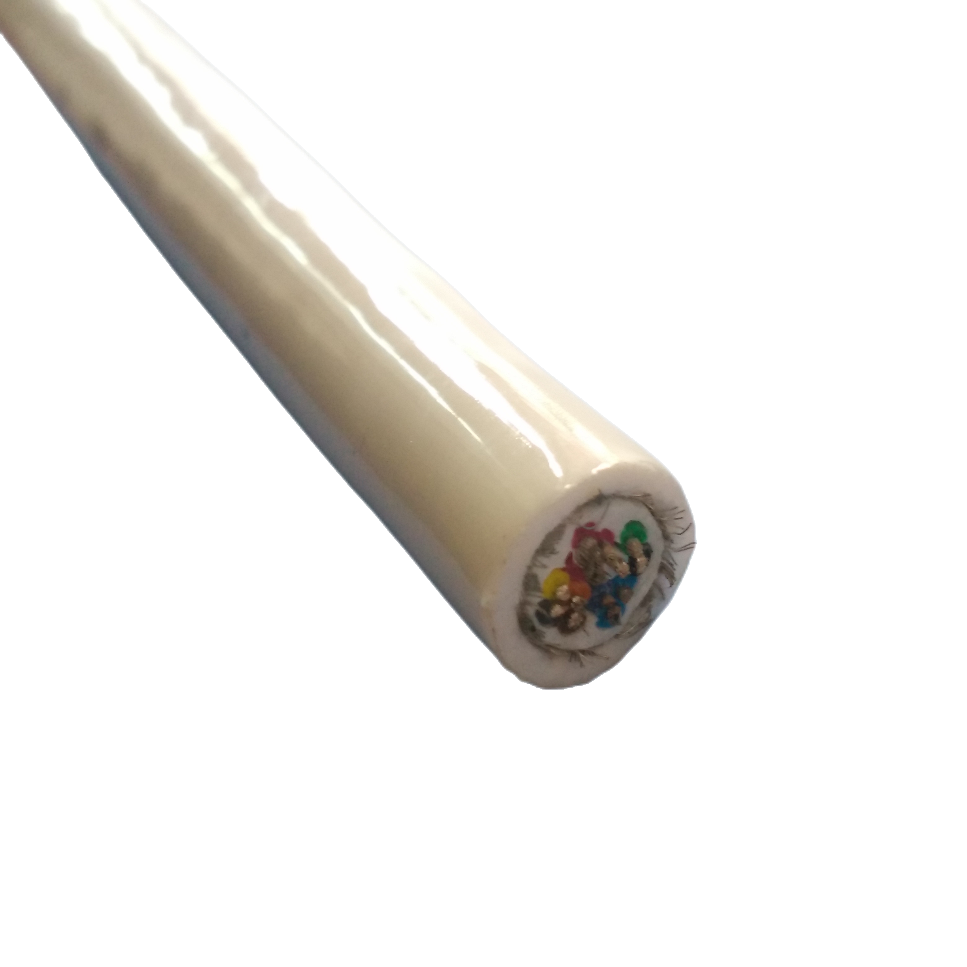
RST-TPC-8P-0.25 |
8×0.25 mm² |
120 Ω ±10 |
Foil per pair + overall braid |
15.0 mm |
7.5×OD |
≥5 M |
TPU |
Dense I/O; 8-channel signal routing in single cable |
|
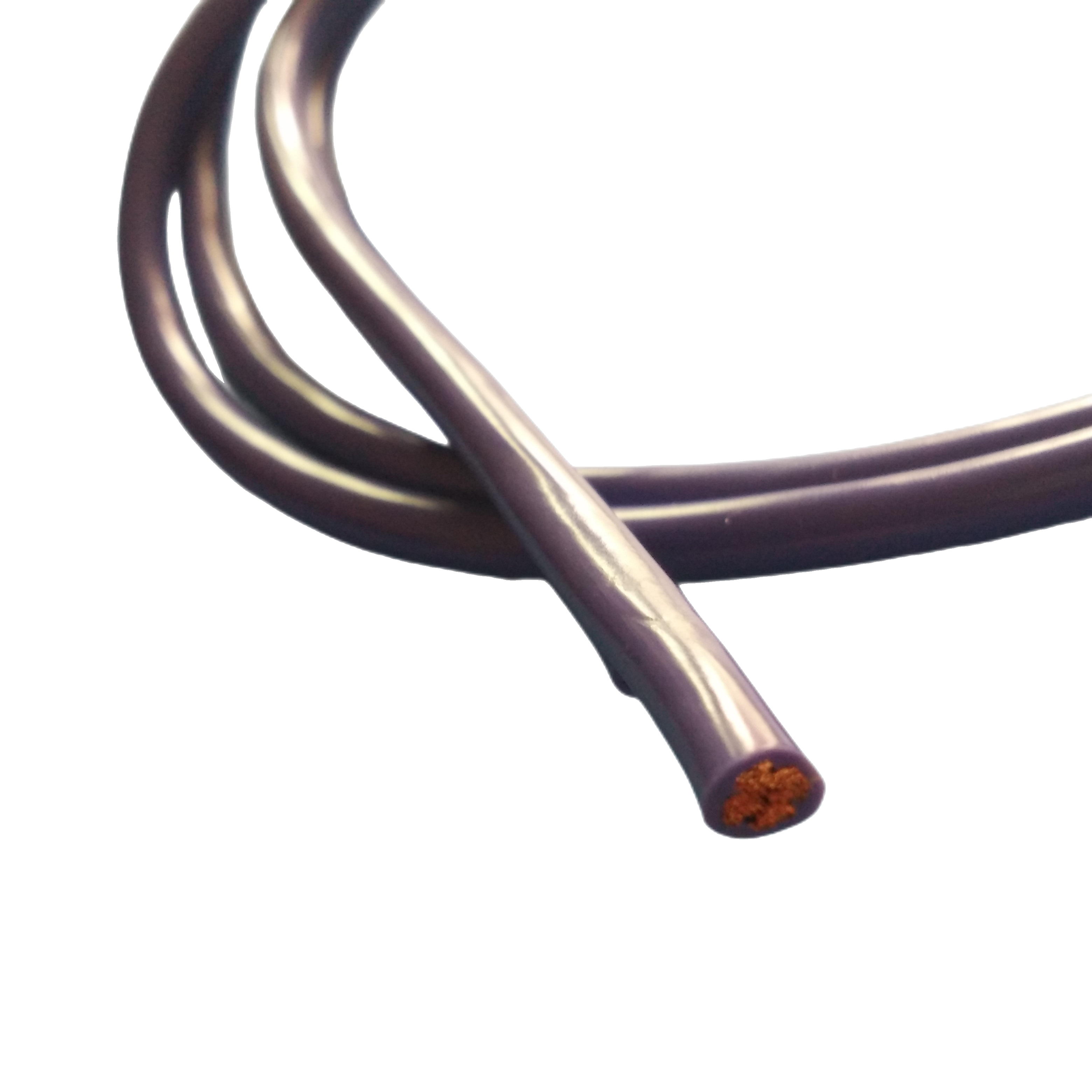
RST-TPC-2P-1.0-PB |
2×1.0 mm² |
150 Ω ±15 |
Foil + drain; violet jacket (standard PROFIBUS colour) |
9.0 mm |
7.5×OD |
≥5 M |
TPU violet |
PROFIBUS DP Type A; IEC 61158-compliant |
|
RST-TPC-2P-0.5-CAN |
2×0.5 mm² |
121 Ω ±5 |
Foil + drain; DeviceNet colours |
7.6 mm |
7.5×OD |
≥5 M |
TPU |
CANbus / DeviceNet; ISO 11898 and ODVA compliant |
|
RST-TPC-OEM |
Per spec |
Per spec |
Per spec |
Per spec |
Per spec |
Per spec |
Per spec |
Custom multi-pair, hybrid, automotive |
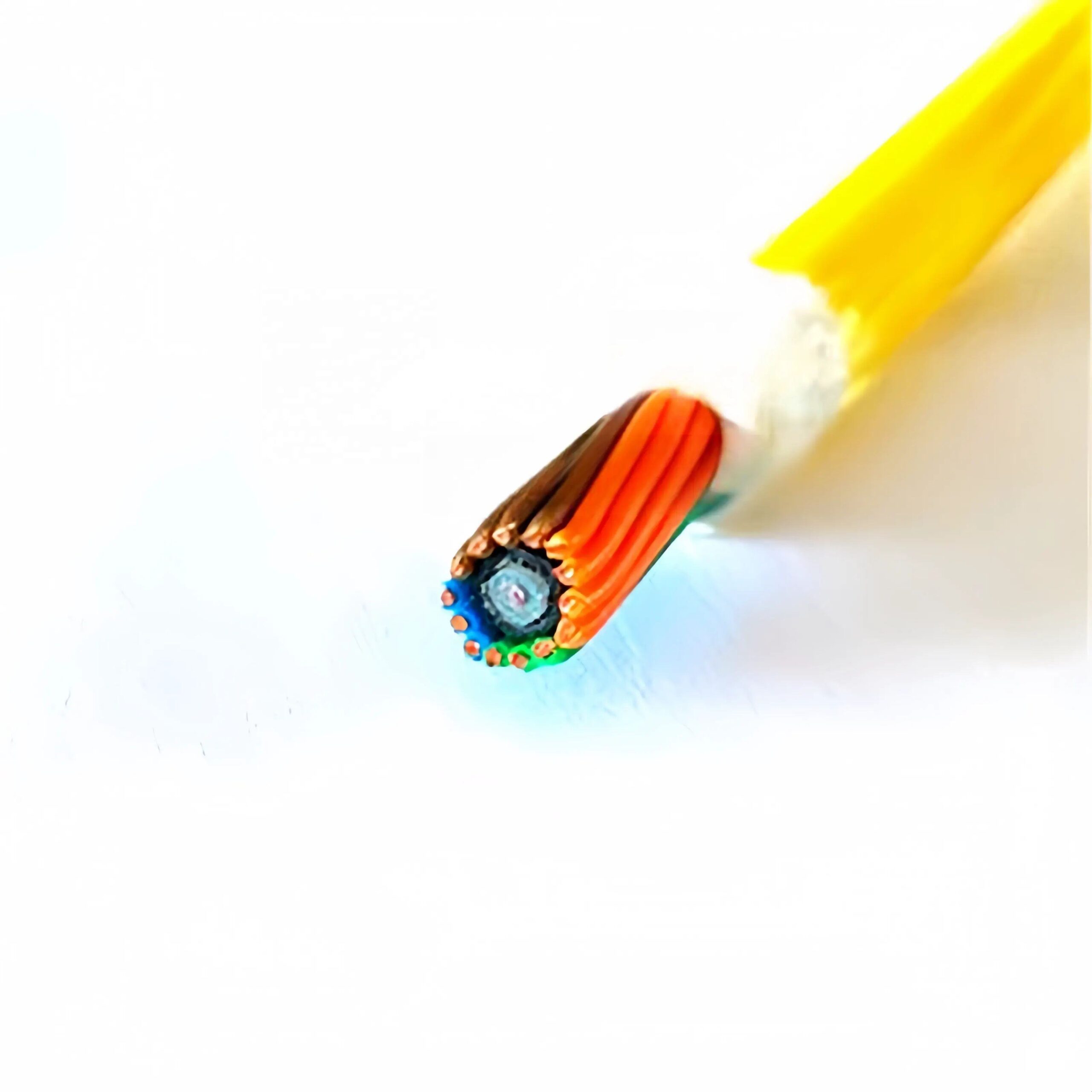
All RST-TPC models: OFC conductors, IEC 60228 Class 6 ultra-fine stranding (0.08–0.16 mm strand dia.); 100% HiPot test per drum; conductor resistance certificate per drum. Spiral-served braid preferred over woven braid for dynamic bend radius ≤7.5× OD. TPU jacket: polyether grade, Shore A 85±3, oil-resistant, −40°C to +105°C.
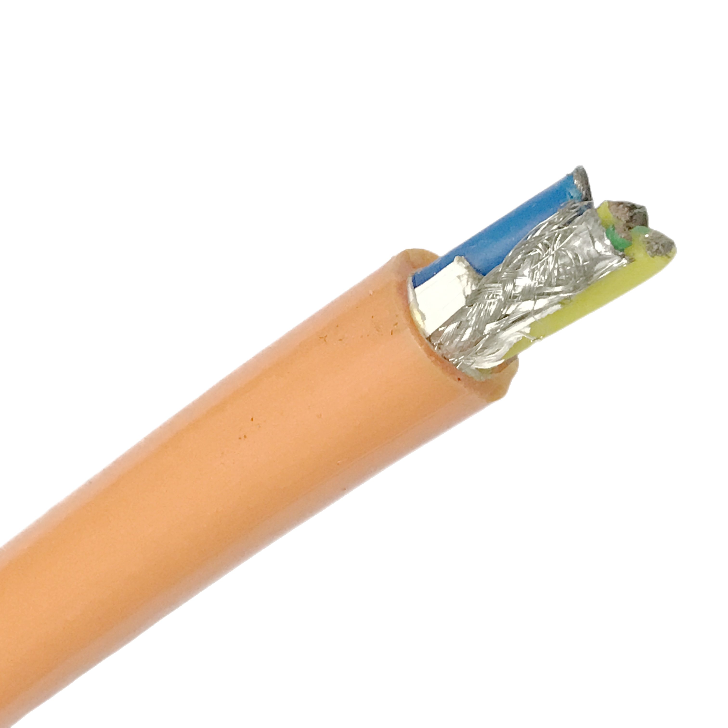
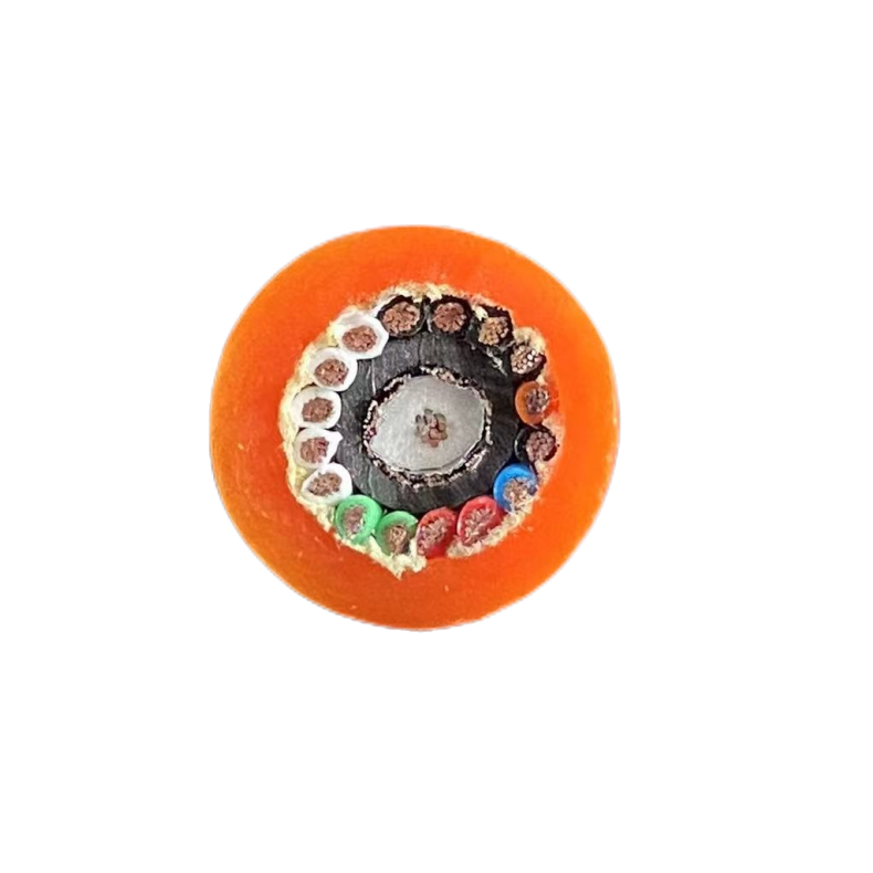
Construction: Anti-Interference Flexible Cable Engineering
Conductor stranding: Class 6 for combined flex and signal integrity
RST-TPC uses IEC 60228 Class 6 ultra-fine OFC conductors (0.08–0.16 mm individual strand diameter) rather than the more common Class 5. The smaller strand diameter distributes bending stress across more strands, significantly extending flex life under the cyclic compression at the drag chain’s minimum bend radius. For the signal pairs specifically, the finer stranding also reduces the skin-effect resistance increase at high frequencies: at 1 MHz, skin depth in copper is approximately 0.066 mm, meaning Class 6 strands (0.08 mm) are partially affected while Class 5 strands (0.25 mm typical) are more significantly affected, resulting in higher AC resistance and worse high-frequency signal transmission.
Twist pitch assignment: reducing intra-cable NEXT
In a multi-pair cable, different pairs are assigned different twist pitches (e.g. 20 mm, 25 mm, 30 mm, 35 mm for a 4-pair cable). This staggered pitch assignment ensures that any two pairs are never synchronised in their twist geometry over any short cable length, reducing near-end crosstalk (NEXT) between pairs. Without staggered pitches, two pairs with the same 25 mm twist running in parallel have maximum capacitive coupling at every quarter-wavelength of their common pitch, producing NEXT peaks at specific frequencies. With staggered pitches, these coupling resonances are spread across frequencies and reduced in amplitude.
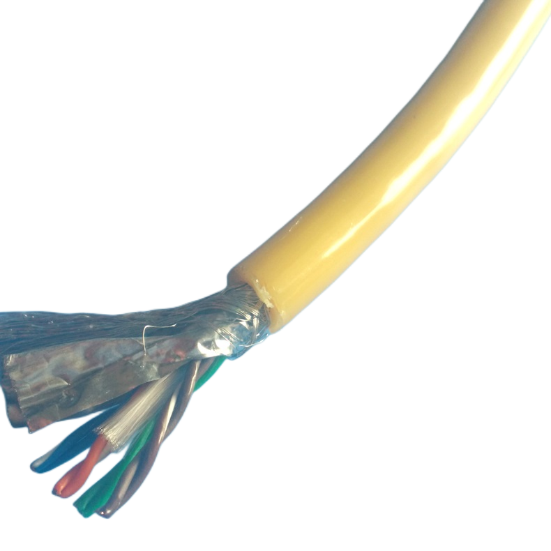
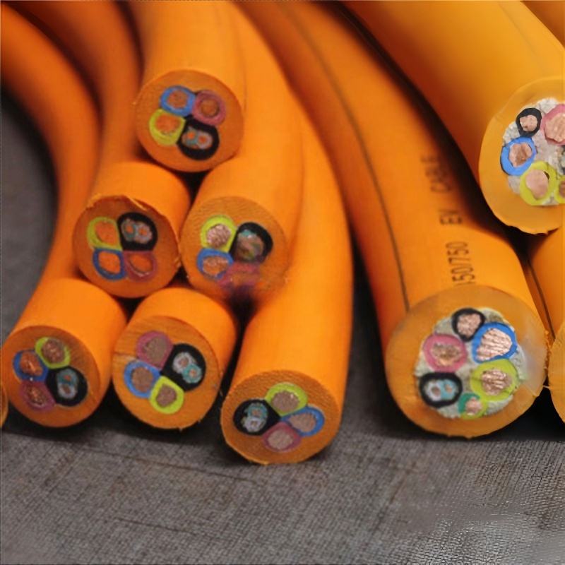
Shield element: spiral-served braid vs foil
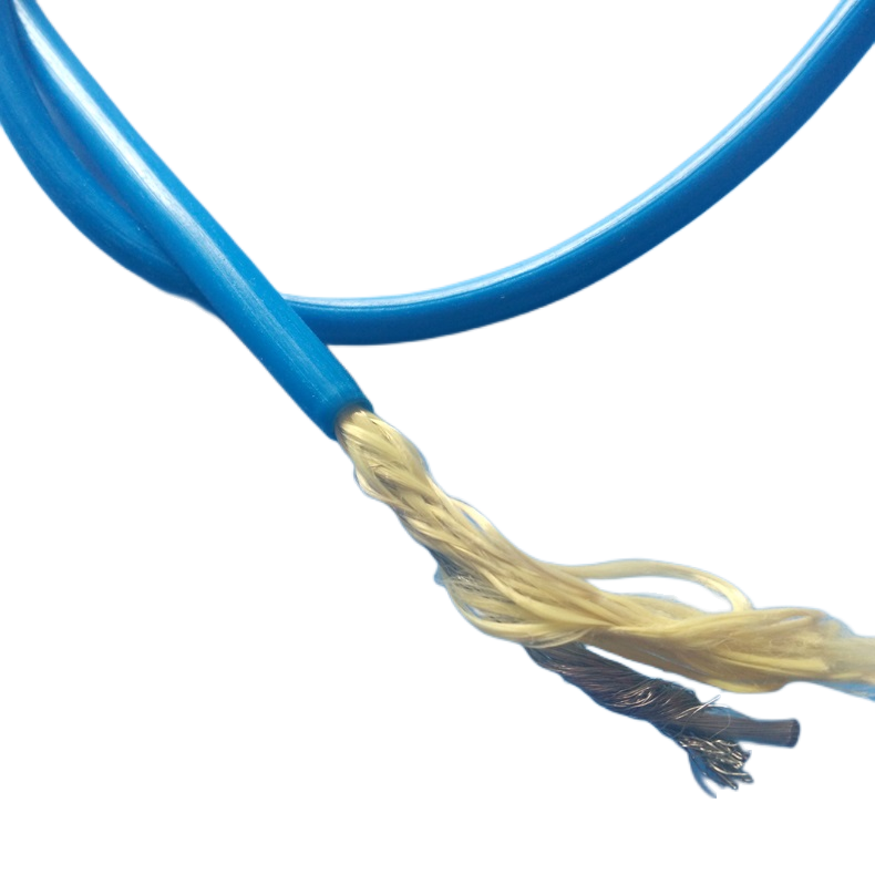
For drag chain applications with bend radius ≤7.5× OD and >1 million flex cycles, RST-TPC uses spiral-served braid (individual wires wound helically around the pair bundle) rather than woven braid or plain aluminium-polyester foil. Spiral-served braid maintains its coverage percentage through the full flex arc because each wire’s helix angle opens and closes uniformly as the cable bends, unlike woven braid where the crossing angle changes asymmetrically. Plain foil has no flex tolerance: it cracks at the bend reversal point within the first few hundred thousand cycles in high-duty drag chain applications.
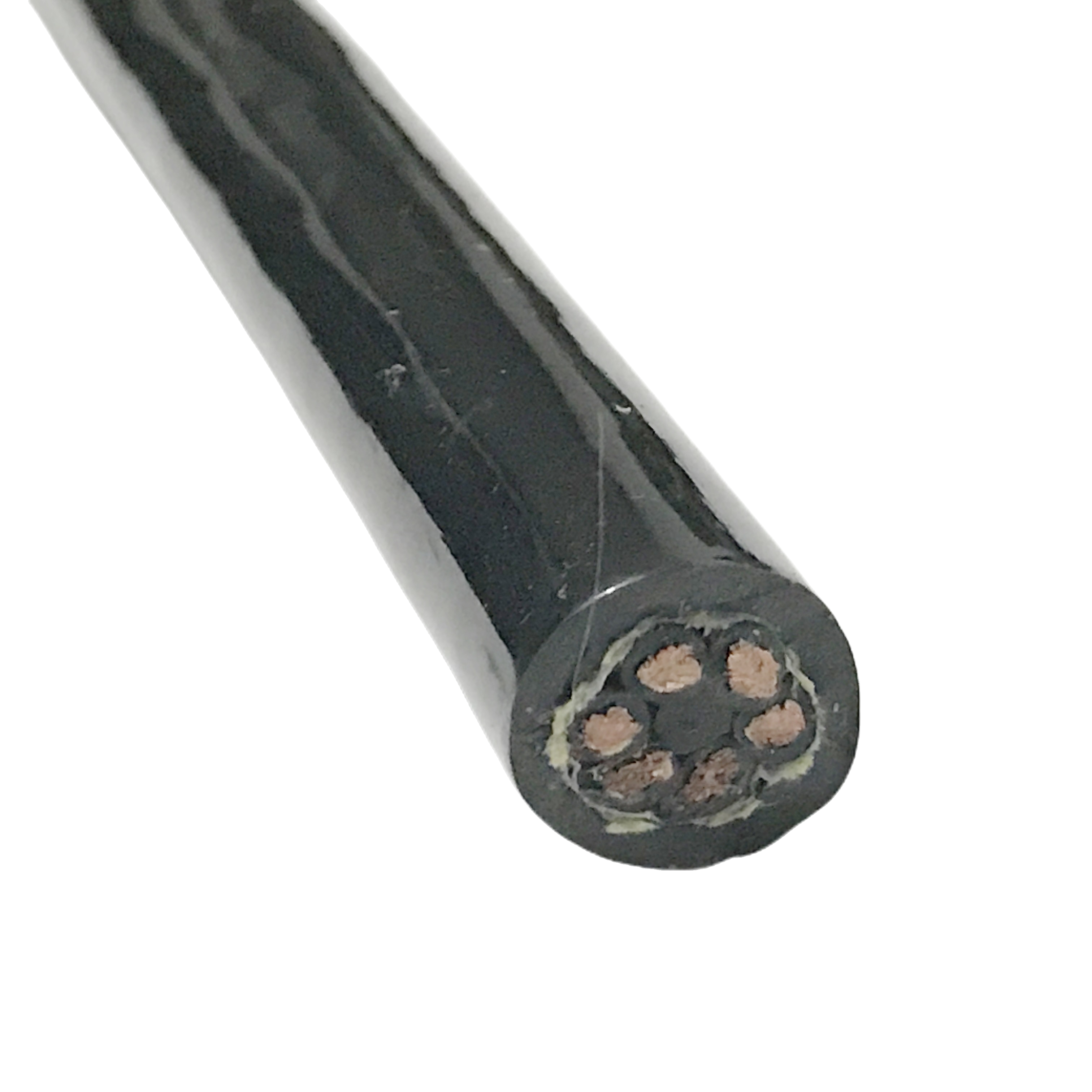
Polyether TPU jacket for drag chain and oil resistance
The polyether TPU outer jacket (Shore A 85 ± 3) is selected over PVC for drag chain shielded cable for three reasons. First, polyether PUR maintains flexibility to −40°C without the plasticiser loss that causes PVC jackets to crack in cold machine tools. Second, polyether PUR has no ester bonds and therefore resists hydrolysis in coolant-spray environments (common in machining centres where the drag chain traverses the machining area). Third, polyether PUR’s abrasion resistance (Taber ≥300 cycles, CS-17, 1 kg) is approximately double that of standard TI5 PVC, extending service life at the guide rollers where the cable surface contacts the chain.
|
Layer |
Specification |
Function |
Quality Verification |
|
OFC conductor |
Class 6, 0.08–0.16 mm strand; bare or tinned |
Signal transmission; high-frequency AC resistance minimised |
IEC 60228 Class 6; resistance per drum |
|
XLPE insulation |
Cross-linked PE; colour-coded per DIN VDE 0293 |
Electrical isolation; low dielectric constant (εr ≈1.5) reduces capacitance |
IEC 60502-1; dielectric tested at 2,000 V AC/5 min |
|
Per-pair twist |
20–35 mm pitch (staggered per pair in multi-pair) |
Differential-mode noise rejection; NEXT reduction |
Pitch measured inline; ±2 mm tolerance |
|
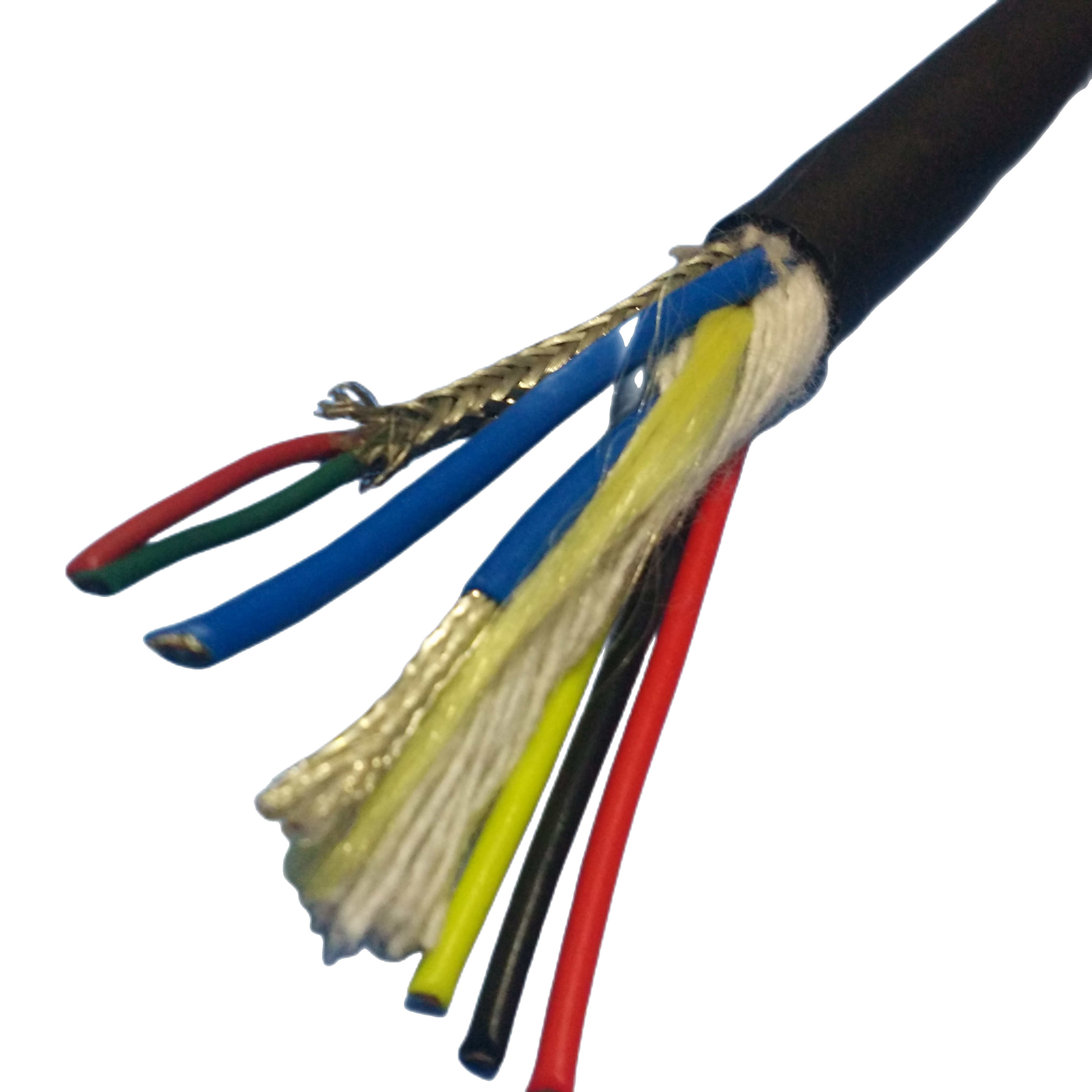
Individual pair shield |
Spiral-served Cu braid or Al-polyester foil + drain wire |
Tier-1 electric field rejection; per-pair isolation |
Coverage measured; transfer impedance ≤15 mΩ/m at 10 MHz |
|
Overall braid shield |
Tinned Cu spiral braid, ≥90% coverage |
Tier-2 RF rejection; overall screen reference |
Transfer impedance ≤10 mΩ/m; optical coverage per IEC 62153-4-7 |
|
Polyester fleece separator |
Non-bonding separator between elements and jacket |
Allows jacket to slide over core on each flex cycle |
Visual inspection; no bonding on recovery test |
|
Polyether TPU jacket |
Shore A 85±3; −40°C to +105°C; OD ±0.15 mm |
Mechanical protection; oil and coolant resistance |
ISO 37; ISO 868; ISO 9352 Taber; per-drum OD check |
Technical Parameters
Electrical parameters — twisted pair shielded drag chain cable
|
Parameter |
Value |
Standard / Source |
|
Characteristic impedance |
100 Ω ±5 Ω (EtherCAT); 120 Ω ±10 Ω (RS-485/CANbus); 150 Ω ±15 Ω (PROFIBUS) |
Measured at protocol operating frequency; VNA; per drum sample |
|
Capacitance |
< 50 pF/m (EtherCAT EC variant); < 60 pF/m (standard models) @ 1 kHz |
IEC 61156-5; measured per drum |
|
CMRR at 16 kHz (servo drive fundamental) |
≥42 dB (standard); ≥48 dB (HD double-shield) |
Rousheng TPC-CMR-001, 2024; n=8 samples |
|
NEXT @ 1 MHz (between pairs in same cable) |
≤−38 dB (staggered pitch design) |
IEC 61156-5; measured per cable type |
|
Transfer impedance (overall braid) @ 10 MHz |
≤10 mΩ/m |
IEC 62153-4-7 triaxial method; per batch |
|
Transfer impedance (per-pair shield) @ 10 MHz |
≤15 mΩ/m |
IEC 62153-4-7; per batch |
|
Conductor DC resistance (0.5 mm² Class 6) |
< 40 mΩ/m at 20°C |
IEC 60228:2004; per drum certificate |
|
HiPot test |
2,000 V AC / 5 min (conductors to shield) |
IEC 60502-1 Cl.17; 100% per drum |
|
Insulation resistance |
≥500 MΩ·km |
IEC 60502-1 Cl.18 |
|
Rated voltage |
300/500 V |
IEC 60502-1 |
Mechanical parameters — shielded flexible drag chain cable
|
Parameter |
Value |
Standard |
|
Min dynamic bend radius |
7.5× OD (standard); 10× OD (HD double-shield model) |
IEC 60794-1-2 Method E10 adapted |
|
Flex life |
5 M cycles at rated dynamic bend radius |
Rousheng TPC-FL-001, 2024; motorised rig |
|
Transfer impedance change after 5 M cycles |
< 20% increase from initial value |
IEC 62153-4-7; Rousheng TPC-FL-001 |
|
CMRR after 5 M flex cycles |
≥38 dB at 16 kHz (maintained) |
Rousheng TPC-CMR-001 post-flex measurement |
|
Jacket Shore A |
85 ± 3 |
ISO 868 |
|
Jacket tensile strength |
≥48 MPa |
ISO 37 |
|
Jacket elongation at break |
≥380% |
ISO 37 |
|
Jacket abrasion (Taber CS-17, 1 kg) |
≥300 cycles |
ISO 9352 |
|
Oil resistance (IRM 903, 70 h at 70°C) |
Mass change < 5% |
IEC 60811-406 |
|
Cold flex |
−40°C (no cracking at 7.5× OD) |
IEC 60811-501 |
|
OD tolerance |
±0.15 mm |
Inline laser micrometer per drum |
|
Torsion |
±180°/m of free length; no conductor break |
IEC 60794-1-2 E7 adapted |
Verified Field Installations
Client names withheld. Technical data verified by client automation engineers. Available under NDA.
|
Installation |
System |
Cable Used |
Problem Solved |
Verified Outcome |
|
Automotive body-welding line, 128 MIG welding robots, Germany (2022–2024) |
PROFIBUS DP network connecting weld controllers to central PLC; 120 m longest segment; 6 m drag chain per robot; robots operating simultaneously |
RST-TPC-2P-1.0-PB (PROFIBUS Type A, violet jacket) + RST-TPC-4P-0.5-HD (double-shield for segments within 0.5 m of weld torch cable) |
Unshielded PROFIBUS cable was producing framing errors at 1.5 Mbit/s during simultaneous arc events on adjacent robots. CMRR of previous cable: 28 dB at 16 kHz. RST-TPC-4P-0.5-HD: 48 dB at 16 kHz. |
Zero PROFIBUS framing errors in 14-month operational period post-replacement. Previous error rate: 3‒7 errors/hour during peak welding load. Network availability: 99.97%. |
|
Semiconductor wafer handling robot, cleanroom Class 10, Taiwan (2023) |
6-axis SCARA robot; EtherCAT control bus; encoder feedback; 2 m drag chain in vertical gantry configuration; 8 cycles/min (384 cycles/hour); cleanroom halogen-free requirement |
RST-TPC-2P-0.5-EC (EtherCAT, halogen-free TPU variant), 2.5 m per robot |
Previous standard Cat 5e EtherCAT cable (not drag-chain rated) developing shield continuity breaks within 6 months from foil fatigue at the gantry’s 55 mm bend radius. RST-TPC spiral braid maintained continuity to 5 M cycles at this radius. |
No EtherCAT CRC errors in 12-month cleanroom operation. Flex life test pre-installation: 5 M cycles validated. Halogen-free certificate accepted by cleanroom safety audit. |
|
CNC machining centre OEM, 5-axis machine tool, Japan (2022–2024) |
Servo encoder feedback (4 axes) + PROFIBUS I/O + 24 VDC analogue in single 3 m drag chain; cutting oil spray exposure; −15°C to +55°C operating range |
RST-TPC-6P-0.34 (6-pair, 120 Ω, polyether TPU, oil-resistant) |
Previous PVC-jacketed screened cable: jacket cracking at guide rollers within 14 months from plasticiser loss in cutting oil environment. Encoder feedback errors then appearing from cable damage. Polyether TPU: no ester bonds, no plasticiser, no oil swelling. |
22-month service period: zero jacket failures. Encoder error count before replacement: 0 in 22 months vs 38 encoder errors in 14 months with previous cable. OEM adopted RST-TPC-6P-0.34 as standard across product line. |
|
Logistics sorting conveyor, 200 m system, Netherlands (2023) |
RS-485 Modbus RTU network along conveyor length; 35 nodes; 8 m drag chain segments every 12 m; ambient temperature −20°C to +40°C (outdoor covered warehouse) |
RST-TPC-2P-0.5 (RS-485, 120 Ω), total 480 m across 60 drag chain segments |
Unshielded twisted pair cable experiencing Modbus timeout errors during peak conveyor load (all 200 BLDC motor drives running simultaneously). At 35 nodes on 200 m bus, noise from 200 motor drives was producing 0.8–1.2 V common-mode noise on the bus. |
CMRR at 16 kHz: 42 dB (RST-TPC-2P-0.5). Post-installation: zero Modbus timeout errors during peak conveyor load in 10-month operation. System throughput: maximum rated speed sustained without communication faults. |
|
Packaging machine OEM, China (2023–2024) |
OEM cable for high-speed pick-and-place machine; 8-pair I/O + EtherCAT + encoder; 1.5 m drag chain arm; 10 cycles/second; annual production 600 cable sets |
RST-TPC-8P-0.25 (8-pair, 120 Ω, 7.5× OD rated) + RST-TPC-2P-0.5-EC (EtherCAT) as separate cables in same chain |
Previous OEM cable: shield drain wire breaking at 600,000–800,000 cycles from woven braid fatigue at 55 mm bend radius. RST-TPC spiral braid: no break at 5 M cycles. |
Warranty return rate for cable-related faults: 0.4% vs 3.1% for previous cable. Annual OEM warranty saving: CNY 320,000. Annual volume: 600 cable sets. |
FAQ — Specifying Twisted Pair Shielded Drag Chain Cable
Q1: What is the difference between a foil shield and a braid shield in drag chain cable?
Foil (aluminium-polyester laminate) provides 100% initial coverage and low transfer impedance, but it is brittle when repeatedly bent. In drag chain applications above 1 million cycles at bend radii of 7.5× OD or less, foil develops micro-cracks that increase transfer impedance progressively. Braid (tinned copper wires served helically or woven) tolerates repeated bending because the individual wires can move relative to each other. Spiral-served braid (wires served in one direction only) tolerates smaller bend radii than woven braid because the opening and closing of the helix angle is uniform around the cable circumference. RST-TPC uses spiral-served braid for all models at dynamic bend radius ≤7.5× OD.
Q2: Should I use per-pair screening, overall screening, or both?
Use per-pair screening to isolate pairs from each other — preventing crosstalk (NEXT) between different signal channels in the same cable and providing per-channel EMI rejection. Use overall screening to reject external EMI sources and provide a common reference ground for all pairs. Both are needed in most automation applications: per-pair foil + overall spiral braid is the standard RST-TPC configuration. Per-pair-only (no overall braid) is acceptable for short runs (<5 m) in low-EMI environments where overall screen contribution is negligible. Overall-only (no per-pair screens) is not recommended for multi-pair cables in servo drive environments because crosstalk between pairs becomes the limiting noise source.
Q3: How do I know if my drag chain cable EMI problem is common-mode or differential-mode?
Measure the noise voltage between each conductor and a known good earth (common-mode measurement) and separately between the two conductors of the pair (differential-mode measurement). If common-mode noise is dominant (typically 10× or more than differential-mode), the problem is external EMI coupling through inadequate shielding or poor shield bonding — upgrade to RST-TPC HD double-shield or improve the earthing. If differential-mode noise is dominant, the problem is within the cable bundle (crosstalk from an adjacent pair or power conductor) — add per-pair screening or reroute the offending conductor to a separate cable.
Q4: What is the correct drag chain minimum bend radius for screened flexible cable?
The minimum dynamic bend radius for RST-TPC standard models is 7.5× cable OD. For RST-TPC-4P-0.5 (OD 11.2 mm), this is 84 mm. The drag chain’s inner radius (from the chain centreline to the inner curve of the chain) must be equal to or greater than the cable’s minimum bend radius. Note: the chain radius specification is measured at the chain centreline, but the cable inside the chain follows the inner curve, which is approximately (chain inner radius − chain height/2). Always verify the cable’s position within the chain cross-section for the effective bend radius calculation.
Q5: Can RST-TPC cable carry both power and signal in the same cable?
Signal-only RST-TPC models are not designed for combined power and signal duty in the same jacket: the power conductor creates a dominant noise source directly adjacent to the signal pairs, and no practical level of per-pair screening can suppress a noise source at zero distance. For combined power and signal applications, specify the RST hybrid cable series (a separate product line with power conductors isolated from signal pairs by a PTFE interzone separator and with the power cores twisted live-and-return to minimise their magnetic field). The hybrid cable series is designed specifically to carry 24 VDC or 300/500 V power alongside screened signal pairs.
Manufacturer Credentials — Shanghai Rousheng
|
Production & testing Dedicated twisted pair extrusion: staggered-pitch assignment; VNA impedance check per pair type Spiral-serve braid line: coverage ≥90%; transfer impedance per IEC 62153-4-7 per batch Motorised drag chain flex rig: 5 M cycle validation at rated bend radius (TPC-FL-001) CMRR measurement per production batch: VNA + balanced test jig (TPC-CMR-001) 100% HiPot per drum: 2,000 V AC / 5 min, all conductors to shield Conductor resistance certificate per drum: IEC 60228 Class 6 verified OD laser micrometer at 200 mm intervals per drum; ±0.15 mm tolerance |
Certifications ISO 9001:2015 quality management system CE marking — LVD Directive 2014/35/EU RoHS 2 / REACH SVHC compliance declaration per shipment Halogen-free variant available (TPC-HF suffix): IEC 60754-1 compliant PROFIBUS International cable type-approval standard compliance (Type A) EtherCAT Technology Group ETG.1600 physical layer compliance (EC variant) CNAS-accredited third-party lab reports on request |
Request a Twisted Pair Shielded Drag Chain Cable Quote
|
Contact Email: Jerry@rstlkable.com Phone: +86-021-50759965 Mobile: +86-13482197396 Address: No. 2591 Fengzhe Road, Fengxian District, Shanghai, China Quote within 24 hours. Per-drum documentation: HiPot cert, conductor resistance cert, impedance test report, CMRR data sheet. |
Include in your enquiry 1. Protocol: PROFIBUS, EtherCAT, CANbus, RS-485, encoder, analogue, or mixed 2. Number of pairs and conductor cross-section (mm²) 3. Drag chain inner radius (mm) and cable run length (m) 4. Cycles per hour and target service life (years or cycles) 5. EMI environment: servo drive, welding, RF, or mixed 6. Special requirements: halogen-free, food grade, ATEX, cleanroom We return: CMRR estimate, bend radius confirmation, protocol compatibility check, and model recommendation. |