Spiral Ethernet + Power Cable Manufacturer | Flexible Hybrid Cable for Robotics & Automation
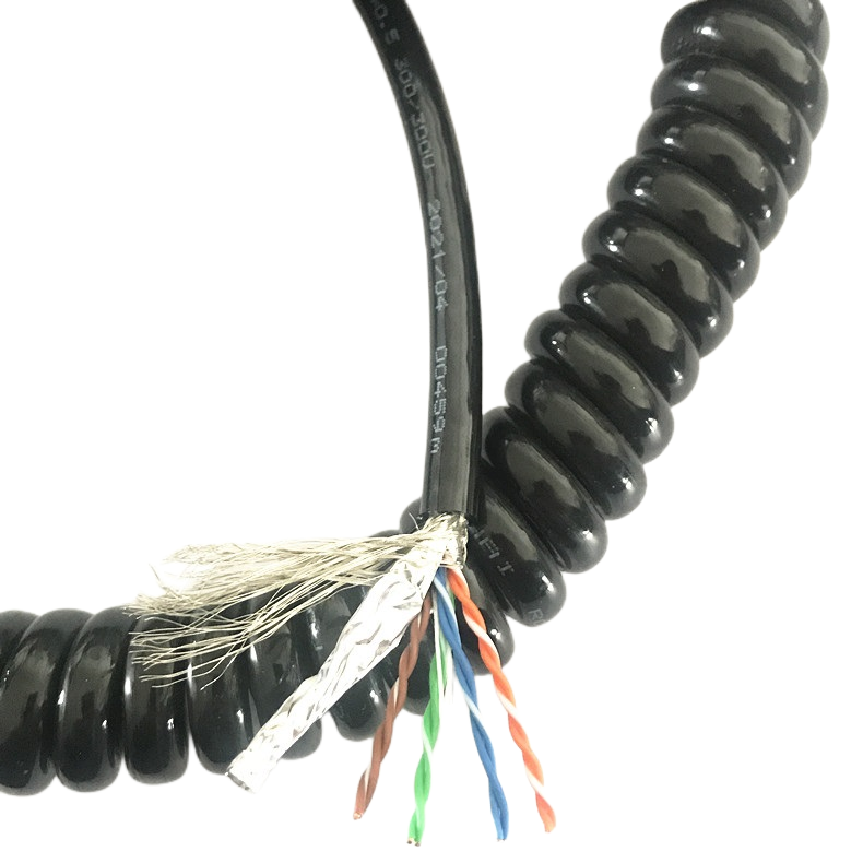
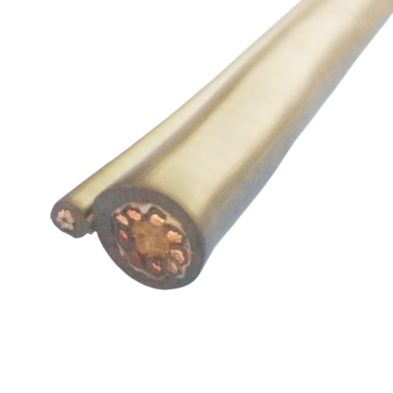
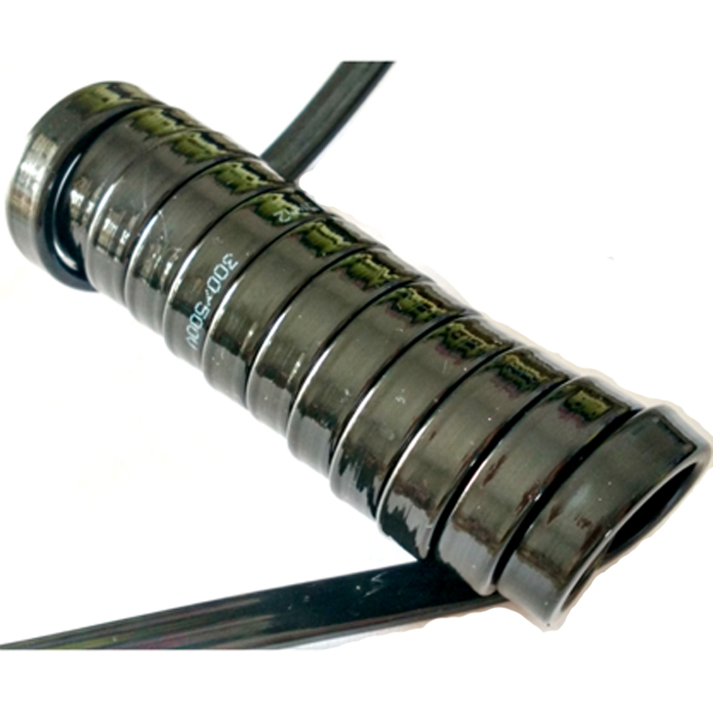
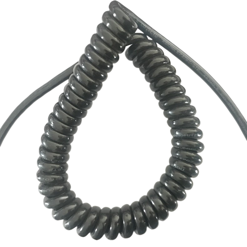
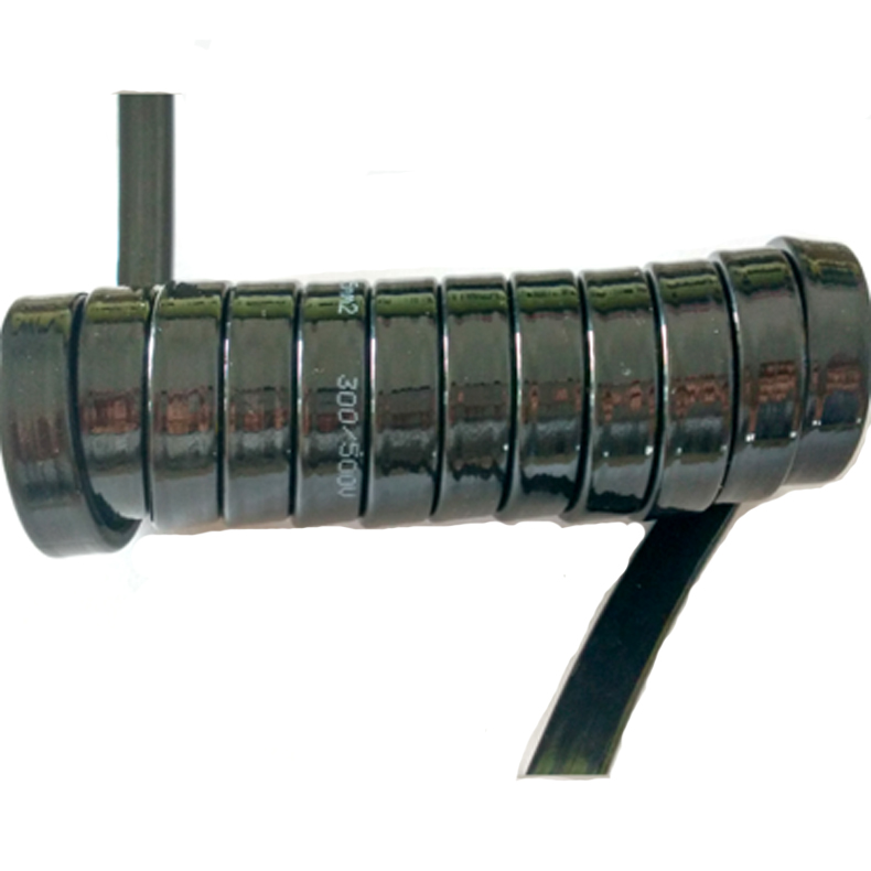
Coiled hybrid cable integrating Cat5e or Cat6 Ethernet pairs with power conductors in a heat-set PUR or TPE spiral jacket. Rated ≥5 million flex cycles. Suitable for robot wrist joints, cobot tool-changer tethers, and AGV docking applications. Custom extension ratios, conductor cross-sections, and connector terminations available.
Coiled Hybrid Cable That Handles 5 Million Flex Cycles: Rousheng’s Spiral Ethernet + Power Solution for Robotics and Automation
Engineers who have wired a 6-axis robotic arm know the frustration: the straight hybrid cable that looked fine during commissioning starts looping, drooping, and eventually chafing against the tooling within three months of production. The root cause is almost never cable quality — it is cable geometry. A straight cable has nowhere to store its own slack when the wrist retracts, so it does the only thing it can: it kinks, it abrades, and it fails.
The spiral Ethernet power cable exists specifically to solve this geometry problem. By manufacturing the outer jacket in a helical coil — heat-set at the factory to a defined rest length and extension ratio — the cable absorbs every millimeter of extension travel and returns cleanly to rest without any external tether management. Rousheng has been producing this cable format since the early drag-chain era, and over that time we have recorded, measured, and learned from thousands of installation failures that informed the current RST-HC series design.
What Separates a Well-Built Spiral Hybrid Cable from One That Fails Early
Most spiral cable failures we investigate at Rousheng trace back to one of three manufacturing shortcuts. Understanding them helps buyers ask the right questions of any supplier.
1. Coil Memory Loss Under Thermal Cycling
A coiled jacket is only as good as its heat-set process. If the PUR compound is extruded at too low a temperature or cooled too quickly, the molecular orientation that creates spring-back memory is incomplete. The cable extends fine in its first thousand cycles — and then the coil relaxes by 30–40% of its original rest length. We see this failure mode consistently in cables produced without a controlled post-extrusion annealing step.
Our production line runs a three-stage thermal conditioning cycle after extrusion: initial set at 75 °C, stress-relief hold at 60 °C, and ambient cool-down over no less than four hours. Skipping any stage saves cycle time but destroys coil memory life. We do not skip it.
2. Impedance Drift in the Data Pairs Under Repeated Extension
Cat5e and Cat6 pairs carry 100 Ω differential impedance. Every time a coiled cable extends and retracts, the pair geometry shifts fractionally. In low-quality designs where the data cores are not individually foil-shielded and bound in a geometry-stable lay, this shift accumulates. After 200,000–400,000 cycles we typically measure impedance drift of ±8–12% on unprotected pairs — enough to cause intermittent EtherCAT packet loss at 100 Mbit/s without triggering a hard fault. The fault is silent and extremely difficult to diagnose in the field.
RST-HC cables use individually foil-shielded pairs with a controlled lay length tolerance of ±2 mm per meter, maintained under dynamic tension during stranding. This keeps impedance drift below ±3% across the full rated flex life.
3. Strain Relief Delamination at the Coil Transition
The mechanical weak point of any spiral cable is not the coil itself — it is the straight lead section where the coil terminates and the cable connects to a connector or junction box. This transition zone experiences both bending and tensile stress simultaneously. Without a bonded strain relief that shares the load across the jacket and the strength member, the junction shears within 50,000–100,000 cycles. We have replaced cables from at least four different suppliers at customer sites where this exact failure mode occurred.
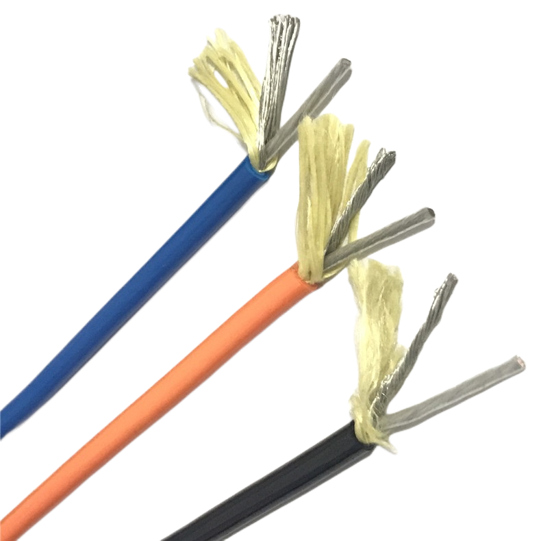
Our strain relief design bonds a Kevlar-reinforced overmold to both the jacket and the connector backshell, distributing tensile load across 35 mm of transition length rather than concentrating it at a single crimp point.
RST-HC Series: Standard Product Matrix
The table below covers Rousheng’s current standard configurations. All parameters reflect production-validated specifications, not theoretical maximums. Custom combinations — including additional power cores, shielded RS-485 pairs alongside Ethernet, or non-standard extension ratios — are handled as engineered-to-order items with typical lead time of 3–5 weeks.
|
Model |
Ethernet |
Power cores |
OD (mm) |
Rest / Extended |
Flex life |
Jacket |
|
RST-HC-100 |
1× Cat5e pair |
2× 0.75 mm² |
7.8 ± 0.3 |
0.3 m / 1.0 m |
≥5M cycles |
PUR |
|
RST-HC-200 |
1× Cat5e pair |
2× 1.5 mm² |
9.2 ± 0.3 |
0.3 m / 1.1 m |
≥5M cycles |
PUR |
|
RST-HC-300 |
1× Cat6 pair |
2× 1.5 mm² |
10.4 ± 0.3 |
0.4 m / 1.6 m |
≥5M cycles |
PUR / TPE |
|
RST-HC-400 |
2× Cat6 pairs |
3× 1.5 mm² |
13.0 ± 0.4 |
0.5 m / 2.0 m |
≥5M cycles |
PUR / TPE |
|
RST-HC-500 |
2× Cat6 + 1× FO |
3× 2.5 mm² |
16.5 ± 0.5 |
0.5 m / 2.5 m |
≥3M cycles |
PUR |
|
RST-HC-C |
Per spec |
Per spec |
8–22 mm |
Custom ratio |
Per design |
PUR / TPE / LSZH |
Note: RST-HC-500 flex life rating is 3M cycles (not 5M) due to the optical fiber element, which has a tighter minimum bend radius requirement than copper pairs. If fiber is not required, the RST-HC-400 at 5M cycles is the recommended alternative for high-duty applications.
Full Technical Specification
|
Electrical parameters |
Mechanical & environmental parameters |
|
Rated voltage (power cores) 300/500 V AC, UL/IEC rated Insulation resistance ≥100 MΩ · km at 20 °C Data pair impedance 100 Ω ± 8% (Cat5e) | 100 Ω ± 5% (Cat6) NEXT (near-end crosstalk) ≥35 dB @ 100 MHz (Cat5e) | ≥44 dB @ 250 MHz (Cat6) EMI shielding (overall braid) Tinned copper braid ≥ 85% coverage; transfer impedance < 30 mΩ/m @ 1 MHz |
Dynamic flex life ≥5,000,000 cycles (Cu pairs); ≥3,000,000 cycles (FO models) Min. dynamic bend radius 6 × OD in coiled section; 4 × OD in straight lead Operating temperature −40 °C to +90 °C (PUR) | −30 °C to +105 °C (TPE) | −15 °C to +70 °C (LSZH) Oil & fluid resistance IEC 60811-2-1; PUR withstands ISO 6945 Group 2 cutting fluids, hydraulic oil Flame retardancy IEC 60332-1 standard; IEC 60332-3 / LSZH option for clean-room or enclosed enclosures |
Spiral Cable vs. Drag Chain Cable: Choosing the Right Format for Your Application
This is the question Rousheng’s application engineers answer most frequently. The short answer: spiral cables are not a universal replacement for drag chains, and drag chains are not always the better choice. The decision depends on four variables — stroke length, cycle speed, installation space, and maintenance access.
|
Evaluation criterion |
Spiral / coiled hybrid cable |
Drag chain cable |
|
Maximum stroke |
Up to 2.5 m (standard); 4 m engineered-to-order |
Virtually unlimited; drag chains scale to tens of meters |
|
Cycle speed |
High-speed cycles (cobot wrist: 200–400 cycles/min) — spring return is passive, no mechanical drag |
Speed limited by chain articulation; vibration at very high cycle rates |
|
Installation footprint |
Minimal — no guiding trough or protective channel required; ideal for confined workcells |
Requires full stroke clearance plus chain trough; significant floor or overhead space |
|
Cable protection |
Relies on jacket toughness; PUR provides good abrasion and cut resistance |
Chain links provide mechanical protection from external impact and weld spatter |
|
Maintenance |
No scheduled maintenance; inspect visually at PM intervals |
Chain links require periodic inspection, lubrication on some designs, and eventual link replacement |
|
Best fit |
Cobot / collaborative robot wrist, AGV docking tether, tool-changer cable, short-stroke reciprocating axis |
Gantry, linear axis > 3 m stroke, welding positioner, any application requiring weld-spatter protection |
|
FIELD NOTE |
In a 2023 automotive body-shop project, a Tier-1 OEM switched from drag chain to RST-HC-300 coiled cables at 18 collaborative robot wrist joints. Installation time per joint dropped from 2.5 hours to 35 minutes (no channel routing), and the 18-month follow-up showed zero cable replacements versus the drag chain baseline of 3 replacements per year across the same joint count. |
Primary Deployment Environments
Industrial Robot Wrist-to-Controller Links
The wrist of a 6-axis robot is the highest-flex point in any workcell cable run. Wrist rotation in continuous production can exceed 250 cycles per minute, and the combined pitch, yaw, and roll motion subjects any cable running across the joint to simultaneous multi-axis bending. A retractable hybrid cable in coiled format absorbs this motion without the geometric constraints that cause straight cables to kink.
Recommended models: RST-HC-200 (single Cat5e + 1.5 mm² power, compact OD for tight wrist housings), RST-HC-300 (Cat6 for vision system data rates ≥ 100 Mbit/s).
Collaborative Robot (Cobot) Tool-Changer Tethers
Cobots fitted with automatic tool-changers need a cable tether that can survive repeated connection and disconnection cycles while the arm operates in close proximity to human workers — meaning no loose cable loops that could catch on a person or a workpiece. A coiled Ethernet and power tether provides the required retraction without the bulk of a festoon cable or the rigidity of a spring-loaded retractor.
Recommended models: RST-HC-100 or RST-HC-200, with IP67 M12 overmolded connectors to survive repeated tool-change contact events.
AGV and AMR Docking Stations
When an autonomous mobile robot docks for charging or data transfer, the docking cable must handle repeated insertion and withdrawal — typically 50–200 docking events per shift. A straight cable accumulates fatigue at the connector entry point; a coiled cable distributes the bending load across the full spiral length. The RST-HC-300 and RST-HC-400 are specified in several AGV charging station designs where the docking mechanism moves laterally ±150 mm as well as vertically.
CNC Machining Center Spindle Camera and Sensor Tethers
Tool-setting cameras, spindle vibration sensors, and in-process measurement probes mounted at or near the spindle of a CNC machine require a flexible hybrid cable that handles coolant splash, cutting oil mist, and the continuous Z-axis travel of the spindle head. PUR jacket and oil-rated insulation (IEC 60811-2-1) are mandatory in this environment. The RST-HC-200 and RST-HC-300 with PUR jacket are used in this application.
How to Select the Right RST-HC Model: A Four-Step Process
Rather than presenting a feature matrix, this section walks through the selection logic Rousheng’s application engineers use when a customer describes their application.
- Determine your extension ratio requirement. Measure the maximum distance between the cable attachment point on the moving axis and the cable exit point on the fixed structure at full extension. Divide this by the desired rest length (typically 30–40% of max extension). If the ratio exceeds 1:4.5, contact us for an engineered-to-order design — standard heat-set tooling goes to 1:5.
- Select your Ethernet tier. If your protocol is EtherCAT, PROFINET, or EtherNet/IP at 100 Mbit/s, Cat5e is sufficient. If you are running GigE Vision cameras or 1 Gbit/s industrial Ethernet, select Cat6. If you need a fiber optic element for electrical isolation or bandwidth beyond 1 Gbit/s, select RST-HC-500 or RST-HC-C.
- Match power core cross-section to your load current. Use IEC 60364-5-52 for current carrying capacity at your operating temperature. In most cobot tool-changer applications, 0.75–1.5 mm² is sufficient for 24 V/5 A pneumatic valve drivers and grippers. Spindle camera and sensor applications are typically ≤ 1.5 mm². Higher-current servo brake release circuits may require 2.5 mm².
- Choose jacket compound based on chemical environment. PUR is the default for industrial environments with oil, coolant, or abrasion. Choose TPE if your application requires clean-room compatibility, low extractables, or ease of wipe-down disinfection (food processing, medical device assembly). Choose LSZH only if your installation is in a sealed enclosure where flame-spread and smoke toxicity are the primary concerns — LSZH has lower mechanical toughness than PUR at equivalent wall thickness.
Manufacturing Quality and Test Protocols
Every production batch of RST-HC series cables undergoes the following tests before release. Test records are retained for five years and available to customers upon request.
|
Test |
Method / criterion |
Sample frequency |
|
Conductor resistance |
IEC 60228; ≤ specified value per cross-section |
100% of drums |
|
Insulation resistance |
1000 V DC, 1 min; ≥100 MΩ · km |
100% of drums |
|
Spark test (insulation) |
IEC 60885-2; 2 kV AC on each core |
100% inline |
|
Impedance (data pairs) |
TDR measurement; 100 Ω ± stated tolerance |
Every 5th drum |
|
Crosstalk (NEXT) |
Network analyzer, swept 1–250 MHz |
Every 5th drum |
|
Coil spring-back |
Extend to rated ratio, release; rest length must recover to ±5% of nominal within 0.5 s |
3 samples per batch |
|
Flex life (accelerated) |
In-house rig; full extension / retraction at rated speed; 500,000 cycles; no continuity break or impedance drift > ±5% |
1 sample per model per quarter |
|
Oil immersion (PUR) |
IEC 60811-2-1; 7-day immersion in IRM 902 oil; tensile strength retention ≥ 80% |
New compound lots |
Frequently Asked Questions
Can a spiral Ethernet power cable be used inside a drag chain?
Technically possible, but not recommended and not what the product is designed for. Inside a drag chain, the cable is constrained by the chain links and cannot execute its natural coil-and-extend movement. The coil becomes a series of compressed loops that generate internal stress concentrations at every bend cycle. If you need a cable for a drag chain application, use a straight high-flex drag chain cable (Rousheng RST-DCC series). The coiled format is designed for free-travel, unguided applications.
How do I calculate the extension ratio I actually need?
Measure the distance from the cable’s fixed attachment point to the cable exit on the moving element at maximum travel. Add 15% to account for routing geometry (cables never travel in a perfectly straight line). Divide by your preferred rest length — we recommend 0.3–0.5 m for most robot applications. If the resulting ratio exceeds 1:4.5, the standard product range does not cover it; contact our engineering team for a custom design.
What happens if the cable is repeatedly extended beyond its rated maximum?
Over-extension loads the copper conductors and the outer jacket beyond their rated strain. In the short term, nothing visible happens. Over 20,000–50,000 over-extension cycles, you will see two failure modes: (1) work-hardening and eventual fatigue fracture of the fine-stranded conductors — evidenced by gradually increasing conductor resistance — and (2) micro-cracking of the jacket at the point of maximum tension. Both failures are gradual and non-catastrophic, but they produce intermittent faults that are extremely difficult to diagnose without isolating the cable. The correct response to an over-extension situation is to order a cable with a higher extension ratio, not to live with the stress.
Is the RST-HC cable compatible with EtherCAT, PROFINET, and EtherNet/IP simultaneously?
The cable’s physical layer is protocol-agnostic — it provides IEEE 802.3-compliant 100BASE-TX and 1000BASE-T transmission. Which industrial Ethernet protocol runs over it is determined entirely by the devices at each end. Cat5e models support 100 Mbit/s protocols (EtherCAT, PROFINET RT, EtherNet/IP at standard speeds). Cat6 models support 1 Gbit/s for high-bandwidth applications such as GigE Vision camera feeds embedded in the same cable run.
What is the minimum order quantity for standard models?
Standard RST-HC models (RST-HC-100 through RST-HC-400) are available from stock in minimum quantities of 10 assembled units (with connectors) or 50 meters on reel (unterminated). The RST-HC-500 (fiber optic hybrid) requires a minimum of 20 assembled units due to optical termination setup cost. Engineered-to-order (RST-HC-C) custom designs have MOQ established at quotation stage, typically 30–50 units for first production run.
Do you provide installation torque specs and strain relief guidelines with the product?
Yes. Every RST-HC shipment includes a product data sheet with connector torque specifications, minimum clamping force for the strain relief bracket, and a cable routing diagram showing the recommended geometry for the transition from coil to fixed attachment. An application note covering common installation mistakes (over-clamping the jacket, mounting the fixed end at an angle that induces torsion) is available as a separate download from our product page.
Get a Datasheet, Sample, or Quotation
Rousheng’s engineering sales team reviews application requirements and confirms model selection before issuing a quotation — not after. If your application has parameters outside the standard matrix (unusual extension ratio, additional signal pairs, a connector type not listed here, or an operating environment with specific chemical or temperature requirements), describe it in your inquiry and we will confirm feasibility and lead time within one business day.
|
CONTACT |
Email: Jerry@rstlkable.com · Phone / WhatsApp: +86 134 8219 7396 · Address: No. 2591 Fengzhe Road, Fengxian District, Shanghai, China |