Seawater-Resistant Electro-Optical Composite Cable | Hybrid Power & Fiber Cable for Harsh Marine Environments
The RST-EOC Series Seawater-Resistant Electro-Optical Composite Cable combines optical fibre, power conductors, and screened signal pairs into a single polyether PUR-jacketed solution for long-term marine deployment.
Rated from 200 m to 3,000 m, it is available in non-armoured and double stainless-steel armoured designs for applications ranging from ROV umbilicals and offshore sensors to surf zone and offshore wind SCADA systems.
The optimized structure places fibres at the neutral axis with loose-tube gel filling, ensuring stable transmission with <0.10 dB/km إضافional attenuation under high pressure. Dual water-blocking design limits seawater ingress to <0.5 m, while multi-layer shielding delivers >60 dB interference isolation between power and signal.
Armoured versions use 316L stainless steel for corrosion resistance in harsh marine conditions. Optional DTS (distributed temperature sensing) is available for real-time thermal monitoring.
Manufactured under ISO 9001:2015, compliant with CE, RoHS, REACH, with optional DNV/BV certification. Each cable is supplied with full test reports, including OTDR and pressure testing.
Seawater-Resistant Electro-Optical Composite Cable | Hybrid Power & Fiber Cable for Harsh Marine Environments
Product Series: RST-EOC │ Category: Marine Electro-Optical Composite Cables │ Reviewed by: Rousheng Marine Cable Engineering Team
|
A scenario that marine engineers recognize immediately: Six months into a subsea monitoring deployment, the topside data acquisition system begins logging intermittent fibre attenuation spikes. The power supply at the topside end reads normal voltage. The problem is not the electronics — it is the cable. Seawater has migrated through a micro-fracture in the outer jacket, tracked along the cable core via capillary action, and reached the optical fibre buffer tube. The resulting moisture-induced micro-bending is adding 2 dB/km of attenuation at 1,550 nm. The cable must be recovered and replaced. Mission cost: recovered data represents 60% of the planned dataset.
This failure mode is preventable. It requires a cable architecture in which power and fibre are not simply bundled together, but are designed as an integrated electro-optical composite system — with longitudinal water-blocking at every layer, a jacket compound that resists seawater hydrolysis over multi-year deployment durations, and fibre elements that maintain specified attenuation under the combined effects of hydrostatic pressure and mechanical cycling. |
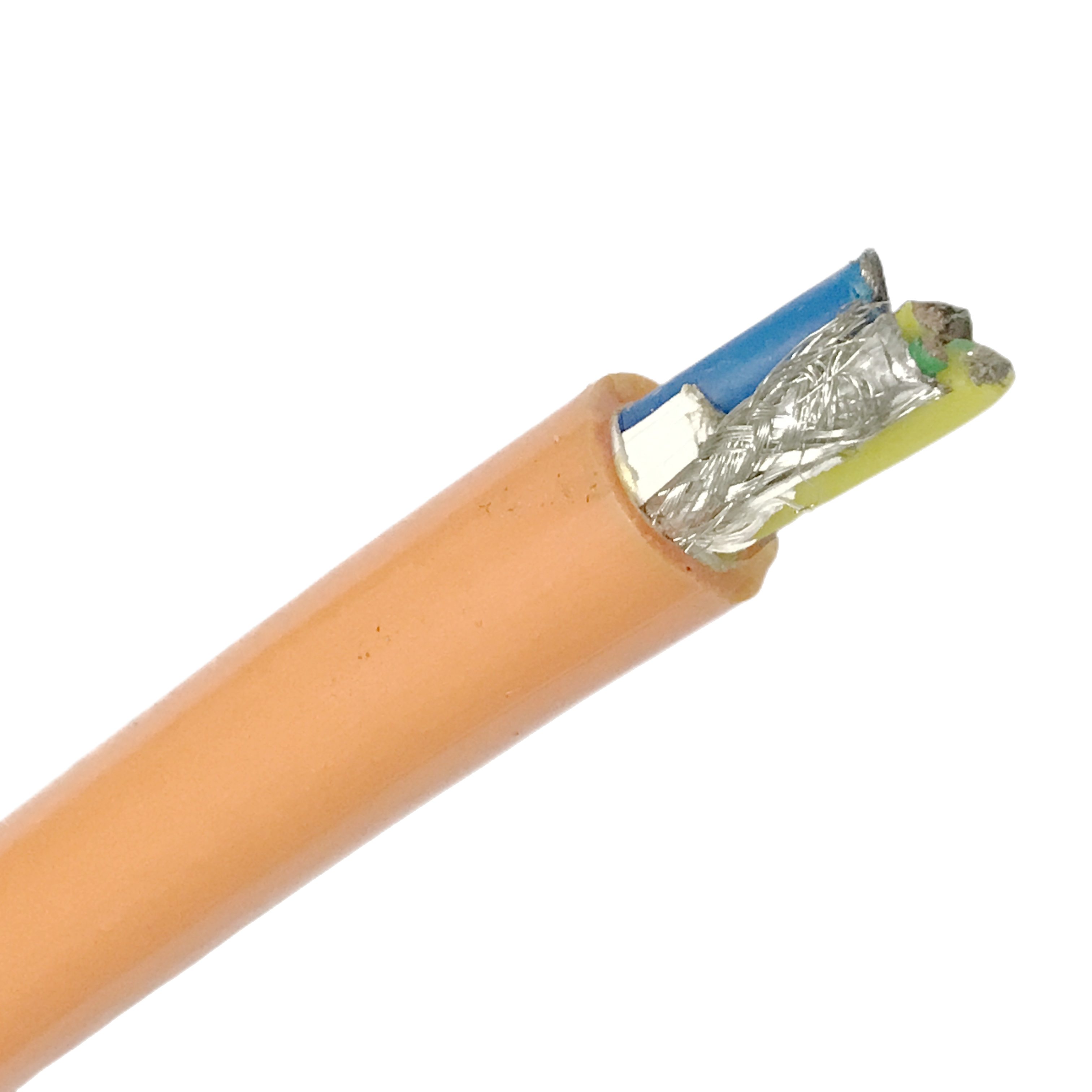
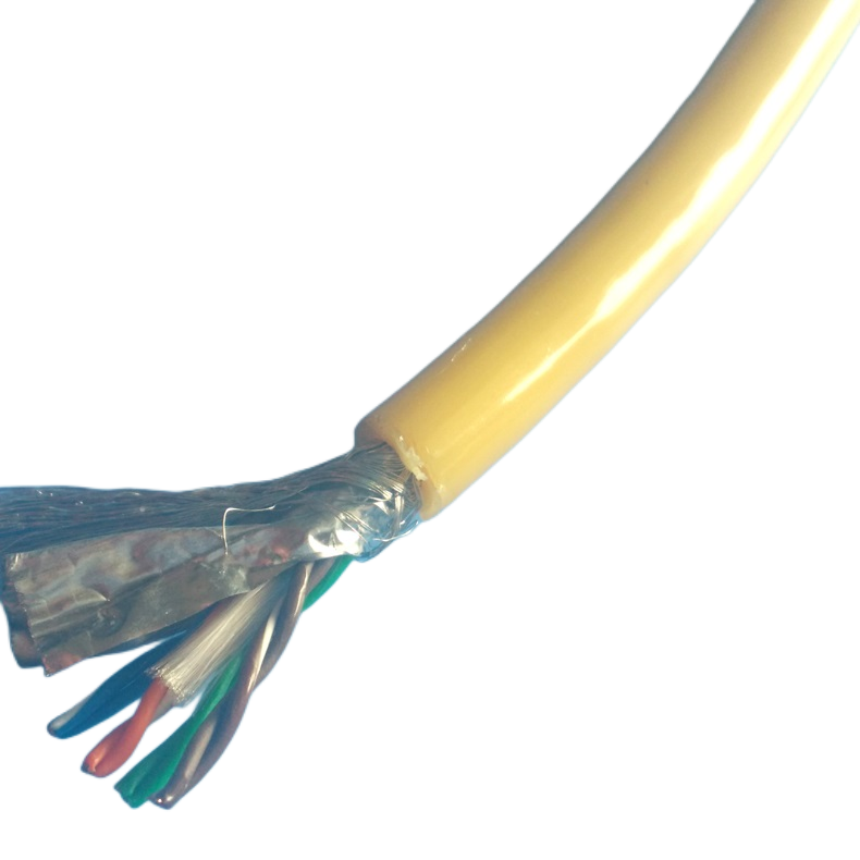
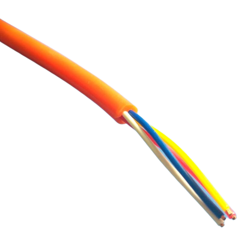
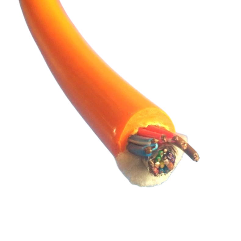
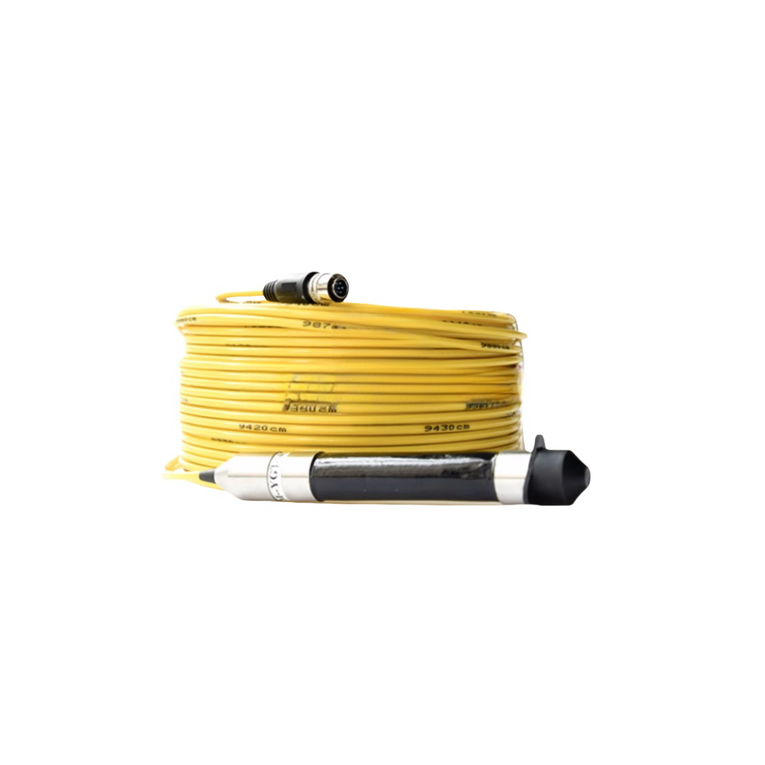
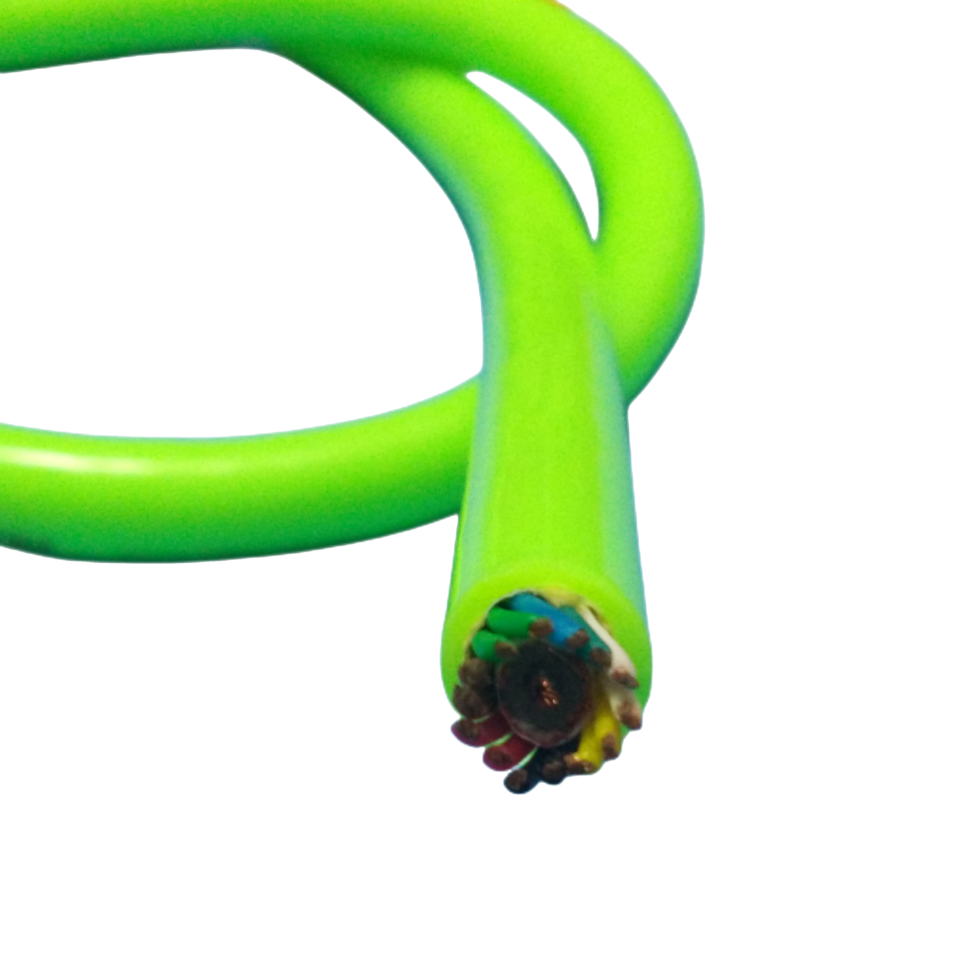
The seawater-resistant electro-optical composite cable in the RST-EOC series is built to prevent exactly this failure pattern. It combines copper power conductors for instrument power and control with single-mode or multimode optical fibres for high-bandwidth data — in a single cable that is engineered for long-duration deployment in seawater, tidal zones, splash zones, and dynamic marine environments where separate power and fibre cables would require two conduit runs, two penetrators, and two failure points.
Unlike generic ‘marine’ cables that apply a seawater-resistant jacket to a standard composite construction, the RST-EOC series is built from the inside out for marine duty: gel-filled loose-tube fibre elements for pressure equalisation, water-blocking compound at every interstice, and a jacket formulated specifically for resistance to seawater hydrolysis rather than general-purpose oil or chemical resistance.
■ How the Composite Architecture Works
An electro-optical composite cable carries two fundamentally different signal types — electrical power and photonic data — through a single cable jacket. The engineering challenge is that the physical requirements for optimal power cable design and optimal fibre cable design are in direct tension with each other. The RST-EOC series resolves this conflict layer by layer.
|
⚡ POWER Supply voltage 400V / 24VDC |
⚡ POWER OFC conductors 0.75–6 mm² |
⚡ POWER XLPE insulation Hi-pot tested |
⚡ POWER Instrument power & control signals |
|
Topside |
Cable jacket |
Water barrier |
Subsea end |
|
◈ FIBRE Tx: laser source OTDR test port |
◈ FIBRE SM/MM fibre Loose-tube gel-filled |
◈ FIBRE SAP tape + gel interstice fill |
◈ FIBRE Rx: sensor data high-bandwidth video |
Power path (copper) and fibre path (optical) are electrically and mechanically isolated within the same cable jacket. Screen segregation prevents 400V AC induction from degrading RS-485 / EtherCAT signal integrity on the data pairs that accompany the fibres.
■ When to Specify an Electro-Optical Composite vs. Separate Cables
The decision to use a composite electro-optical cable is driven by installation constraints, not just technical preference. The table below maps the conditions that push each direction — use it as a first-pass specification decision tool.
|
Condition |
Use Composite RST-EOC |
Use Separate Power + Fibre |
|
Number of conduit runs / penetrators available |
Single penetrator or conduit only → composite mandatory |
Two independent penetrators available → separate cables viable |
|
Subsea junction box space |
Limited internal volume → composite reduces connector count by 50% |
Large junction box with ample gland plate area |
|
Cable installation method |
Diver-installed, ROV-laid, J-tube pull-in → single cable is less risk |
Factory pre-terminated cable bundles in controlled conditions |
|
Fibre count requirement |
≤12 fibres → composite is cost-effective and compact |
>24 fibres → dedicated fibre cable is more practical |
|
Power level |
≤6 mm² per core (up to ~50 A) → composite handles it |
>16 mm² per core → power cable becomes too large for composite |
|
Fault finding and maintenance |
Single asset to test (one HiPot, one OTDR trace) → simpler |
Independent fault isolation of power vs. fibre faults |
|
Installation environment |
Splash zone, tidal, dynamic (cable moves) → single cable easier to secure |
Static burial, fixed trench, armoured duct |
|
Cost at short runs (<100 m) |
Composite is usually lower total installed cost |
Separate cables may be lower material cost at very short runs |
■ RST-EOC Series — Model Specifications
|
Model |
Fibre Type & Count |
Power Cores |
Control / Signal |
OD |
Depth Rating |
Armour |
Primary Application |
|
RST-EOC-S1 |
2× SM G.657.A1 |
2×1.5 mm² OFC |
4× 0.25 mm² screened pairs |
14.2 mm |
200 m |
None |
Tidal monitoring, quay instruments, shallow CCTV |
|
RST-EOC-S2 |
4× SM G.657.A1 |
2×2.5 mm² OFC |
4× 0.34 mm² + RS-485 pair |
16.0 mm |
500 m |
None |
Offshore platform sensors, wave buoy umbilical |
|
RST-EOC-M1 |
2× MM OM3 + 2× SM |
3×2.5 mm² OFC |
EtherCAT pair + 4 I/O pairs |
18.4 mm |
1,000 m |
Kevlar 3 kN |
ROV inspection tool, subsea junction box feed |
|
RST-EOC-M2 |
6× SM G.657.A1 |
3×4.0 mm² OFC |
4× 0.5 mm² + PROFIBUS pair |
20.8 mm |
2,000 m |
Kevlar 5 kN |
Subsea observatory node, pipeline monitoring |
|
RST-EOC-D1 |
8× SM G.657.A1 |
3×4.0 mm² OFC |
8× 0.5 mm² in 4 screened pairs |
23.2 mm |
3,000 m |
Kevlar 6 kN |
Deep sensor array, oceanographic mooring |
|
RST-EOC-A1 |
4× SM G.657.A1 |
4×2.5 mm² OFC |
4× 0.34 mm² screened |
24.0 mm |
1,000 m |
SS wire armour 10 kN |
Shore approach, surf zone, seabed drag risk |
|
RST-EOC-A2 |
8× SM G.657.A1 |
4×4.0 mm² OFC |
8× 0.5 mm² in 4 screened pairs |
28.5 mm |
3,000 m |
Double SS armour 18 kN |
Offshore wind SCADA trunk, heavy marine duty |
|
RST-EOC-DTS |
Distributed temp sensing (DTS) fibre + 2× SM data |
2×1.5 mm² OFC |
RS-485 interrogator pair |
16.8 mm |
500 m |
Optional |
Pipeline leak detection, subsea thermal mapping |
|
RST-EOC-OEM |
Custom 1–24 fibres |
Custom 0.5–10 mm² |
Custom protocol |
Per spec |
Per spec |
Per spec |
Offshore, naval, research custom projects |
SM = ITU-T G.657.A1 single-mode bend-insensitive. MM OM3 = IEC 60793-2-10 50/125 μm. All models longitudinally watertight. Depth ratings at 1.5× hydrostatic test factor. DTS model uses Raman-backscatter sensing fibre per IEC 61757-2-2.
■ Failure Mode Analysis — Why Marine Composite Cables Fail
Based on physical examination of failed cable samples submitted by offshore operators, subsea contractors, and monitoring system integrators over eight years of field support, the following failure modes account for over 90% of premature electro-optical composite cable replacements in marine environments. Each failure is preventable with correct specification.
|
Failure Mode |
Root Cause in Conventional Cable |
Field Symptom |
RST-EOC Design Response |
|
Fibre attenuation drift at depth |
Tight-buffered fibre construction: hydrostatic pressure is transmitted through the stiff buffer directly to the fibre cladding, inducing micro-bending loss. Attenuation increases nonlinearly below ~200 m and becomes severe below ~500 m. |
OTDR trace shows raised backscatter floor and attenuation spikes correlating with depth. Clears on cable recovery to surface. Mis-diagnosed as connector contamination. |
RST-EOC uses loose-tube gel-filled fibre elements: the fibre floats inside a gel-filled tube that equalises pressure. The gel transmits hydrostatic pressure uniformly without creating micro-bending strain. Validated to <0.10 dB/km additional attenuation at 1.5× rated depth. |
|
Seawater ingress at jacket micro-fractures |
Polyester PUR or PVC jacket develops micro-fractures from UV cycling, tidal flexing, or abrasion. Without longitudinal water-blocking, seawater tracks along the cable core via capillary action, reaching fibre and conductors hundreds of metres from the breach. |
Progressive insulation resistance drop on power cores. Fibre attenuation increase over weeks as moisture reaches the fibre bundle. HiPot test fails at a point remote from the visible jacket damage. |
Dual-barrier longitudinal water-blocking: water-blocking gel in all core interstices + SAP-coated water-blocking tape over the assembled bundle. A jacket breach is contained within <1 m of the breach point by tape swelling. Polyether PUR jacket resists micro-fracture formation vs. polyester PUR (no ester bond hydrolysis). |
|
Galvanic corrosion at power conductors |
Mixed-metal cable assemblies (copper conductors + galvanised steel armour) create galvanic couples in seawater electrolyte. Corrosion products from the armour migrate through poorly bonded jacket seams and deposit on conductor surfaces, increasing contact resistance at splices and connectors. |
Elevated contact resistance at subsea connectors. Partial or total loss of power channel months after installation. Armour wires show pitting corrosion on recovery. |
RST-EOC armoured models (A1, A2) use 316L stainless steel armour wire — galvanically compatible with copper in the seawater environment. Non-armoured models use no dissimilar metals. All armour terminations incorporate sacrificial zinc anodes in the cable grade design. |
|
Inter-layer electrical coupling (power-to-fibre EMI) |
400V AC power conductors without individual screening induce common-mode noise onto adjacent signal pairs through capacitive and inductive coupling. In long cable runs, induced noise can exceed the common-mode rejection ratio of RS-485 transceivers. |
RS-485 / Modbus communication errors increase with cable length and with power load. Error rate worsens as power current increases. Mis-diagnosed as transceiver failure or cable length limit. |
Three-tier screen isolation: each power core has individual XLPE insulation with defined dielectric strength; signal pairs are individually foil-screened with drain wire; an overall tinned copper braid screen covers the composite bundle before jacketing. Measured coupling attenuation >60 dB at 10 MHz. |
|
Optical connector contamination at wet-mate penetrators |
Factory-terminated wet-mate connectors that are subjected to splash-zone UV exposure develop seal degradation at the optical ferrule O-ring interface. Seawater enters the ferrule bore during connector cycling (mate/demate), depositing particulates on the fibre end-face. |
Sudden high insertion loss at subsea connector after 6–18 months. Loss is not recoverable by cleaning — the end-face is physically contaminated or micro-cracked. |
RST-EOC subsea connector assemblies (factory-terminated option) use double O-ring PEEK ferrule housings with UV-stable polyurethane overmould. Connector-end fibre stub is polished to IEC 61755-3-31 APC grade and individually dust-capped until deployment. |
■ Project References — RST-EOC Field Deployments
Customer names withheld at client request. Technical data verified and available under NDA for qualification purposes.
|
Project |
System |
Cable Deployed |
Engineering Challenge |
Status |
|
Tidal energy array, Scottish coastline |
Tidal turbine SCADA and power export monitoring, 18-month continuous deployment in 8 m/s peak tidal flow |
RST-EOC-A1: 4×SM + 4×2.5 mm² power + armour, 800 m run at 40 m depth |
Cable subject to continuous dynamic flexing in tidal current. Previous PVC-jacketed composite developed jacket fatigue cracking at 4 months. RST-EOC-A1 with polyether PUR jacket and SS wire armour reached 18-month deployment without jacket breach. |
Completed 2023. Repeat order placed for Phase 2. |
|
Offshore oil & gas platform, North Sea |
Subsea control module (SCM) power and communications feed, static installation, 320 m water depth |
RST-EOC-M2: 6×SM + 3×4.0 mm² + PROFIBUS pair, Kevlar 5 kN, 420 m total length |
Client required single-cable penetrator into SCM to replace existing dual-cable arrangement consuming both available gland positions. RST-EOC-M2 composite allowed full power and PROFIBUS data through one 25 mm penetrator. Pressure tested to 640 bar (1.5× rated depth) before shipment. |
Installed 2022. In service, no reported faults. |
|
Oceanographic mooring, western Pacific |
Distributed sensor mooring, 12 instrument nodes at depths from 200 m to 2,800 m, 3-year planned deployment |
RST-EOC-D1: 8×SM + 3×4.0 mm² + 8 signal pairs, 3,000 m rated, 3,200 m total pay-out |
Fibre attenuation budget required <0.5 dB total insertion loss across the 3,200 m run including connectors. Factory OTDR baseline: 0.18 dB/km at 1,550 nm. Pressure-vessel test at 45 MPa confirmed <0.08 dB/km additional attenuation — within budget. |
Deployed 2023. Year 1 OTDR data shows 0.21 dB/km at 1,550 nm — within specification. |
|
Offshore wind farm, Baltic Sea |
Array cable monitoring and SCADA data trunk between offshore substation and 14 turbine platforms |
RST-EOC-A2: 8×SM + 4×4.0 mm² + 8 signal pairs, double SS armour, 18 kN, 3,000 m rated |
Array cable monitoring required DTS (distributed temperature sensing) capability to detect insulation hot spots in the HV array cables. RST-EOC-A2 with DTS fibre channel ran alongside the main array cable in a shared J-tube. DTS interrogator at substation end resolves temperature to 1°C at 1 m spatial resolution across 4.2 km. |
Live monitoring since 2024 Q1. |
|
Aquaculture technology company, Norway |
Underwater camera and sensor pod array, 50 m depth, exposed to salmon farm bio-fouling and net-cleaning chemicals |
RST-EOC-S2: 4×SM + 2×2.5 mm² + RS-485 pair, 500 m rated, UV-stabilised jacket |
Previous polychloroprene-jacketed cable developed surface swelling and softening after 8 months of exposure to peracetic acid (PAA) net-cleaning agent. RST-EOC-S2 polyether PUR jacket showed no visible degradation after 12-month exposure test at 5% PAA concentration. |
Adopted as standard by client for all new cage installations. 2023–ongoing. |
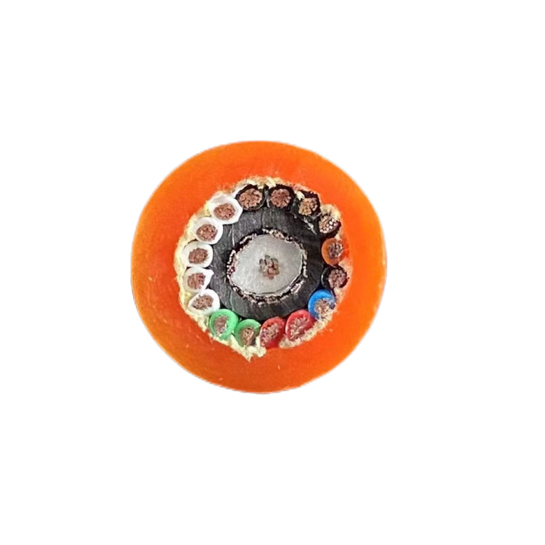
■ Construction — Integrated Electro-Optical Design
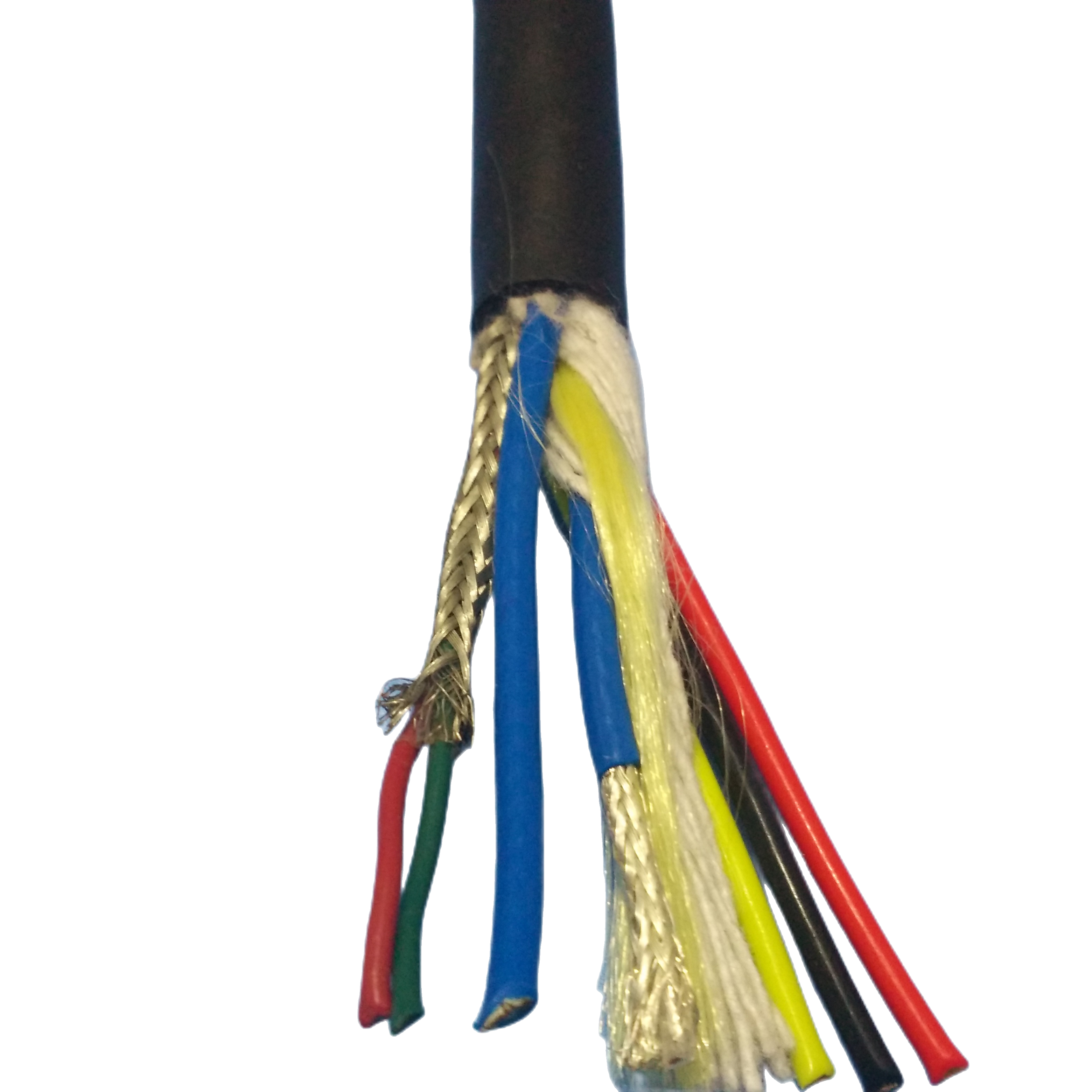
The construction of an electro-optical composite cable is not the sum of a power cable and a fibre cable placed side by side. It is a system in which the mechanical, thermal, and electromagnetic interactions between the two element types are engineered, not left to chance. The cross-section below describes each layer in terms of its function within the composite system.
|
Layer |
Specification |
Composite System Function |
|
Optical fibre elements — loose tube |
1–12 SM (G.657.A1) or MM (OM3/OM4) fibres per loose tube. Tube ID: 1.8–2.0 mm. Fibre OD: 0.25 mm. Tube filled with thixotropic petroleum gel. Secondary coating: PBT (polybutylene terephthalate), 850 μm OD. |
Loose tube geometry is the critical difference from tight-buffer construction: the fibre is free to move within the gel-filled tube, so hydrostatic pressure is transmitted as isotropic gel pressure rather than as bending strain on the fibre cladding. This is what prevents pressure-induced micro-bending attenuation at depth. PBT tube provides mechanical crush resistance that protects fibres during composite cabling and jacket extrusion. |
|
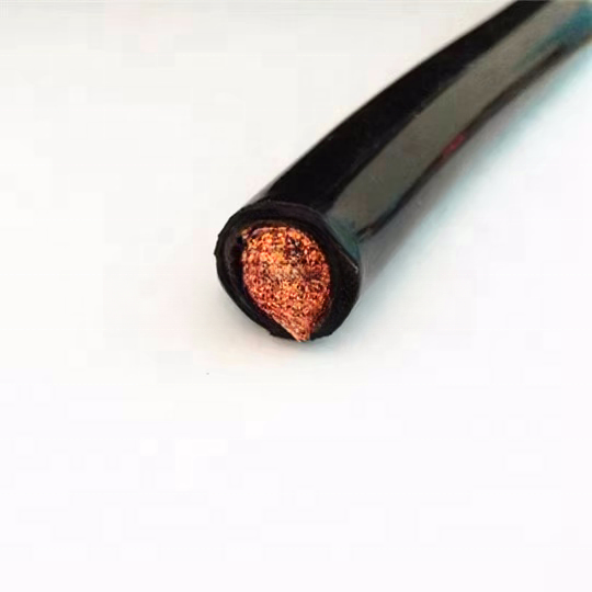
OFC power conductors |
Bare oxygen-free copper, IEC 60228 Class 5 (1.5–6 mm² standard; to 10 mm² OEM). XLPE insulation (90°C conductor temp rated), rated to 0.6/1 kV. Colour-coded per DIN VDE 0293. |
XLPE insulation is specified over PVC for two composite-specific reasons: (1) XLPE has lower dielectric loss tangent than PVC, reducing the capacitive coupling from power cores to adjacent signal pairs by approximately 40% at 400V AC 50 Hz; (2) XLPE maintains insulation integrity at the elevated conductor temperatures that occur when the cable is bundled with thermally insulating fibre elements in a sealed composite jacket. |
|
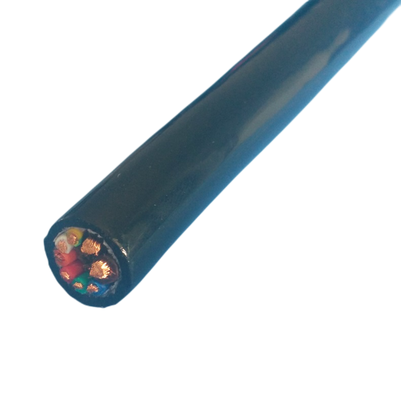
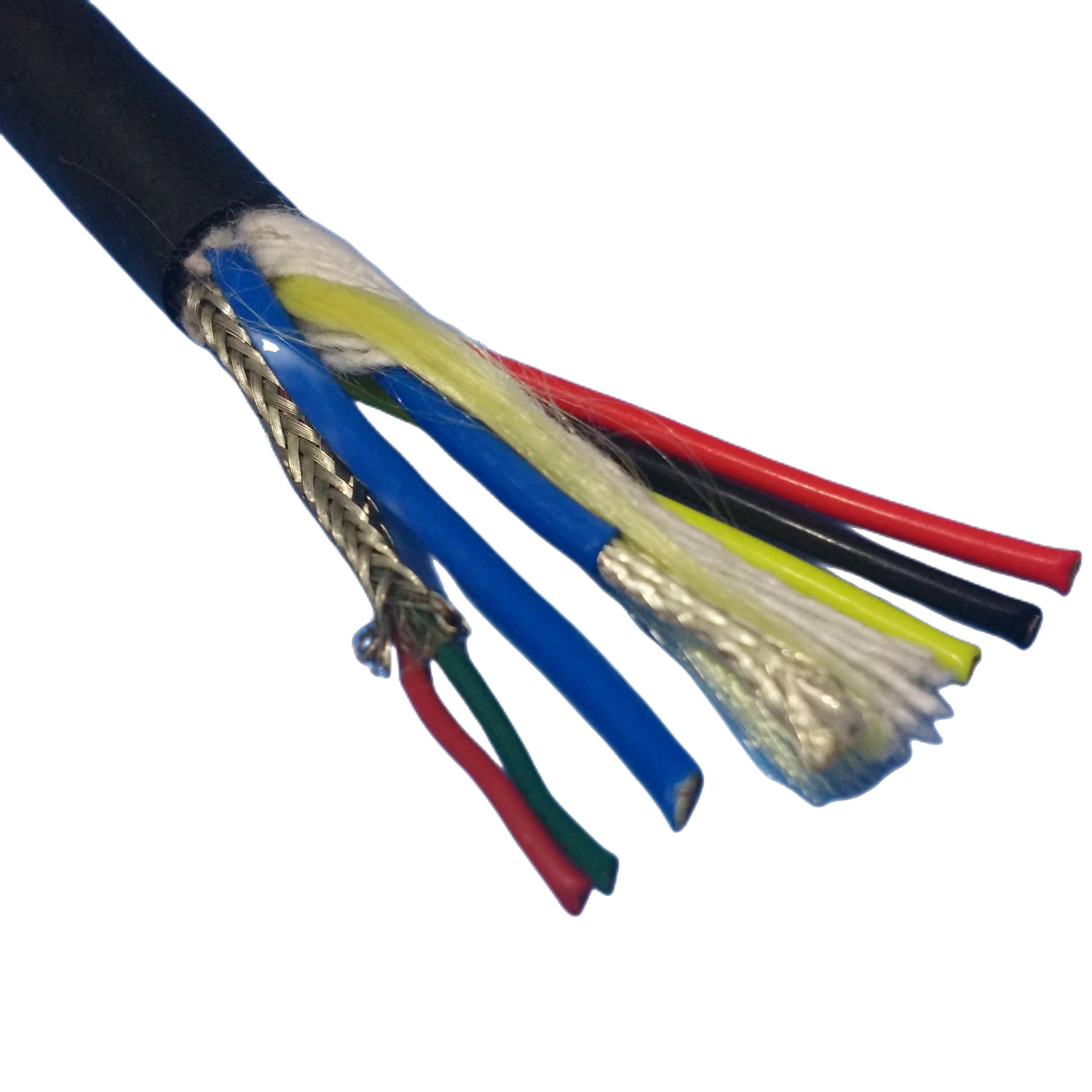
Signal / data pairs |
Individually foil-screened twisted pairs (Al-foil + drain wire, ≥95% coverage). Twist rate: 40–60 mm/turn. Conductor: 0.25–0.5 mm² OFC, Class 5. Supported protocols: RS-485, PROFIBUS DP, EtherCAT, Modbus RTU, CANbus. |
Individual screening (not overall screening only) provides inter-pair isolation that is essential in long marine cable runs: without individual screens, cross-talk between PROFIBUS and EtherCAT pairs at 10+ MHz can corrupt communication frames. The drain wire of each pair is connected to the overall shield at the topside end only (single-end shield bonding) to prevent circulating shield currents driven by the power conductors. |
|
Water-blocking system — interstice level |
Non-migrating petroleum-based water-blocking gel fills all air voids between elements, between tube bundles, and between tubes and cabling tape. SAP (super-absorbent polymer) coated water-blocking tape wound over assembled bundle as secondary barrier. |
Gel fills prevent capillary water migration along the cable interior if the outer jacket is breached. The SAP tape provides a secondary barrier: SAP absorbs up to 500× its weight in seawater and swells to seal the breach locally within seconds of water contact. Together these two barriers limit seawater migration to <0.5 m from any jacket breach point — the critical specification for subsea cables where full-length replacement is expensive. |
|
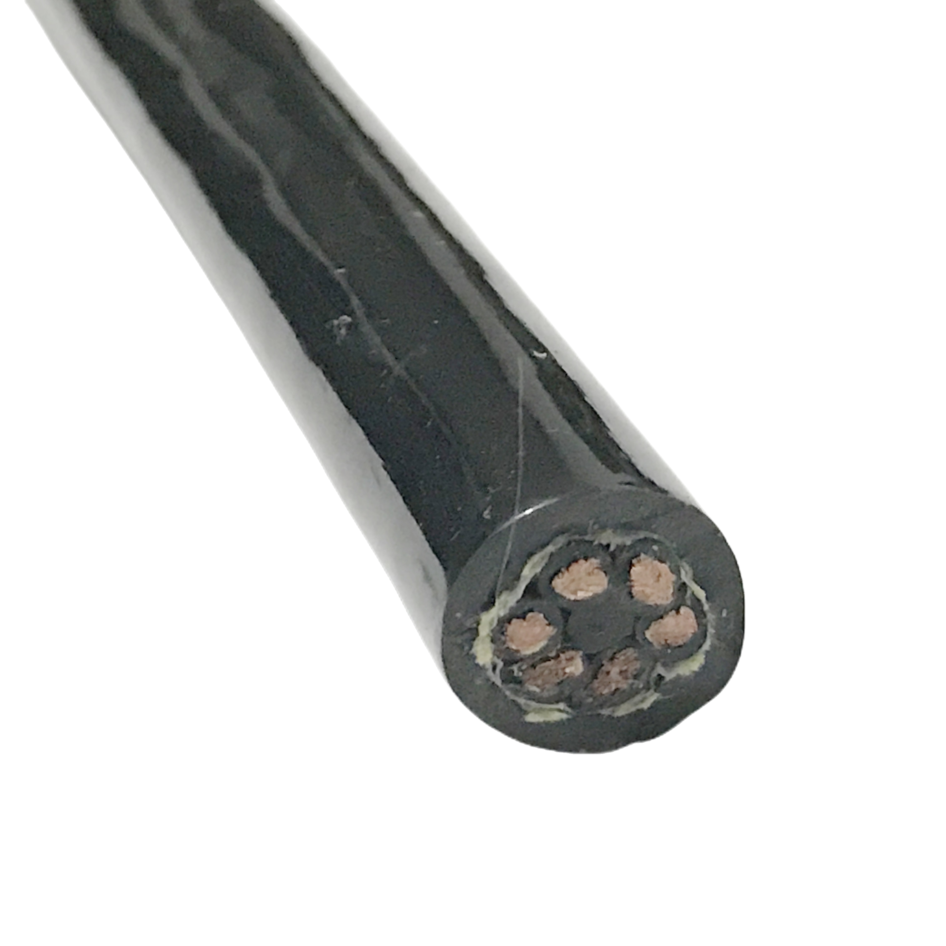
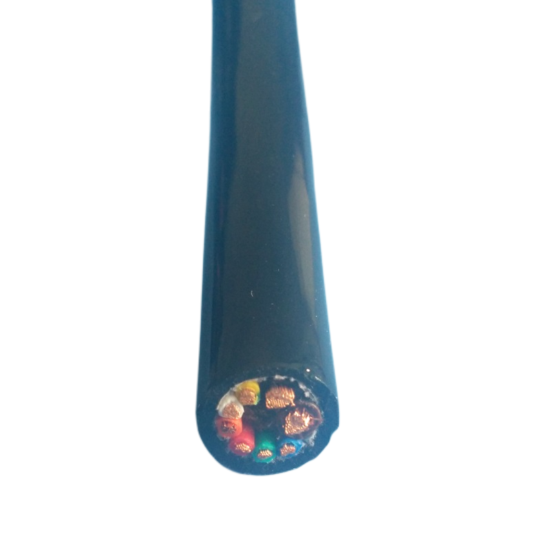
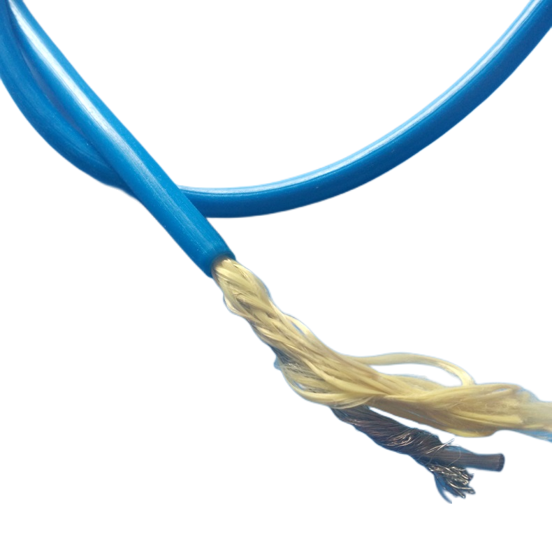
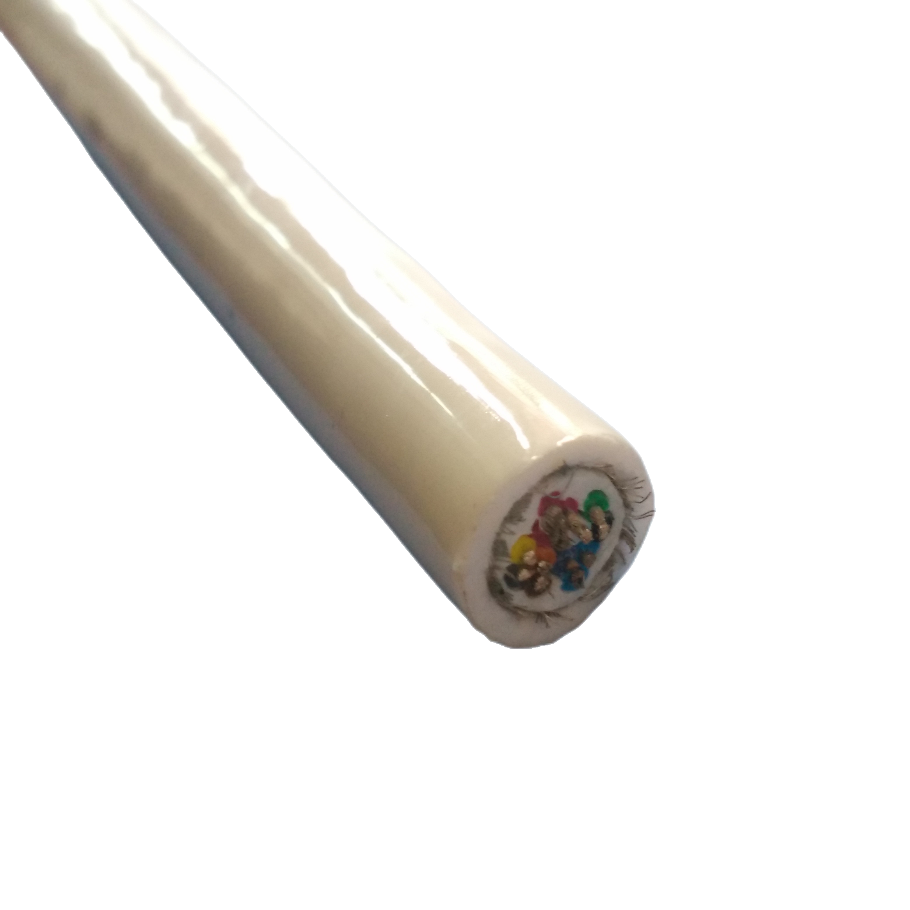
Element bundle geometry |
Optical elements positioned at cable centre (lowest mechanical stress zone in bending). Power cores positioned in outer ring around optical core. Signal pairs interleaved between power cores. Polypropylene filler cords achieve circular cross-section. Polyester fleece binder tape over assembled bundle. |
The positioning of optical elements at the neutral axis of the cable cross-section is not accidental: the neutral axis experiences the lowest bending strain in any cable bend. This placement minimises the incremental attenuation that results from dynamic bending of the composite cable — measured as <0.02 dB/km per 1,000 bend cycles at 10× OD in RST-EOC test data. |
|
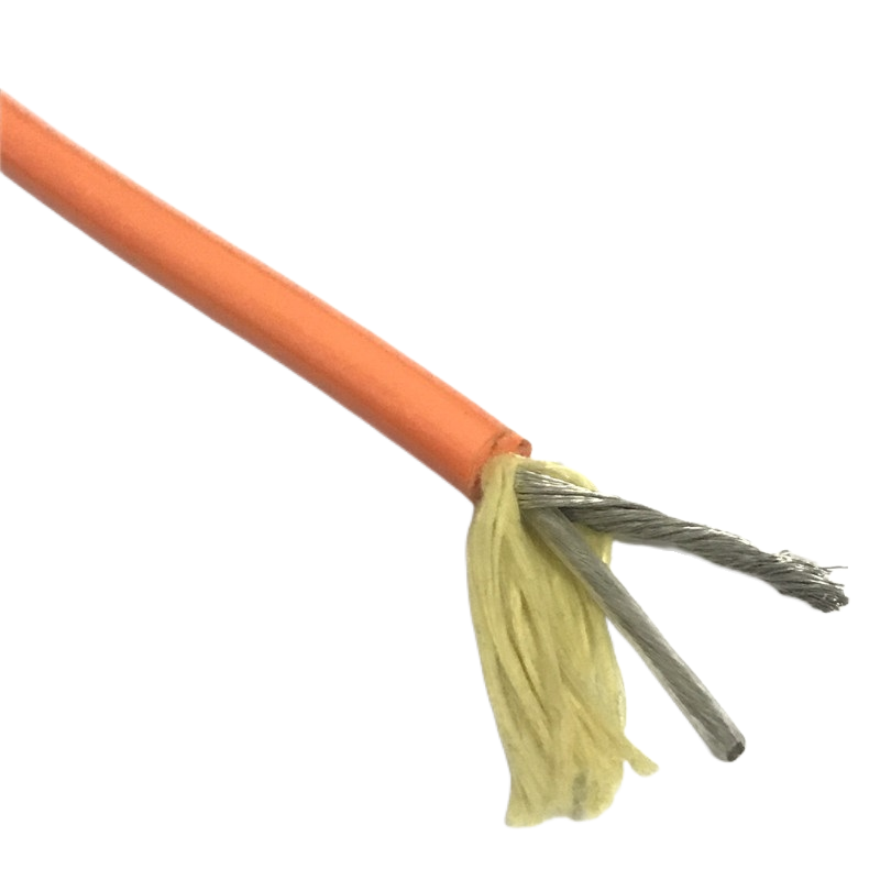
Armour (A1, A2 models) |
RST-EOC-A1: single layer 316L stainless steel wire, 0.9 mm diameter, helical lay, 55° lay angle. RST-EOC-A2: double contra-wound SS wire layers. Breaking load: 10 kN (A1) / 18 kN (A2). |
316L stainless steel is specified over galvanised carbon steel for marine composites because the galvanic potential difference between galvanised steel and copper in seawater is 0.4–0.6 V — sufficient to drive measurable corrosion current at any point where the jacket is breached. 316L stainless is galvanically closer to copper (0.05–0.10 V difference), dramatically reducing corrosion risk at jacket breach points. |
|
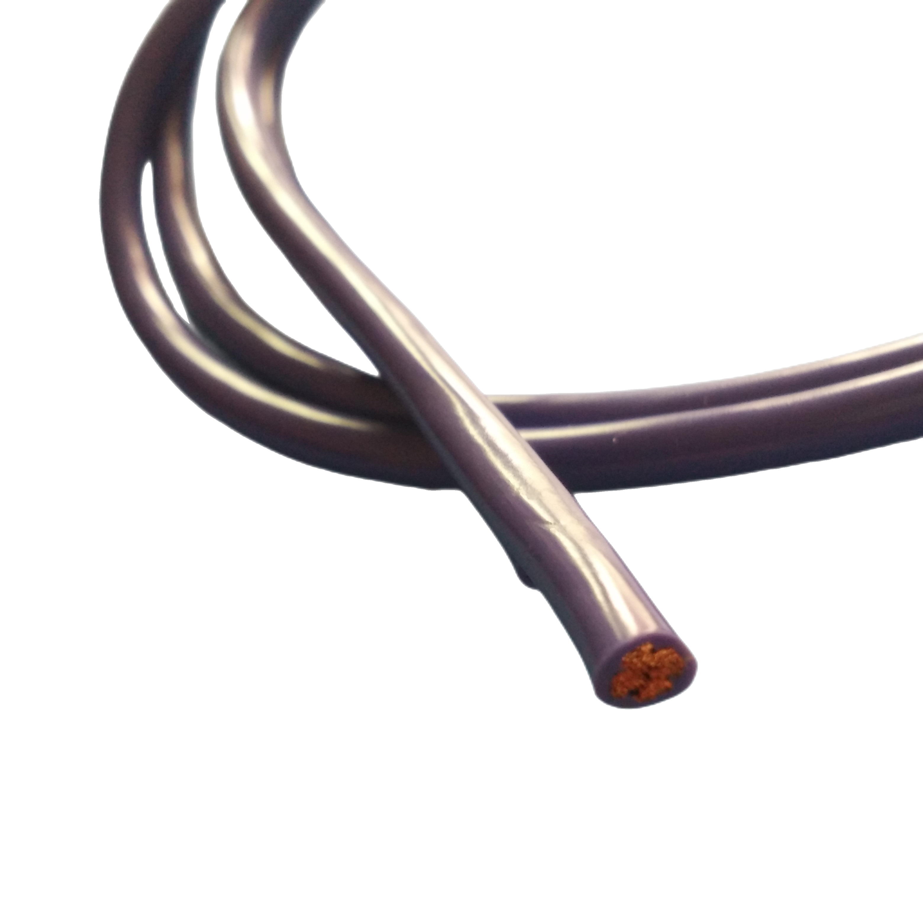
Outer jacket — polyether PUR |
Polyether-based TPU, Shore A 83±3 (softer grade for marine dynamic applications). Tensile strength ≥48 MPa. Elongation ≥380%. Taber abrasion CS-17 1 kg: ≥350 cycles. Seawater hydrolysis: no degradation after 5,000 h at 23°C (ISO 175). UV resistance: 1,000 h xenon arc, ≤80% tensile retention. |
Shore A 83 is slightly softer than the reel-cable grade (88) used in RST-RC: composite marine cables experience more complex multi-axis bending (tidal flex, ROV cable loops, installation pull-in) than reel cables, and the softer compound provides better fatigue resistance in variable-direction bending. The hydrolysis test (5,000 h ISO 175) is the design-qualification test that distinguishes polyether from polyester PUR — test data available for customer review. |
■ Optical Performance Specifications
Optical performance in a composite cable is not identical to the same fibre type in a standalone fibre cable. The mechanical environment of the composite — shared jacketing with power conductors, multi-layer cabling geometry, and service in dynamic marine conditions — imposes additional mechanical loads on the fibre that must be accounted for in the link budget. The specifications below reflect RST-EOC performance in the composite installation, not bare-fibre data sheet values.
|
Parameter |
Single-Mode G.657.A1 |
Multimode OM3 |
Test Condition / Standard |
|
Attenuation @ 1310 nm |
≤0.36 dB/km |
N/A |
IEC 60793-2-50; factory measurement |
|
Attenuation @ 1550 nm |
≤0.22 dB/km |
N/A |
IEC 60793-2-50; factory measurement |
|
Attenuation @ 850 nm |
N/A |
≤3.0 dB/km |
IEC 60793-2-10 |
|
Attenuation @ 1300 nm |
N/A |
≤1.0 dB/km |
IEC 60793-2-10 |
|
Additional attenuation at rated depth (1.5× test) |
≤0.10 dB/km |
≤0.15 dB/km |
Pressure vessel per IEC 60794-1-2 F12B |
|
Additional attenuation after 1,000 bending cycles (10× OD) |
≤0.02 dB/km |
≤0.05 dB/km |
IEC 60794-1-2 Method E10; in-composite test |
|
Minimum bend radius (long-term installation) |
30 mm (G.657.A1 rated) |
50 mm |
IEC 60793-2-50 / IEC 60793-2-10 |
|
Minimum bend radius (short-term, cable handling) |
15 mm |
25 mm |
IEC 60794-1-2 Method E4 |
|
Polarisation mode dispersion (SMF) |
≤0.04 ps/√km |
N/A |
IEC 60793-2-50 |
|
Chromatic dispersion @ 1550 nm |
≤17 ps/(nm·km) |
N/A |
IEC 60793-2-50 |
|
OTDR trace supplied |
Yes (1310 + 1550 nm per fibre) |
Yes (850 nm) |
Per drum, included in shipment documentation |
|
Fibre end-face inspection |
IEC 61755-3-31 APC (if factory-terminated) |
IEC 61755-3-31 PC |
Per connector, with image record |
■ Electrical & Mechanical Parameters
Electrical — Power Cores
|
Parameter |
Value |
Reference |
|
Rated voltage (power cores) |
300/500 V (standard); 0.6/1 kV (D1, A2 models) |
IEC 60502-1 |
|
Test voltage (HiPot) |
2,000 V AC / 5 min (300/500 V); 3,500 V AC / 5 min (0.6/1 kV) |
IEC 60502-1 Cl.17 |
|
Insulation resistance |
≥500 MΩ·km (power cores); ≥1,000 MΩ·km (signal pairs) |
IEC 60502-1 Cl.18 |
|
Max. conductor operating temp |
+90°C (XLPE insulation); conductor temp in composite limited to +75°C continuous |
IEC 60502-1 |
|
Max. operating current (in composite jacket) |
Per IEC 60364-5-52, derating factor 0.75 for composite bundle |
IEC 60364-5-52 |
Electrical — Signal / Data Pairs
|
Parameter |
Value |
Reference |
|
Characteristic impedance |
120 Ω ± 10 Ω (RS-485 / PROFIBUS); 100 Ω ± 5 Ω (EtherCAT) |
IEC 61156-5 |
|
Pair screening coverage |
≥95% (Al-foil bonded); drain wire 0.25 mm² OFC |
IEC 61156-5 |
|
NEXT (10 MHz) |
≤−42 dB (screened pairs in composite) |
IEC 61156-5 |
|
Power-to-signal coupling attenuation |
≥60 dB at 400V AC 50 Hz with 10× OD bending |
Internal composite EMC test |
|
Max. Modbus / RS-485 run length |
4,000 m (at 9,600 baud with 120 Ω termination) |
EIA-485 / TIA-485 |
|
EtherCAT delay per metre |
≤5.5 ns/m (Cat 5e equivalent pair) |
ETG.1600 |
Mechanical & Environmental
|
Parameter |
Value |
Standard |
|
Working depth (rated) |
200 m / 500 m / 1,000 m / 2,000 m / 3,000 m per model |
Pressure test 1.5× per IEC 60794-1-2 F12B |
|
Minimum bending radius (dynamic service) |
10× OD (non-armoured); 15× OD (armoured) |
IEC 60794-1-2 Method E10 |
|
Minimum bending radius (static) |
5× OD |
— |
|
Tensile strength (Kevlar models) |
3 kN / 5 kN / 6 kN; tested to 1.5× |
ASTM D7269; load-cell per drum |
|
Tensile strength (armoured) |
10 kN (A1) / 18 kN (A2); tested to 1.5× |
IEC 60502-4 |
|
Jacket tensile strength |
≥48 MPa |
ISO 37 |
|
Jacket elongation at break |
≥380% |
ISO 37 |
|
Jacket Shore A hardness |
83 ± 3 |
ISO 868 |
|
Jacket abrasion (Taber CS-17, 1 kg) |
≥350 cycles |
ISO 9352 |
|
Seawater hydrolysis resistance |
No degradation after 5,000 h at 23°C |
ISO 175 |
|
Chemical resistance (PAA 5%) |
No surface degradation after 1,000 h at 23°C |
Internal immersion test |
|
Operating temperature |
−40°C to +80°C (surface); 0°C to +4°C (seabed) |
IEC 60811-501 |
|
UV resistance |
1,000 h xenon arc; ≤80% tensile retention |
IEC 60811-401 |
|
Longitudinal watertightness |
Seawater migration ≤0.5 m from breach point |
IEC 60794-1-2 Method F5B |
|
Flame retardancy |
IEC 60332-1 (single wire, on request) |
IEC 60332-1 |
|
Saltwater galvanic compatibility (armour) |
316L SS armour; <0.1 V galvanic potential vs copper |
ASTM G82 |
■ Installation Notes for Marine Composite Cables
Composite cables require installation practice that respects both the power cable minimum bend radius and the fibre cable minimum bend radius simultaneously — the more restrictive of the two governs. The notes below address the installation steps where composite cables are most commonly damaged.
|
Installation Step |
Minimum Radius / Tension |
Common Error |
Correct Practice |
|
J-tube pull-in |
Bend radius at J-tube bell mouth: ≥10× OD (non-armoured) or ≥15× OD (armoured). Max. pull tension: Kevlar models ≤80% of rated tensile load; armoured ≤70%. |
Using a standard pulling grip that grips the outer jacket only — jacket elongates under pull tension, transferring load to conductors and fibres rather than to the tensile member. |
Use a purpose-designed cable grip that clamps the armour wires (armoured models) or the Kevlar braid (Kevlar models) directly. Supply grip design drawing to Rousheng at order stage for factory pre-attachment option. |
|
Dynamic hanging loop (splash zone) |
Cable loop at the transition from static submerged section to dynamic tidal zone: radius ≥12× OD. Cleat spacing: ≤OD × 30 on the static section above the loop. |
Cleating the cable too close to the dynamic zone transition point, concentrating flex cycles at a single cable cross-section. |
Provide a minimum 2 m free loop at the tidal transition. Protect the loop with a spiral armour wrap or anti-abrasion boot where it contacts the structure. |
|
Subsea connector mating |
Connector mating torque per manufacturer specification. Inspect O-rings with 10× loupe before every mate/demate cycle. |
Mating wet-mate connectors with contaminated or scratched O-rings. A single fibre end-face particle causes >0.5 dB insertion loss that cannot be field-cleaned. |
Inspect, clean, and re-grease O-rings at every mate cycle. For factory-terminated RST-EOC cables, maintain the protective dust cap on the connector until the moment of mating. |
|
Deck handling in low temperatures |
Minimum handling temperature: −10°C (standard PUR jacket). Do not bend cable around deck fittings or winch drums below −10°C without pre-warming. |
Bending composite cable in sub-zero conditions causes fibre micro-cracks at the point of maximum curvature. These are detectable by OTDR as a permanent attenuation event. |
Store cable drums in a heated compartment at ≥+5°C for 4 hours before deck handling in sub-zero conditions. For Arctic operations, specify the RST-EOC low-temperature jacket compound (rated to −40°C dynamic handling). |
■ FAQ — Marine Engineers & Subsea System Integrators
Q1: Can I use the same cable for both the tidal zone (dynamic) and the static subsea section, or do I need different cable types at the transition?
A composite cable rated for the dynamic tidal section will also work in the static subsea section, but the reverse is not true: a cable designed only for static subsea (typically tighter jacket compound, optimised for minimum OD rather than flex life) will fail prematurely in the tidal dynamic section. For most marine monitoring installations, Rousheng recommends a single continuous cable type from topside to instrument — this eliminates the subsea splice required at a transition point, which is always the highest-risk point in a long-duration deployment. The RST-EOC-S2 and RST-EOC-M1 models are specified for both dynamic and static duty simultaneously.
Q2: What is the link budget impact of using a composite cable versus a standalone fibre cable?
The link budget penalty from the composite construction has two components. First, the mechanical component: in-composite dynamic bending adds approximately 0.02 dB/km per 1,000 bend cycles at 10× OD — negligible for static or low-cycle installations, and <0.1 dB/km over a 5-year tidal monitoring deployment at typical cycle rates. Second, the pressure component: at rated depth with loose-tube gel-fill construction, additional attenuation is <0.10 dB/km at 1.5× hydrostatic test pressure. For a 500 m run at 300 m depth with 4 dB power budget (standard 850 nm multimode link), the composite penalty is 0.10 + 0.05 = 0.15 dB — well within the power budget. For system designers who need formal link budget calculations, our engineering team can provide a run-specific analysis based on your transceiver specifications and cable model selection.
Q3: Why is single-end shield bonding specified for signal pairs, and what happens if both ends are bonded?
In a composite cable carrying 400V AC power conductors alongside screened signal pairs, the power conductors induce a common-mode voltage on the signal pair screens via capacitive coupling. If both ends of a signal pair screen are bonded to earth, this common-mode voltage drives a circulating current in the screen. In a long cable run, this screen current can be several milliamps — enough to saturate the ferrite cores in RS-485 transceivers and cause communication errors. Single-end bonding (topside end only) presents the screen as a high impedance path for the common-mode current while still providing electrostatic shielding effectiveness. The drain wire is routed to the cable gland earth at the topside and left unterminated (but not floating — it is taped back against the insulation) at the subsea end. This is specified in IEC 61000-5-2 for screened cable installations in mixed power and signal environments.
Q4: How do I specify the correct fibre count for a subsea monitoring array with planned future expansion?
Specify at least 2× the number of fibres currently required, up to the next standard configuration in the RST-EOC model range. Spare fibres cost approximately 8–12% of the cable unit price for the additional fibre tubes, but avoid the need for a new cable installation if the monitoring array is expanded. This is a universally recommended practice in subsea infrastructure because the cable installation cost (vessel time, diving, ROV) typically exceeds the cable material cost by 5–10× in offshore environments. Any spare fibres should be terminated at both ends with dust-capped connectors (or pigtails at a patch panel) and OTDR-tested at commissioning to confirm they are available for future use.
Q5: What is DTS (distributed temperature sensing) and when is it combined with a composite electro-optical cable?
DTS uses the Raman backscatter signal in a sensing optical fibre to measure temperature at every point along the fibre simultaneously — the equivalent of placing a thermometer at every metre of the cable route. When a composite cable carries both DTS sensing fibre and conventional data fibres alongside power conductors, it can serve as both the power supply and control link to a subsea instrument and as a distributed temperature sensor along its entire run. This combination is most valuable in subsea pipeline monitoring (detecting localised heating from flow assurance issues), offshore wind array cable monitoring (detecting insulation overheating in buried cable sections), and fish farm temperature profiling. The RST-EOC-DTS model integrates Raman-backscatter sensing fibre (per IEC 61757-2-2), conventional SM data fibres, and power cores in a single cable. DTS spatial resolution is 1 m; temperature resolution is ±1°C at up to 8 km sensing range with a standard interrogator.
Q6: What documentation is supplied with each RST-EOC cable drum?
Standard documentation per drum: (1) Dimensional inspection report — OD at 5 measurement points along the drum length; (2) HiPot test certificate — all power cores and signal pairs tested to rated voltage, pass/fail recorded; (3) Insulation resistance certificate — measured IR value for each core and pair at 500 VDC; (4) Conductor resistance certificate — measured DC resistance per core, compared against IEC 60228 maximum; (5) OTDR trace printout — all fibres at 1310 nm and 1550 nm (SM) or 850 nm (MM), with event table; (6) Pressure test certificate — for models rated >200 m, certificate of hydrostatic pressure test at 1.5× rated depth in Rousheng’s hyperbaric chamber; (7) RoHS 2 / REACH declaration; (8) Material certificate for jacket compound (polyether PUR grade confirmation). Optional (on request): third-party laboratory test report from CNAS-accredited facility; ISO 175 hydrolysis test data for jacket material batch.
■ Manufacturer Credentials — Shanghai Rousheng Marine Cable
|
Subsea production facilities In-house hyperbaric test chamber to 600 bar (6,000 m equivalent) Optical splicing laboratory: SM and MM fibre, fusion and mechanical splice OTDR measurement suite: Yokogawa AQ7280 (SM) and AQ7282 (MM) Composite extrusion line: simultaneous co-extrusion of gel-fill tube and jacket layers 100% HiPot + IR test on all copper cores and signal pairs per drum Wet-mate connector assembly and test facility for factory-terminated orders |
Certifications & approvals ISO 9001:2015 quality management CE marking — LVD Directive 2014/35/EU RoHS 2 / REACH SVHC compliance DNV / Bureau Veritas type approval (on request) CNAS-accredited lab reports available IEC 60794-1-2 pressure test certification: NIST-traceable calibration Failure analysis service: written report on submitted failed cable samples |
Rousheng’s subsea composite cable engineering team reviews every project enquiry against the failure mode analysis in Section 5 of this page before issuing a model recommendation. Where the application profile suggests a failure mode that a standard RST-EOC model does not fully address, we identify the gap in writing and propose either a model upgrade or an OEM modification before the customer commits to an order. We consider this pre-sale engineering review to be as important as the cable itself.
■ Request a Technical Proposal or Cable Sample
|
Contact Email: Jerry@rstlkable.com Phone: +86-021-50759965 Mobile: +86-13482197396 Address: No. 2591 Fengzhe Road, Fengxian District, Shanghai, China Technical proposal within 24 hr. Full documentation package (OTDR + HiPot + IR + pressure test certificate) with every order. |
What to include in your enquiry 1. Operating depth (m) and deployment duration (years) 2. Power requirement at subsea end: voltage (V), current (A) 3. Fibre count and type (SM, MM, DTS, or mixed) 4. Signal protocols required (RS-485, EtherCAT, PROFIBUS, etc.) 5. Cable run length and installation method (J-tube, direct burial, dynamic hang) 6. Environmental exposures: tidal dynamic, UV, chemical (specify agent) We return a model recommendation, link budget calculation, and VD analysis with every technical enquiry. |