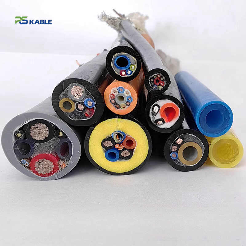
Reeling Cable with Air Hose | Hybrid Power, Signal & Pneumatic Cable for Drum Systems
This drum-compatible cable integrates power, signal/Ethernet, and one or two pneumatic hoses in a single PUR or LSZH jacket for compact, reliable performance.
Key Benefits:
✅ All-in-one power, data, and air transmission
✅ Rated ≥1,000,000 drum cycles, up to 20 bar
✅ Strong, flexible design for reeling systems
✅ Ideal for cranes, gantries, hoists, and parking systems
Custom designs and replacement solutions available.
Reeling Cable with Air Hose | Hybrid Power, Signal & Pneumatic Cable for Drum Systems
|
Combined elements |
Max hose pressure |
Drum cycle rating |
Hose bore range |
Outer jacket |
|
Power + Signal + Air |
20 bar |
≥ 1,000,000 |
6 – 16 mm ID |
PUR / LSZH |
|
All in one drum lay |
PU bore, dual-hose option |
Full extension/retraction |
Standard & ETO |
−30 °C to +90 °C |
Replacing a Failed Drum Cable-and-Hose Assembly: Start Here
If you have arrived at this page because an existing reeling cable with air hose has failed on a crane, gantry, or hoist and you need a direct replacement, the three parameters below determine compatibility with your existing drum. Measure them before requesting a quotation — they allow Rousheng’s engineering team to confirm a drop-in replacement in a single exchange rather than a multi-step specification process.
|
Measure this |
How to measure |
Why it determines compatibility |
|
Existing cable OD |
Vernier calliper across the outer jacket at a straight, unwound section. Measure at three points along 500 mm and take the mean. |
The drum groove pitch is machined to fit the original cable OD ± 0.5 mm. A replacement cable with OD more than 0.8 mm larger than the groove width will not seat and will cross-wind. A replacement more than 1.5 mm smaller will rattle and abrade against the groove flanks. |
|
Air fitting type and hose OD |
Photograph the free-end hose termination. Note whether it is a push-in stub (measure OD), a BSP threaded fitting (count turns), or an NPT fitting. |
Push-in fittings are OD-specific: a 6 mm OD tube requires a 6 mm collet. BSP and NPT are not interchangeable. Specifying the wrong fitting at order adds 2–3 weeks for re-termination. |
|
Rotary union port size |
Locate the rotary air union at the drum spindle centre. Measure or note the thread size on the union inlet port (typically stamped on the body). |
The replacement cable hose bore ID must be sized to maintain adequate flow at the union’s rated port Cv. A bore ID downgrade — even within the available standard range — reduces available flow at the tool end and may cause actuator timing errors. |
|
RETROFIT NOTE |
Rousheng holds drum-groove dimensional records for major European and Asian crane OEM drum models. If your drum is from a known manufacturer, provide the drum model number and we can confirm cable OD compatibility from our records without requiring a site measurement. For drums with no model identification, a dimensional drawing or photograph with a scale reference is sufficient. |
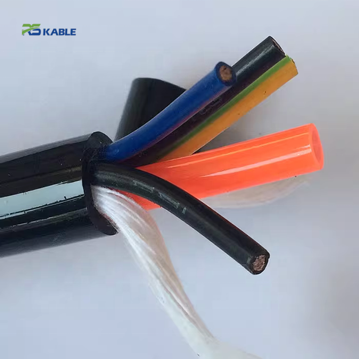
What a Reeling Cable with Integrated Air Hose Delivers
Conventional drum system design for equipment requiring electrical power, control signals, and compressed air uses three separate reeling assemblies — one cable drum for power, a second for signal, a third for the pneumatic hose. Each carries its own motor or spring, its own slip ring stack, and its own rotary union. In crane installations, this multiplies the number of maintenance-accessible components on the bridge end truck and, more consequentially, multiplies the number of independent failure modes that cause full crane downtime.
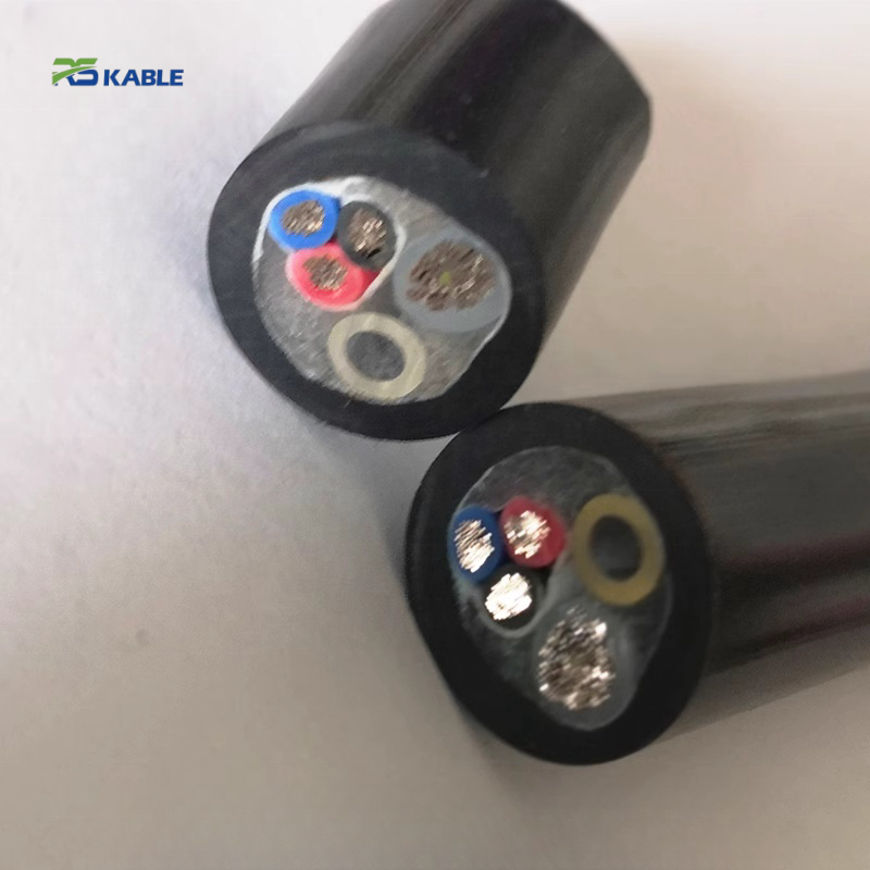
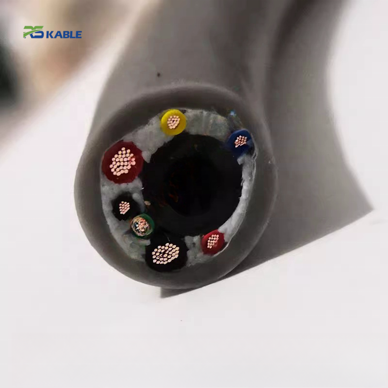
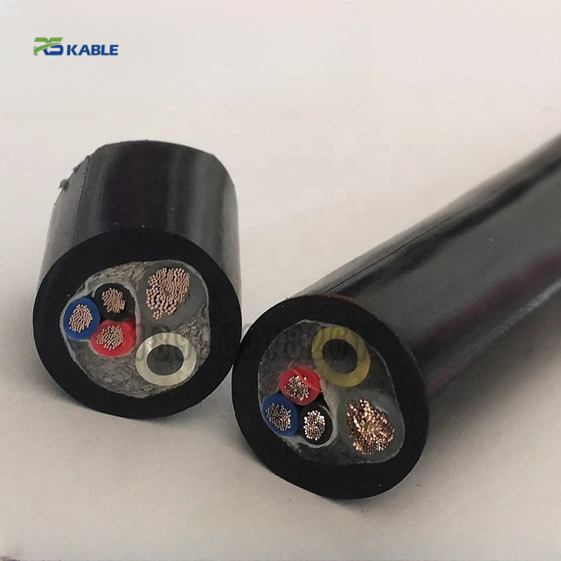
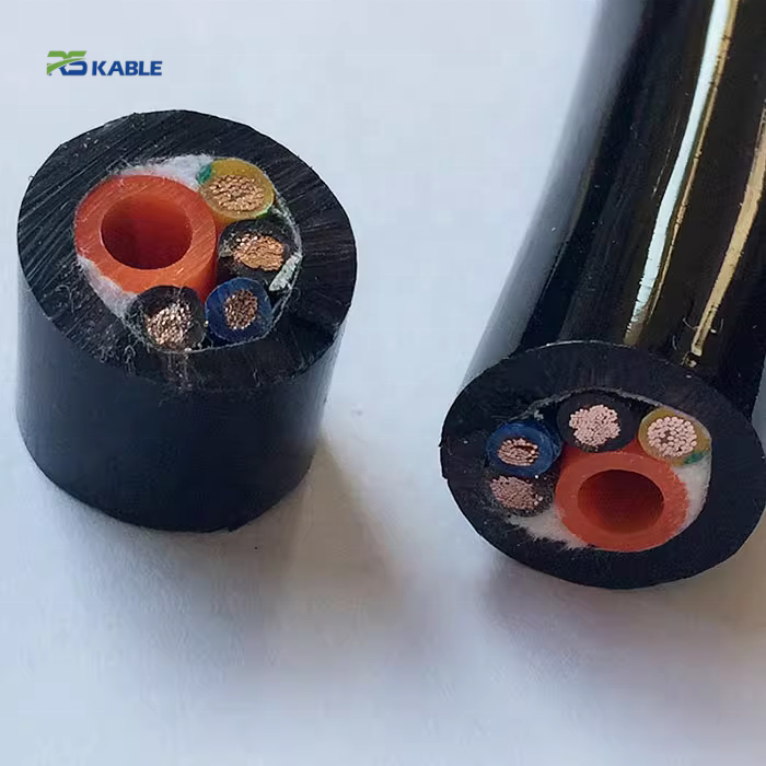
The RST-RH reeling cable with air hose consolidates this into a single drum run. Power conductors, shielded signal pairs or Ethernet cores, and one or two polyurethane pneumatic hose bores are co-jacketed in a single outer PUR sheath, wound on one drum, and served by one slip ring stack with one rotary air union at the drum core. The result is not simply a convenience — it is a reliability improvement. Fewer rotating interfaces means fewer seal failure points, fewer electrical contact wear paths, and fewer synchronisation requirements between drum drives.
The engineering challenge this product solves — and why a simple parallel bundle of cable and hose on a shared drum is not an equivalent solution — is documented in the construction section below.
RST-RH Series Product Matrix
Model reference, standard configurations, and validated performance parameters. All OD values are production measurements, not design nominals. ETO suffix denotes engineered-to-order; lead time 4–6 weeks from confirmed specification.
|
Model |
Power cores |
Signal / data |
Hose(s) |
Bore ID (mm) |
Max bar |
OD (mm) |
Flex life / jacket |
|
RST-RH-110 |
3 × 1.5 mm² |
4 × 0.5 mm² ctrl |
1 × PU |
6 |
12 |
16.0 ±0.5 |
≥1M · PUR |
|
RST-RH-120 |
3 × 2.5 mm² |
4 × 0.5 mm² ctrl |
1 × PU |
8 |
16 |
18.5 ±0.5 |
≥1M · PUR |
|
RST-RH-130 |
3 × 4.0 mm² |
2 × Cat5e pair |
1 × PU |
10 |
16 |
22.0 ±0.6 |
≥1M · PUR |
|
RST-RH-210 |
3 × 2.5 mm² |
2 × Cat5e pair |
2 × PU |
6 each |
12 each |
21.0 ±0.6 |
≥1M · PUR |
|
RST-RH-220 |
3 × 4.0 mm² |
2 × Cat6 pair |
2 × PU |
8 each |
20 each |
25.5 ±0.7 |
≥1M · PUR |
|
RST-RH-300 |
5 × 2.5 mm² |
Cat5e + RS-485 |
1 × PU |
10 |
16 |
26.0 ±0.7 |
≥1M · PUR |
|
RST-RH-C (ETO) |
Per spec |
Per spec |
1–3 hoses |
4–16 |
Up to 25 |
16–42 mm |
ETO · PUR/LSZH |
Complete Technical Specification
Electrical — conductors, insulation, and shielding
|
Parameter |
Specification |
|
Power conductor |
Fine-stranded annealed copper, IEC 60228 Class 6; 1.5 / 2.5 / 4.0 mm² standard; 6.0 mm² ETO |
|
Power insulation |
Halogen-free TPE-E (ether-type), 0.8 mm wall nominal; selected for abrasion resistance at drum groove contact |
|
Signal / control cores |
0.5 mm² × 4 (RST-RH-110/120); Cat5e or Cat6 screened pairs (RST-RH-130 and above); RS-485 screened pair (RST-RH-300) |
|
Pair shielding |
AL/PET foil + drain per pair (100% coverage); overall tinned Cu braid ≥ 88%; transfer impedance ≤ 30 mΩ/m @ 1 MHz |
|
Rated voltage |
450/750 V AC power cores; 300 V signal cores; HV withstand 2,500 V AC / 1 min |
|
Current capacity |
1.5 mm²: 12 A · 2.5 mm²: 18 A · 4.0 mm²: 24 A (free air, 30 °C). Derate 15% for drum-wound conditions per IEC 60364-5-52 |
|
Insulation resistance |
≥ 200 MΩ·km at 20 °C (1,000 V DC, 1 min) |
Pneumatic hose — bore, pressure, and flow (NEW: bend-state corrections)
|
Parameter |
Specification |
|
Tube material |
Polyurethane 95A Shore; oil-mist resistant; bore surface Ra ≤ 1.6 µm for clean air line compliance |
|
Bore ID / wall |
6 mm / 1.0 mm wall · 8 mm / 1.25 mm wall · 10 mm / 1.5 mm wall; wall thickness co-designed with cable bundle for bending stiffness balance ±15% |
|
Max working pressure |
6 mm bore: 12 bar · 8 mm bore: 16 bar · 10 mm bore: 20 bar · burst pressure ≥ 3× working; impulse test: 500,000 cycles per ISO 6945 |
|
Free-air flow (indicative) |
6 mm bore @ 6 bar: ~180 L/min · 8 mm bore @ 8 bar: ~350 L/min · 10 mm bore @ 10 bar: ~540 L/min |
|
Flow correction — drum-bent state |
At minimum drum core diameter (25× OD), bore cross-section reduces by 4–9% due to elliptical distortion. Apply the following derating factors to free-air flow values: 6 mm bore @ 25× OD bending: × 0.93 · 8 mm bore: × 0.95 · 10 mm bore: × 0.96 For motorised drums (20× OD minimum), derating factors are × 0.91, × 0.93, × 0.95 respectively. |
|
Fitting pressure drop |
Push-in fittings (6 / 8 / 10 mm): 0.10–0.25 bar drop at rated flow. Rotary union port: 0.15–0.40 bar drop (union Cv dependent — verify against union manufacturer data). Total pneumatic system design must account for these drops when sizing hose bore for required tool-end pressure. |
|
Air quality requirement |
ISO 8573-1 Class 3 or better (oil content ≤ 5 mg/m³). Condensed water and oil degrade PU bore surface; install coalescing filter upstream of rotary union. |
|
Hose fitting types |
Push-in (6, 8, 10 mm OD tube); BSP threaded (1/4″, 3/8″); NPT threaded (1/4″, 3/8″); overmolded strain relief at cable-to-fitting transition; specify at order |
Mechanical and environmental
|
Parameter |
Specification |
|
Flex life — full assembly |
≥ 1,000,000 drum cycles; pass criterion: no conductor break, no impedance drift > ±6%, no hose bore collapse, no jacket split |
|
Min drum core diameter |
25× cable OD (spring drum) · 20× OD (motorised constant-tension drum); smaller core diameter requires ETO reinforced-wall hose design |
|
Lay pitch |
1.10–1.20 × cable OD per layer; specified at order to drum geometry; deviations require re-qualification |
|
Max sustained tension |
200 N (standard) · 500 N (ETO Kevlar reinforced) |
|
Spring drum pre-tension |
30–80 N working range; below 30 N: loose winding risk; above 80 N: conductor strain accumulation at 0.2% per cycle |
|
Operating temperature |
PUR jacket: −30 °C to +90 °C continuous; LSZH jacket: −15 °C to +70 °C; storage: −40 °C to +70 °C |
|
Chemical resistance |
PUR: resistant to mineral oils, hydraulic fluids, coolants; not suitable for ketones or aromatics |
|
Flame retardancy |
IEC 60332-1 standard; LSZH variant meets IEC 60332-3-22 and EN 50575 Class Eca |
|
Max drum storage layers |
6 layers standard; 8 layers ETO reinforced-wall; beyond 8 layers: innermost hose bore compressive load exceeds PU yield threshold |
Sizing the Pneumatic Circuit: A Worked Example
Selecting a hose bore ID is not only about peak flow — it requires accounting for pressure drops across the full pneumatic path from compressor to tool. The following worked example shows the calculation Rousheng’s application engineers run when a customer specifies a required tool-end pressure without a bore size preference.
|
Application: automated plasma cutting gantry. Required tool-end pressure: 5.5 bar. Supply pressure at drum inlet: 8 bar. Maximum travel: 15 m. Cycle rate: 8 cuts per minute. Step 1 — Available pressure budget: 8.0 bar supply − 5.5 bar required = 2.5 bar total allowable drop. Step 2 — Apportion pressure budget: rotary union (estimated 0.25 bar at 8 mm port Cv 0.8) + push-in fitting at tool end (0.15 bar at rated flow) + hose friction losses over 15 m = remaining budget for hose losses = 2.5 − 0.25 − 0.15 = 2.1 bar. Step 3 — Required flow: plasma cutting at 5.5 bar typically demands 180–220 L/min free air. At 8 mm bore (free-air flow ~350 L/min @ 8 bar), the bore is adequate for flow. Friction loss over 15 m of 8 mm bore at 220 L/min: approximately 0.4 bar (Darcy-Weisbach, smooth PU bore). This is well within the 2.1 bar friction budget. Step 4 — Bend-state derating: at 20× OD motorised drum, 8 mm bore derating factor 0.93. Corrected available flow at inner layer: 350 × 0.93 = 325 L/min. Still adequate for 220 L/min demand. Conclusion: RST-RH-220 (8 mm bore, 20 bar rated) is the correct specification. If the supply pressure were limited to 7 bar, or the tool demand were 280 L/min, the calculation would point to the 10 mm bore (RST-RH-C ETO) instead. |
Application Reference Table
The table below maps specific equipment types to RST-RH model recommendations, required drum parameters, and projected cable assembly service life at stated duty cycles. Service life projections are based on the 1,000,000-cycle rating and actual duty cycle data from Rousheng installation records.
|
Equipment type |
Duty cycle |
Recommended model |
Critical drum param. |
Projected service life |
Primary selection driver |
|
Ship-to-shore crane spreader tools |
4–8 lifts/hr · 20 hrs/day · 340 days/yr |
RST-RH-220 |
Core ≥ 600 mm; 6 layers max |
≥ 14 years at 8 lifts/hr |
Dual hose for twin-cylinder lashing tool; Cat6 for spreader camera feed |
|
RTG crane portal beam |
12–20 moves/hr · 18 hrs/day |
RST-RH-130 |
Lay pitch confirmed to groove |
≥ 7 years at 20 moves/hr |
Single 10 mm bore for pneumatic container lock; Cat5e for anti-sway control Ethernet |
|
Automated parking carriage (vertical + horizontal) |
12 moves/hr · 20 hrs/day · 365 days |
RST-RH-C ETO |
Kevlar tensile; 2.5M cycle ETO design |
≥ 20 years (ETO spec) |
20+ year design life exceeds standard 1M rating; ETO reinforced-wall hose required |
|
Welding / plasma gantry |
8 cuts/hr · 16 hrs/day |
RST-RH-220 / 300 |
Pre-tension 40–60 N |
≥ 17 years at 8 cuts/hr |
RST-RH-300 adds RS-485 for arc telemetry alongside supervisory Ethernet — single cable replaces three |
|
Jib crane with pneumatic lift assist |
30–60 lifts/hr · 8 hrs/day |
RST-RH-110 / 120 |
Core ≥ 25× OD; spring 40–70 N |
≥ 12 years at 60 lifts/hr |
Compact OD (16–18.5 mm) fits jib arm cross-section; 6 mm bore adequate for balancer tool |
|
Stage fly system / arena rigging |
4–10 moves/show · 250 shows/yr |
RST-RH-C ETO (LSZH) |
Kevlar 500 N; LSZH jacket |
≥ 25 years at 10 moves/show |
Venue safety regulations mandate LSZH and IEC 60332-3; Kevlar handles brake arrest shock load |
Drum System Checklist Before Ordering
Confirm each item before placing an order. Items marked ✱ must be specified at order — they cannot be changed after production has started.
|
|
Parameter |
Minimum requirement / notes |
|
✱ |
Drum core diameter |
≥ 25× cable OD (spring drum); ≥ 20× OD (motorised); provide drum drawing for verification |
|
✱ |
Lay pitch |
1.10–1.20× cable OD; confirm to drum groove dimensions; Rousheng issues lay pitch confirmation at order |
|
✱ |
Rotary union port size and thread type |
BSP or NPT; 1/4″ or 3/8″; single or dual passage (RST-RH-21x/22x); must match hose bore ID for flow adequacy |
|
✱ |
Free-end fitting type |
Push-in OD (6/8/10 mm), BSP, or NPT; specify with lead length from coil termination to fitting face |
|
✱ |
Cable free-end connector |
Bare leads, M12, or customer-specified; lead length from drum to first mating point |
|
|
Max drum storage layers |
≤ 6 standard; ≤ 8 ETO; confirm against required cable length and drum flange diameter |
|
|
Spring pre-tension (spring drums) |
30–80 N working range; outside this range requires ETO design consultation |
|
|
Max drum traverse speed |
≤ 0.5 m/s at drum face for standard models; above 0.5 m/s: consult application engineering |
|
|
Chemical environment |
Confirm no ketones or aromatic solvents in the drum area; PUR jacket otherwise suitable |
|
|
ATEX requirement |
Standard RST-RH is not ATEX-certified; ETO ATEX variant available on request with 100 m MOQ |
Frequently Asked Questions
How do I find a replacement reeling cable with air hose for an existing drum?
Measure the existing cable OD with a calliper (three points along a straight section; take the mean). Identify the hose end fitting type and bore OD. Check the rotary union inlet port thread size. Provide these three measurements to Rousheng — in most cases, we can confirm a compatible RST-RH model or propose an ETO alternative within one business day. For drums from known OEM manufacturers (listed in our application engineering database), the drum model number alone is often sufficient. Send photographs of the drum nameplate, the rotary union, and the cable end fitting if available.
What bore ID should I specify to achieve my required tool-end pressure?
Start with your required tool-end pressure and your compressor supply pressure. Subtract the pressure drops across the rotary union (typically 0.15–0.40 bar depending on port Cv) and the end-fitting (0.10–0.25 bar). The remaining budget is available for hose friction losses. For runs up to 20 m at typical industrial flow rates, the 8 mm bore covers most applications with margin. For runs exceeding 30 m or flow demands above 400 L/min, the 10 mm bore or an ETO 12 mm bore is required. Apply the bend-state derating factors in the specification table if your drum operates at the minimum core diameter — this reduces available flow by 4–9% at the innermost drum layer.
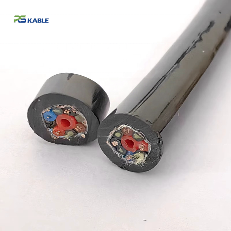
Can a simple parallel bundle — cable zip-tied to a hose — replace this product?
For single-cycle or low-frequency manual applications, a parallel bundle may be adequate. For drum applications cycling more than a few thousand times per year, it is not. A parallel bundle does not control differential bending stiffness between the cable and hose: the stiffer hose element induces uneven drum lay, causes the cable to seat eccentrically in the groove, and migrates out of the groove within 50,000–100,000 cycles under production load. The integrated RST-RH design controls this stiffness differential to within ±15%, maintaining a stable helical lay profile across the full rated cycle life.
What gases other than compressed air can the hose bore carry?
The PU bore is compatible with dry compressed air, nitrogen (N₂), argon, and argon/CO₂ welding gas mixtures at rated pressure. It is not suitable for oxygen-enriched air (fire risk with PU), acetylene, hydrogen, or any gas with a dewpoint above −20 °C at operating pressure (condensation degrades the bore surface over time). For CO₂ shielding gas in welding gantry applications: standard PU bore is confirmed compatible at pressures up to 16 bar and temperatures down to −30 °C. For any gas application outside this list, provide the gas composition and operating pressure to Rousheng before ordering.
Is the RST-RH cable available in ATEX-certified versions?
The standard RST-RH series is not ATEX-certified. An ETO variant with anti-static outer jacket (surface resistance < 10⁹ Ω per IEC 60093), ATEX-compatible insulation materials, and Zone 2 documentation (IIC gas group, T4 temperature class) is available. Minimum order for the ATEX ETO variant is 100 m. Provide the ATEX zone classification, gas group, and temperature class for your installation — Rousheng’s engineering team will confirm the material specification and applicable documentation.
What is the maximum continuous operating pressure and what happens if it is exceeded?
Maximum working pressures are 12 bar (6 mm bore), 16 bar (8 mm bore), and 20 bar (10 mm bore). Burst pressure is rated at ≥ 3× working pressure. Operating above working pressure does not cause immediate burst — the safety margin exists precisely to accommodate pressure spikes. However, sustained operation above working pressure causes accelerated creep in the PU bore wall, which progressively reduces wall thickness and burst margin over 200,000–400,000 cycles. The working pressure limit is a fatigue life boundary, not a structural limit. Size the hose bore such that system operating pressure is ≤ 80% of the rated working pressure to maintain adequate life margin.
Request a Quotation or Application Review
Rousheng provides specification confirmation and drum compatibility review at no charge before order placement. To receive a complete technical and commercial response — model selection, OD confirmation, lay pitch recommendation, rotary union interface notes — in a single reply, include the following:
- Equipment type and application (crane type, gantry, hoist, parking system, stage machinery)
- Maximum travel distance and required cable storage length
- Drum core diameter, flange diameter, and maximum number of storage layers
- Power core current draw and voltage; signal/data protocol (Ethernet tier, RS-485, control only)
- Hose bore ID (or required tool-end pressure + supply pressure for sizing assistance)
- Air fitting type and thread standard; connector type for electrical free end
- Operating temperature range and any chemical exposure
- Annual cycle estimate and required service life in years
- Replacement application: existing cable OD, fitting type and thread, rotary union port size
|
CONTACT |
Email: Jerry@rstlkable.com WhatsApp / Phone: +86 134 8219 7396 Address: No. 2591 Fengzhe Road, Fengxian District, Shanghai, China |