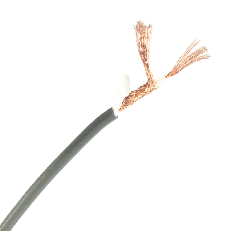
PUR Shielded Flexible Cable for Robotics Systems Low Noise Anti-Interference Supplier
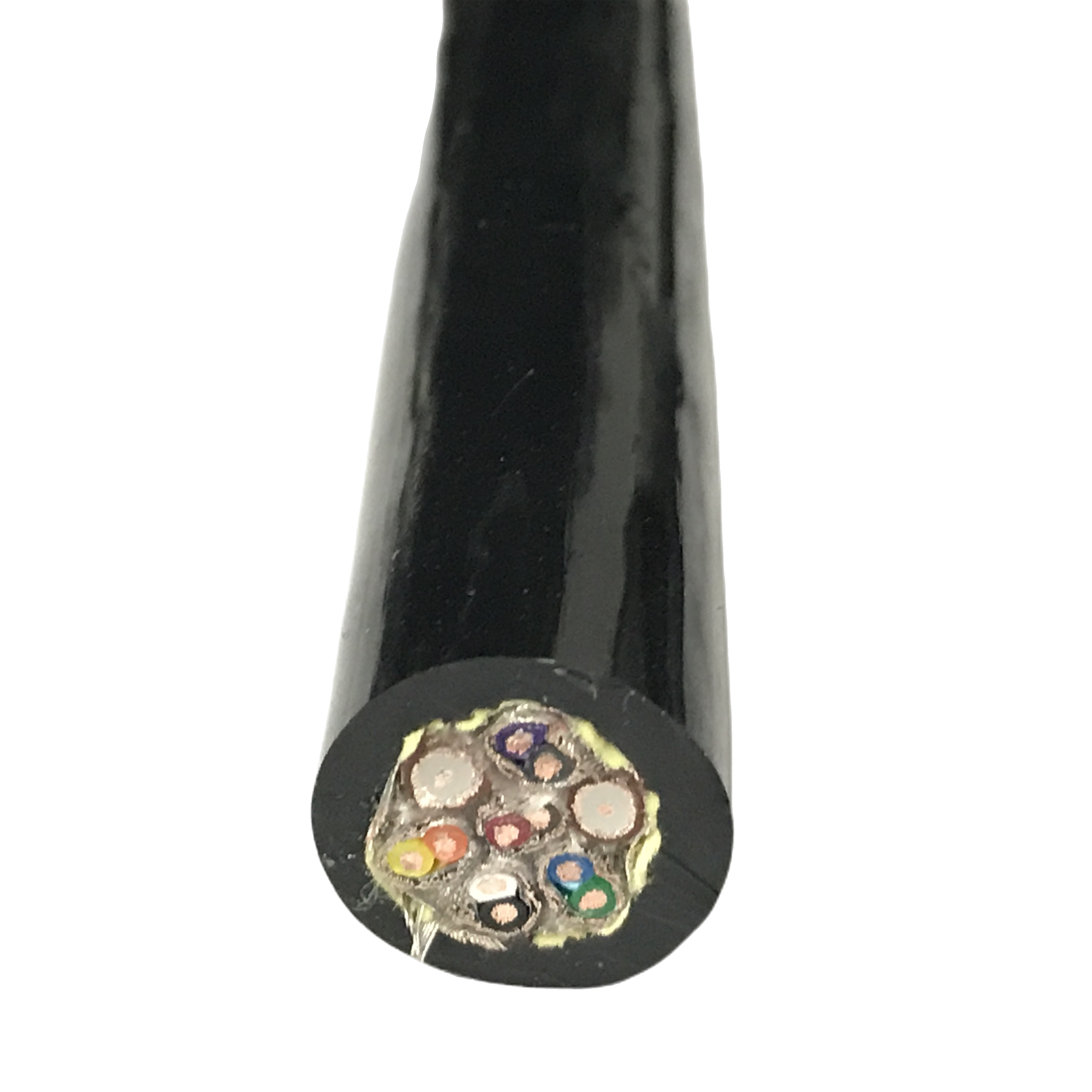
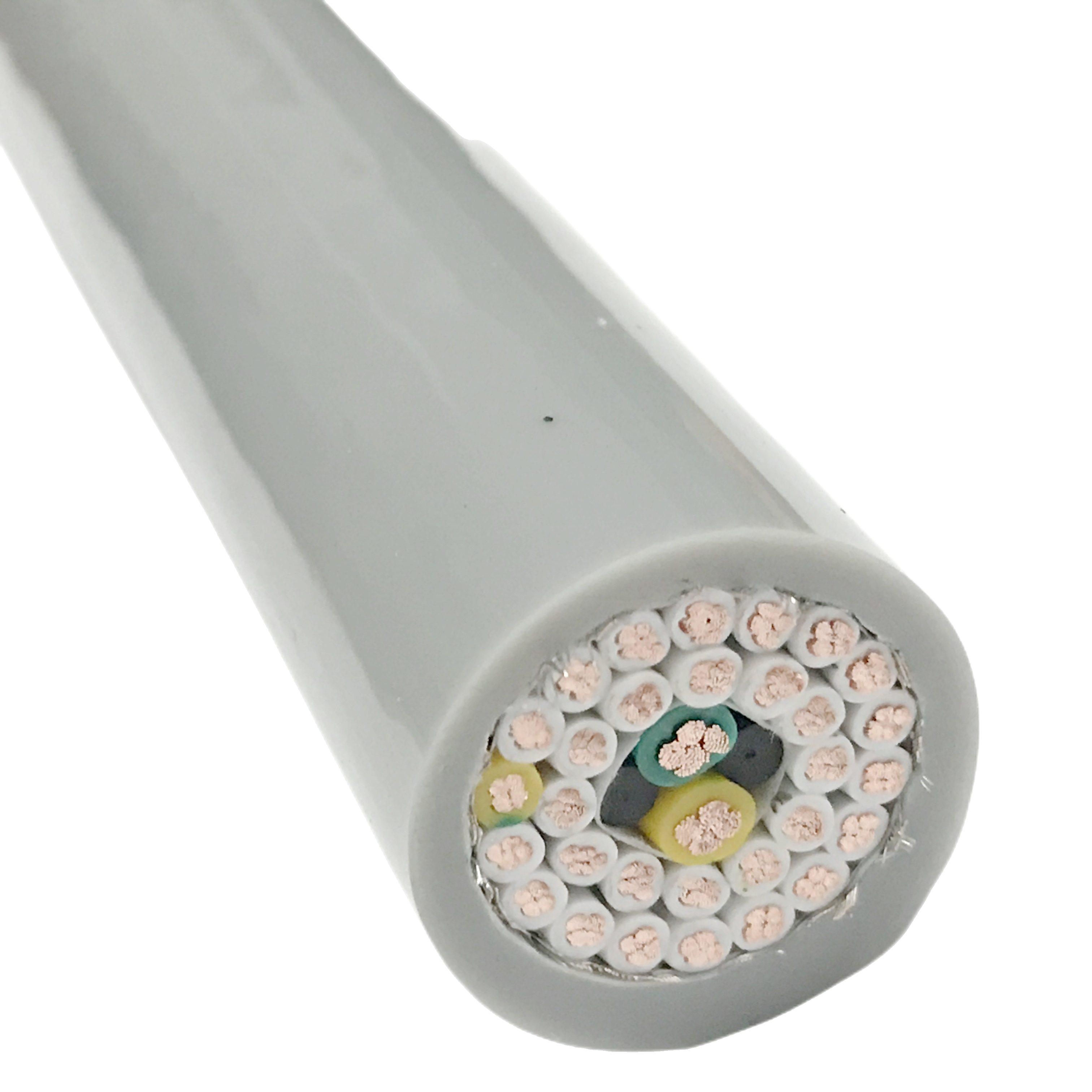
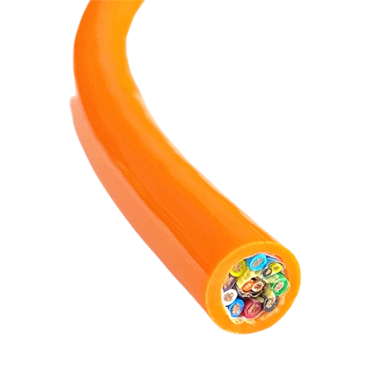
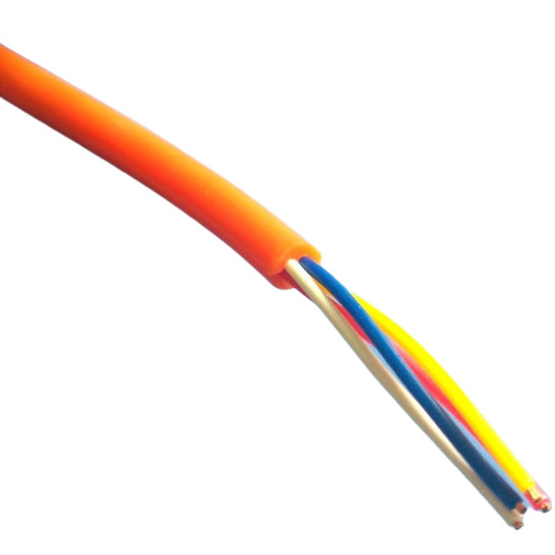
The RST-RS series is a PUR shielded flexible cable designed for robot wrist joints, encoder lines, and cobot tethers where simultaneous flex, torsion, and servo EMI degrade signal integrity. Transfer impedance < 25 mΩ/m maintained through 5,000,000 multi-axis cycles.
Key Benefits:
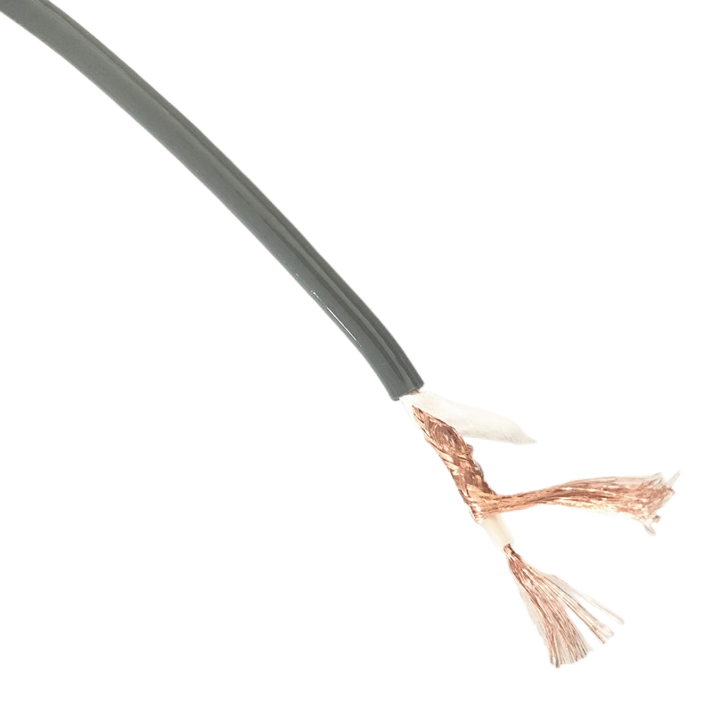
- Pair foil + tinned Cu braid — TI < 25 mΩ/m after 5M combined flex-torsion cycles
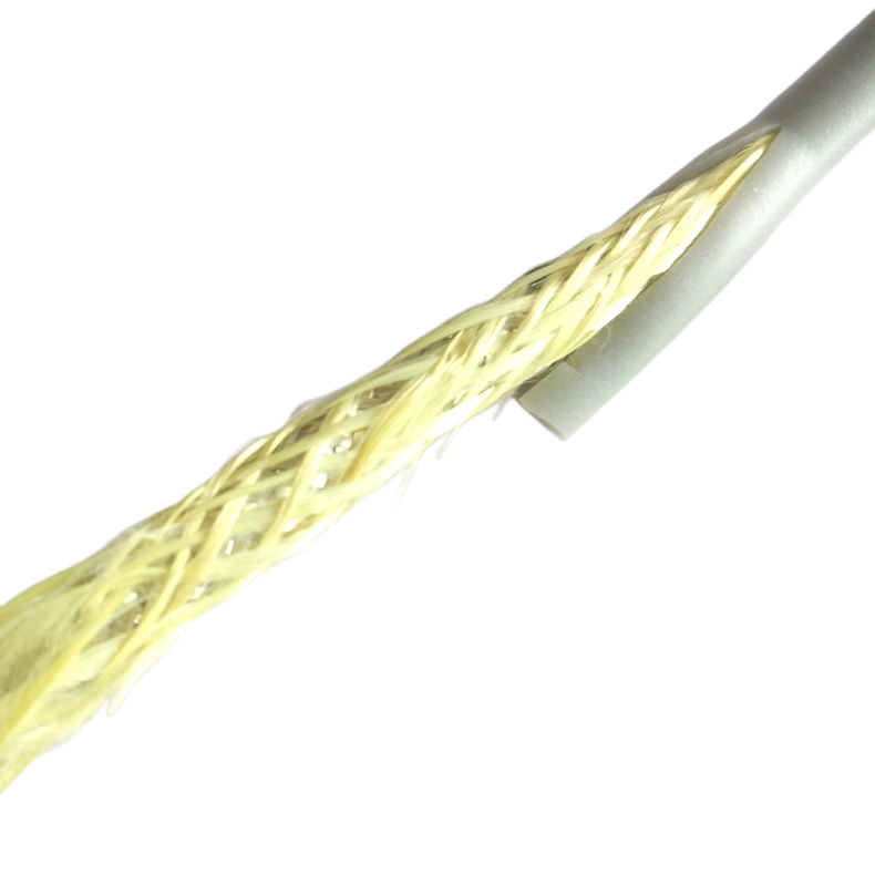
- 32–38° braid weave angle — validated for ±180°/m torsion with no coverage collapse
- Drain wire bonded at 60 mm — prevents torsion-driven drain separation at wrist joints
- Ether-type PUR 88 Shore A — no hydrolysis, oil resistant, −40 °C to +90 °C
- RST-RS-500 cobot variant — OD ±0.2 mm, ISO/TS 15066 mass certification
PUR Shielded Flexible Cable for Robotics Systems Low Noise Anti-Interference Supplier
A PUR shielded flexible cable for robot arms must maintain its electromagnetic shielding performance through a loading environment that static-installation shielded cables are never tested against: simultaneous bending at 5× OD radius, torsion at ±180° per metre, and axial extension — all three acting at the same time at every wrist joint motion cycle.
The Rousheng RST-RS series was developed after field analysis of a specific failure pattern: robot installations where encoder cables passed initial EMC qualification but produced position errors correlated with specific J4/J5 joint angles at 18–24 months of service. The failure traced to braid coverage collapse under multi-axis loading at the wrist bend point — a failure mode invisible to single-axis TDR testing and to TI measurements taken on straight cable sections.
This page documents the quantified shielding degradation mechanism, the construction parameters that prevent it, the full RST-RS product matrix, joint-specific signal protection requirements, bending stiffness physics behind the 5× OD minimum radius requirement, and field diagnostic methods for robot-specific EMI faults.
|
Transfer impedance |
Torsion + TI rating |
Drain bond pitch |
Min bend radius |
|
< 25 mΩ/m |
±180°/m — verified |
60 mm |
5× OD dynamic |
|
After 5M multi-axis cycles |
Shield integrity maintained |
Tighter than automation grade |
Shielded-cable specific |
Three Construction Decisions That Determine RST-RS Shielding Performance
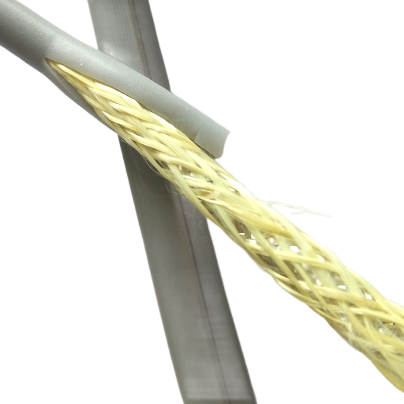
Decision 1 — Braid weave angle 32–38° for PUR shielded cable under robot torsion
Standard shielded cables for static installation use braid weave angles of 40–50° — optimised for maximum optical coverage at rest. When the cable is twisted, adjacent braid wires at these angles make contact and generate a stick-slip friction force that abrades the wire surface. Above ±90°/m torsion, the abrasion rate accelerates to the point where individual braid wires break within 300,000–500,000 cycles, creating permanent low-coverage zones at the locations of maximum torsion.
At angles below 28°, the complementary failure occurs: braid coverage collapses on the inside of the bend. The wires on the compression side of the bend cannot accommodate both the bend geometry and the coverage requirement simultaneously — they buckle, reducing optical coverage from the nominal 88% to 55–60% at 5× OD bend radius.
32–38° is the validated range that prevents both failure modes simultaneously under ±180°/m torsion combined with 5× OD bending. Coverage at 5,000,000 multi-axis cycles: ≥ 85%. Transfer impedance at 5M cycles: < 25 mΩ/m (pair foil + braid). This range was validated across 12 braid angle variants on Rousheng’s multi-axis test rig over an 18-month test programme.
Decision 2 — Drain wire bonded at 60 mm intervals (not 80 mm as in automation cables)
Under torsion, an unbonded drain wire lying parallel to the cable axis winds helically around the cable — the same way a loose wire wraps around a rotating shaft. Each ±180°/m torsion cycle winds the drain wire in one direction and then unwinds it in the reverse direction. The winding-and-unwinding motion abrades the drain wire against the foil surface at each contact point.
After 200,000–400,000 multi-axis cycles, the abrasion breaks the contact between the drain wire and the foil at the abraded points. The foil shield becomes electrically discontinuous at these points, creating a high-impedance zone that passes RF noise directly into the signal conductors. The fault is intermittent — the break closes under compression and opens under extension — producing the characteristic position-angle-correlated error pattern observed in the field.
RST-RS drain wires are bonded to the braid at 60 mm intervals using a conductive adhesive tape. This pitch was determined from torsion winding analysis: at ±180°/m torsion, the axial displacement of an unbonded wire section equals its pitch length × tan(lay angle) per half-cycle. A 60 mm bond pitch limits this displacement to < 3 mm per half-cycle — below the threshold that causes abrasion-driven impedance increase.
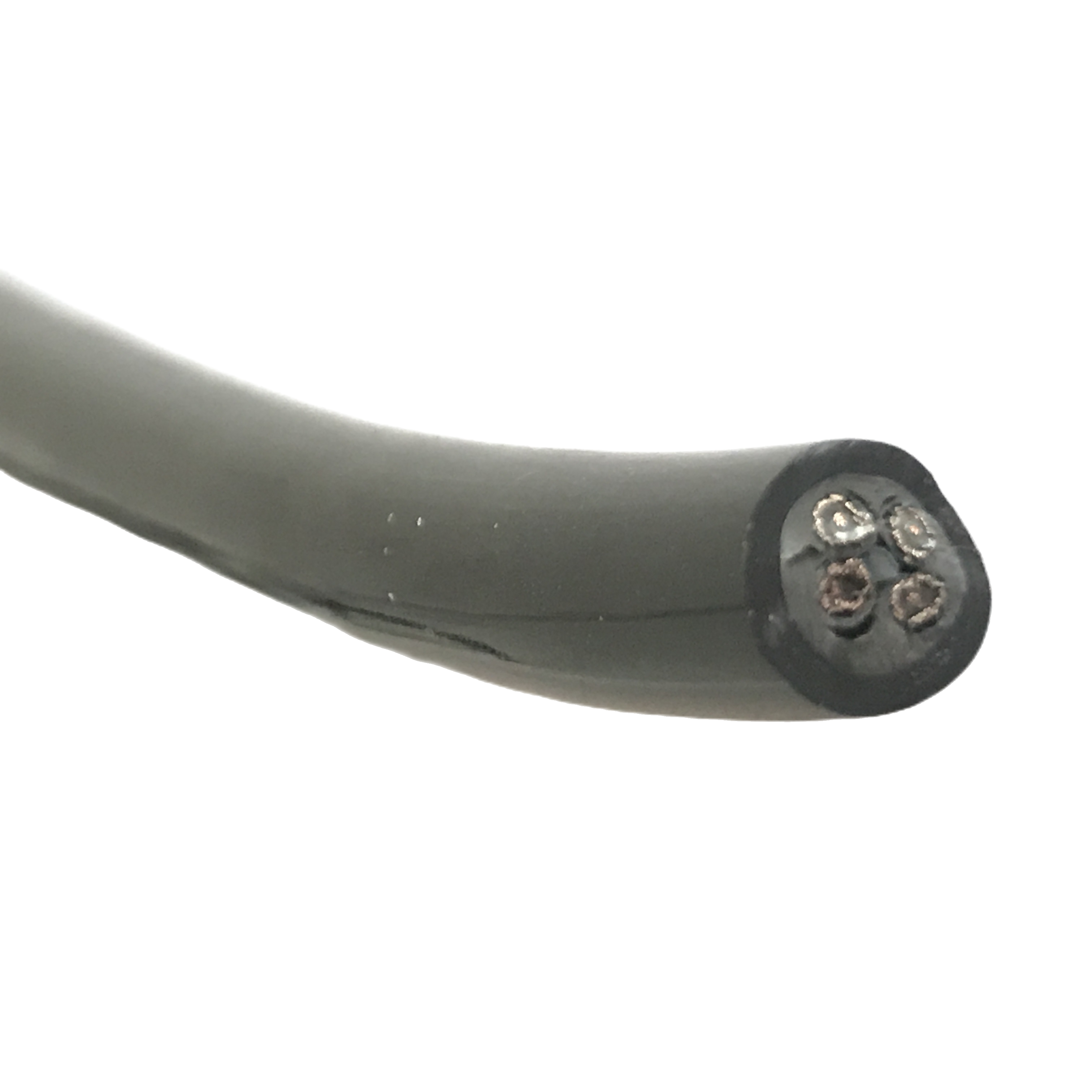
Decision 3 — 5× OD minimum bend radius: the bending stiffness physics
The question that every installer asks: why do RST-RS shielded models require 5× OD minimum bend radius when the equivalent unshielded RST-RB models need only 4× OD? The answer is quantitative.
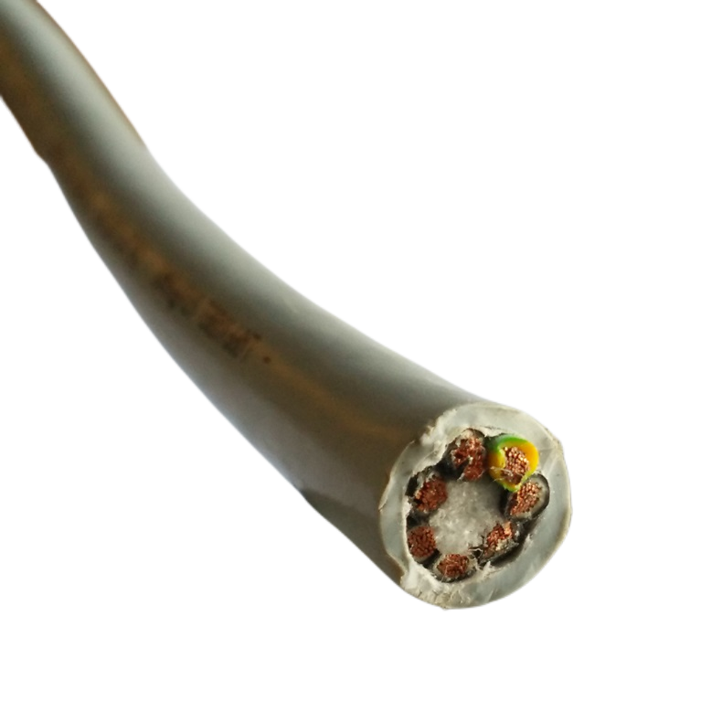
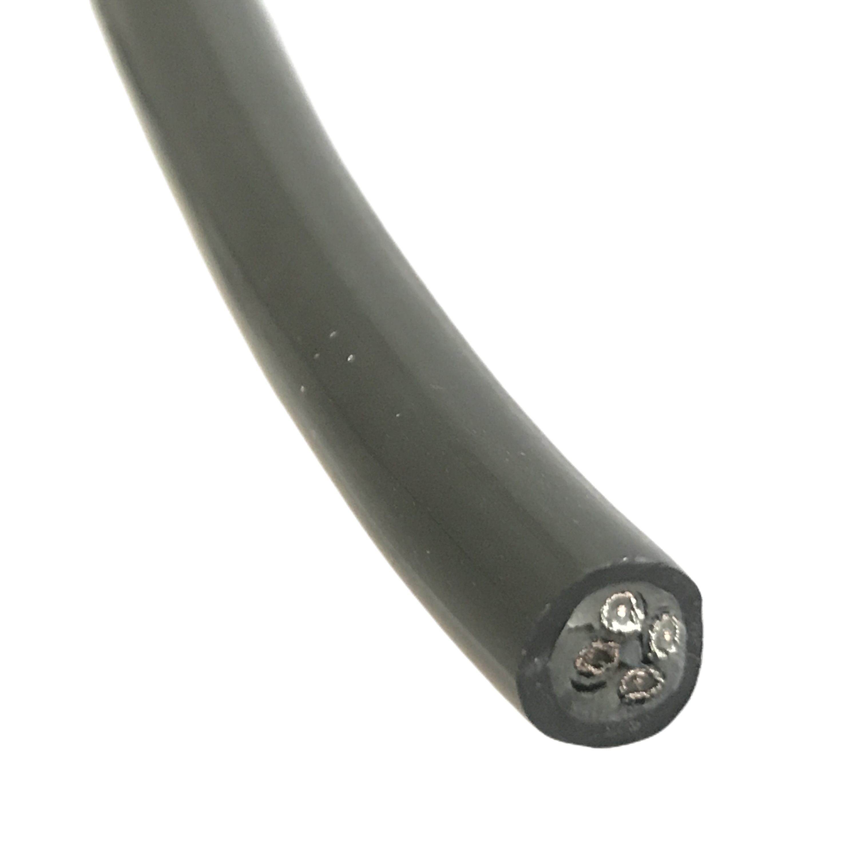
Bending stiffness (EI) of a cable cross-section depends on the material elastic moduli and the second moment of area of each element. The RST-RB unshielded core assembly has a calculated bending stiffness of approximately 1.0× (reference). Adding the AL/PET foil layer increases this to approximately 1.30× — a 30% stiffness increase from the foil alone. Adding the tinned copper braid at 88% coverage further increases stiffness to approximately 1.52× the unshielded reference.
To maintain the conductor bending stress below the copper fatigue endurance limit at 5,000,000 cycles, the minimum bend radius must scale with the square root of the stiffness ratio: √1.52 × 4× OD ≈ 4.93× OD — rounded to 5× OD in the specification. Using 4× OD on an RST-RS shielded cable does not cause immediate failure, but it raises conductor bending stress to approximately 118% of the endurance limit, reducing rated flex life from 5M cycles to approximately 2–2.5M cycles.
|
MEASURED SHIELDING DATA — MULTI-AXIS TEST |
RST-RS-220 (4 × 0.75 mm², pair AL/PET foil + overall Cu braid 88%) — IEC 62153-4-3 TI at simultaneous 5× OD flex + ±180°/m torsion: 0 cycles: 14 mΩ/m · 1M cycles: 16 mΩ/m · 3M cycles: 20 mΩ/m · 5M cycles: 24 mΩ/m Standard robot cable (no drain bonding, 45° braid, rigid PE filler): TI at 1M cycles: 95 mΩ/m; at 3M cycles: >200 mΩ/m (braid failure — unmeasurable). |
RST-RS Series Product Matrix
PUR shielded flexible cable for robotics — standard and cobot configurations
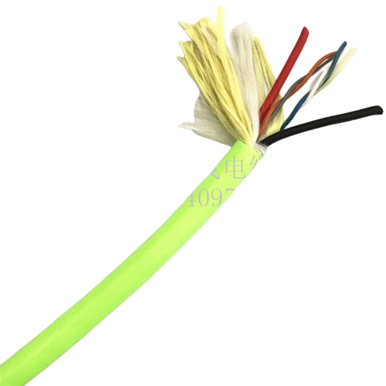
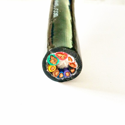
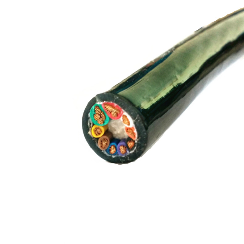
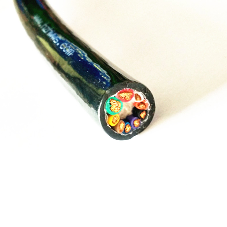
All RST-RS models: IEC 60228 Class 6 helical-lay OFC conductors, foamed TPE elastomeric filler, ether-type PUR 88 Shore A jacket, 32–38° braid weave angle. Flex life rated under simultaneous multi-axis loading.
|
Model |
Cores × mm² |
Shield |
Flex / torsion |
TI @ 1 MHz |
OD (mm) |
Min bend R |
Primary use |
|
RST-RS-110 |
4 × 0.34 mm² |
Cu braid |
5M / ±180°/m |
< 32 mΩ/m |
6.5±0.3 |
5× OD = 33 mm |
J1–J3 signal |
|
RST-RS-120 |
4 × 0.75 mm² |
Cu braid |
5M / ±180°/m |
< 32 mΩ/m |
8.2±0.3 |
5× OD = 41 mm |
J1–J3 control |
|
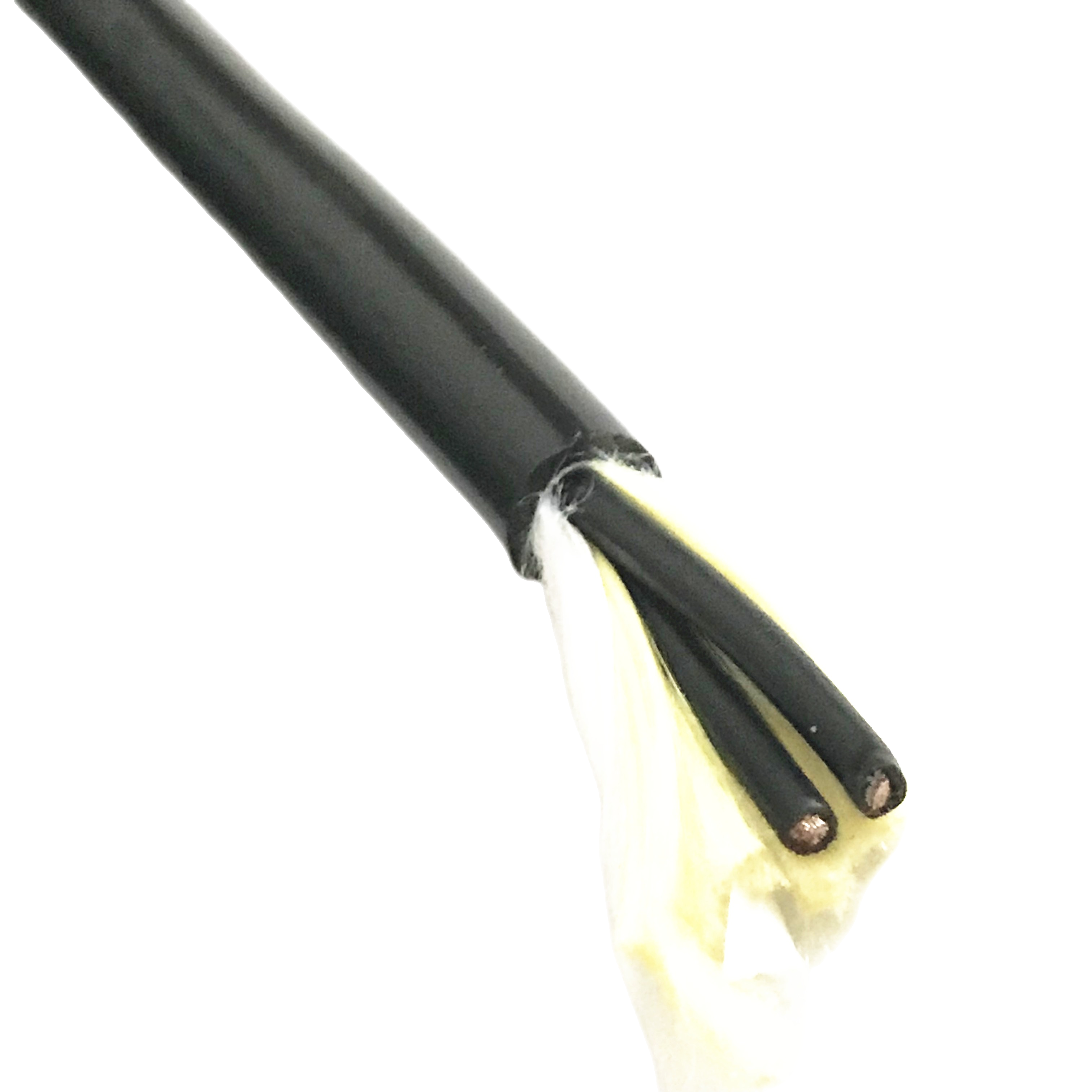
RST-RS-130 |
7 × 0.75 mm² |
Cu braid |
5M / ±180°/m |
< 32 mΩ/m |
10.5±0.4 |
5× OD = 53 mm |
Lower arm I/O |
|
RST-RS-210 |
4 × 0.34 mm² |
Foil/pr + braid |
5M / ±180°/m |
< 25 mΩ/m |
7.8±0.3 |
5× OD = 39 mm |
J4/J5 signal |
|
RST-RS-220 |
4 × 0.75 mm² |
Foil/pr + braid |
5M / ±180°/m |
< 25 mΩ/m |
9.5±0.3 |
5× OD = 48 mm |
J4/J5 control |
|
RST-RS-230 |
12 × 0.75 mm² |
Foil/pr + braid |
5M / ±180°/m |
< 25 mΩ/m |
14.0±0.4 |
5× OD = 70 mm |
J4/J5 full I/O |
|
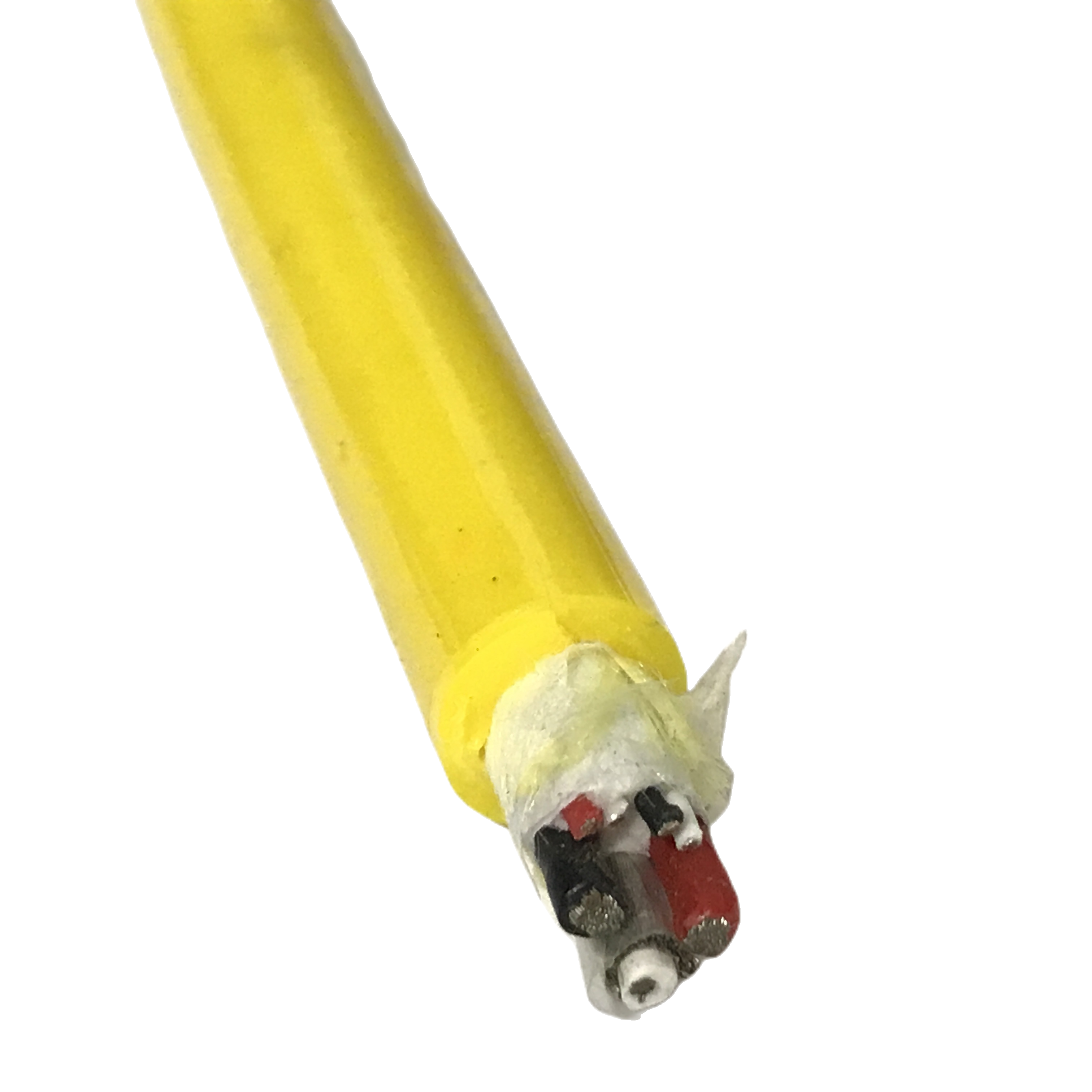
RST-RS-310 |
2 pr × 0.14 mm² |
Foil/pr + braid |
5M / ±180°/m |
< 18 mΩ/m |
6.8±0.3 |
5× OD = 34 mm |
J6 encoder |
|
RST-RS-320 |
4 pr × 0.25 mm² |
Foil/pr + braid |
5M / ±180°/m |
< 18 mΩ/m |
9.2±0.3 |
5× OD = 46 mm |
Multi-encoder/SSI |
|
RST-RS-410 |
3×1.5 + 4×0.75 |
Signal foil+braid |
3M / ±90°/m |
< 30 mΩ/m |
15.0±0.5 |
5× OD = 75 mm |
Servo pwr + ctrl |
|
RST-RS-500 (cobot) |
4 × 0.75 mm² |
Foil/pr + braid |
5M / ±180°/m |
< 25 mΩ/m |
9.5±0.2 |
5× OD = 48 mm |
ISO/TS 15066 cobot |
|
RST-RS-C (ETO) |
Per spec |
Per spec |
Per design |
Per design |
4–25 mm |
Per design |
PUR/LSZH/TPE |
Min bend radius column: Values are calculated as 5× cable OD (dynamic). Conduit internal radius at each robot joint must be ≥ this value. RST-RS shielded models require 5× OD vs 4× OD for unshielded RST-RB models — see Section 4 for the bending stiffness calculation that determines this requirement.
Complete Technical Specification
Conductors, shielding, and filler for robot PUR shielded cable
|
Parameter |
Specification |
|
Conductor standard |
IEC 60228 Class 6 helical lay; wire count: 0.14 mm²: ≥100 · 0.25 mm²: ≥115 · 0.34 mm²: ≥130 · 0.75 mm²: ≥196 · 1.5 mm²: ≥280 |
|
Lay type |
Helical lay 15–20° per OD; layer reversal between concentric layers. Required for ±180°/m torsion rating — straight-stranded lay generates torsional bending stress not present in helical lay |
|
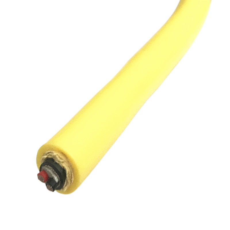
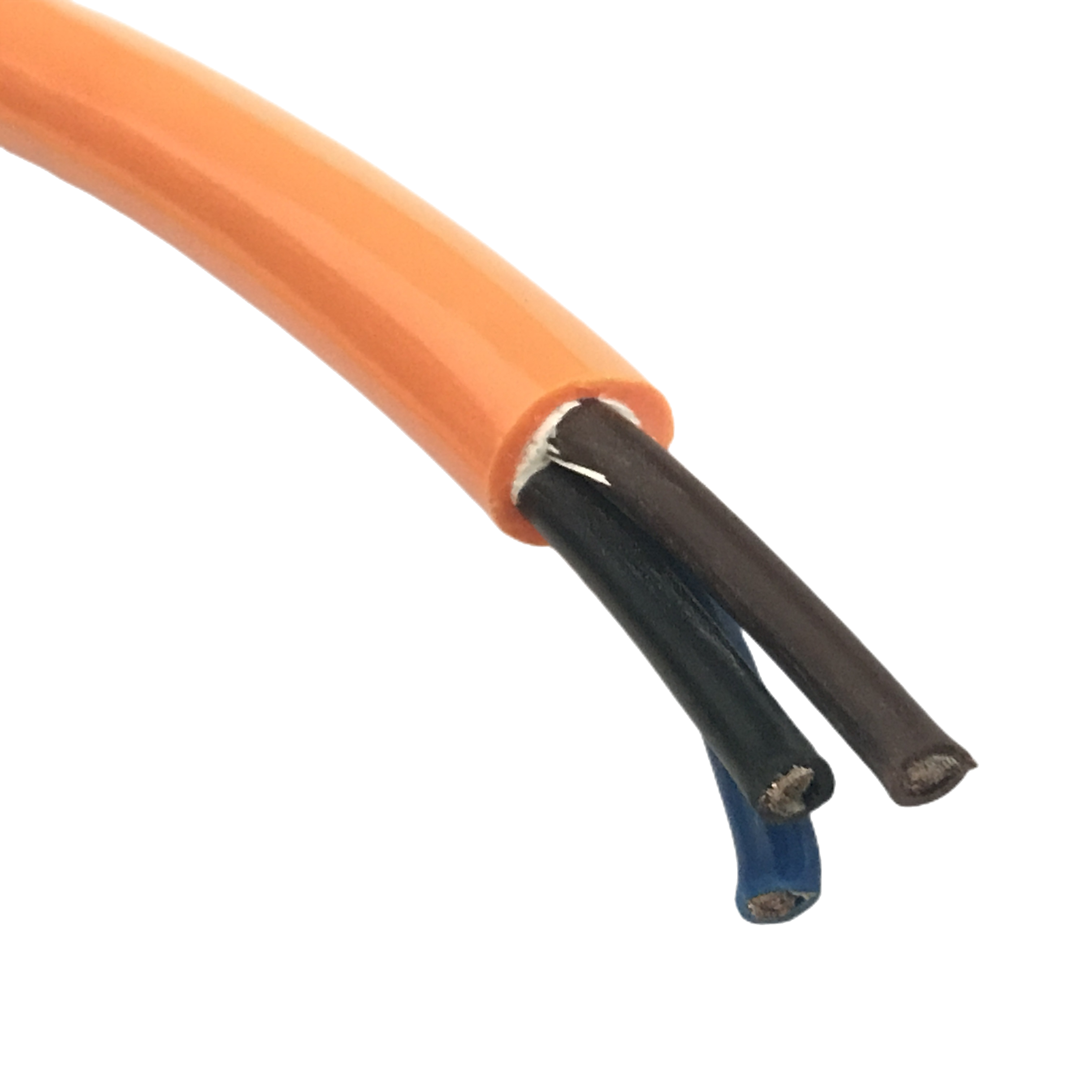
Pair shield (2xx/3xx/4xx/500 models) |
AL/PET foil, 100% coverage; drain wire 0.5 mm² OFC bonded at 60 mm intervals. 60 mm pitch prevents torsion-driven drain winding under ±180°/m (at this pitch, axial displacement per half-cycle < 3 mm — below the abrasion threshold) |
|
Overall braid — all models |
Tinned Cu braid; optical coverage ≥ 88% initial; ≥ 85% at 5M multi-axis cycles; weave angle 32–38° validated for simultaneous 5× OD bending + ±180°/m torsion |
|
Transfer impedance — overall braid |
< 32 mΩ/m initial; < 35 mΩ/m after 5M multi-axis cycles. Measured per IEC 62153-4-3 at simultaneous flex + torsion — not static TI on straight cable section |
|
Transfer impedance — pair foil + braid |
RST-RS-2xx/4xx/500: < 25 mΩ/m initial; < 28 mΩ/m after 5M cycles. RST-RS-3xx encoder: < 18 mΩ/m initial; < 22 mΩ/m after 5M cycles |
|
Core filler |
Foamed TPE, 45–55 Shore A; cross-section ovality ≤ 3.2% after 5M multi-axis cycles (vs unshielded RST-RB ≤ 2.8% — 0.4% difference due to braid stiffening limiting TPE recovery) |
|
Serve layer |
Polyester textile serve between core and pair shield/jacket; allows ±5° core rotation relative to jacket under torsion — prevents jacket from transmitting torsion to conductors |
|
Outer jacket |
Ether-type PUR 88 Shore A; −40°C to +90°C; Group 1 oil resistance ≥ 80% tensile retention (IEC 60811-2-1, 7-day immersion at 70°C); Taber abrasion 18 mg / 1,000 cycles (CS-10, 500 g) |
|
Voltage rating |
Signal/control cores: 300/500 V AC. Power cores (RST-RS-410): 450/750 V AC. Withstand test: 2,000 V AC / 1 min per production lot |
Bend radius stiffness calculation — PUR shielded flexible cable vs unshielded
The 5× OD vs 4× OD minimum bend radius difference between shielded and unshielded models is derived from bending stiffness analysis, not from an arbitrary safety margin. The table below shows the stiffness contribution of each layer and the resulting minimum bend radius.
|
Cable configuration |
Bending stiffness (EI) relative |
Min bend radius factor |
At 5M cycles: conductor stress |
|
RST-RB unshielded (reference) |
1.00× (reference) |
4× OD |
At endurance limit — 5M cycles achieved |
|
+ AL/PET foil layer |
1.30× (+30% from foil) |
4.5× OD minimum |
Borderline — reduced life margin |
|
+ AL/PET foil + Cu braid (RST-RS) |
1.52× (+52% from foil + braid) |
5× OD (√1.52 × 4 = 4.93, rounded up) |
At endurance limit — 5M cycles achieved |
|
RST-RS at 4× OD (under-specified) |
1.52× (same as above) |
4× OD — below minimum |
~118% of endurance limit — flex life reduces to ~2–2.5M cycles |
Signal Protection and Free Length by Robot Joint
PUR shielded robot cable selection: joint requirements and service loop geometry
Each robot joint requires a different combination of shielding level, torsion-rated free length, and minimum conduit radius. The table below gives all three parameters together — reducing the number of separate lookups required during robot arm cable design.
|
Axis |
Model |
Free length (min) |
Conduit radius ≥ |
Notes |
|
J1 base rotation (±200°/−160°, asymmetric) |
RST-RS-120 |
360° ÷ 180 × 1.20 = 2.40 m |
5× 8.2 mm = 41 mm |
Asymmetric axis: total angle = 200 + 160 = 360°, not 2 × 200 = 400°. Overall braid adequate at J1 distance from servo motor. |
|
J2/J3 lower arm |
RST-RS-130 |
≈ 1.4–1.8 m (joint-dependent) |
5× 10.5 mm = 53 mm |
Lower arm flex is near-planar; torsion typically < ±30°/m. 7-core model covers full lower arm I/O in one cable. |
|
J4/J5 wrist |
RST-RS-220 (mandatory dual shield) |
360° ÷ 180 × 1.20 = 2.40 m |
5× 9.5 mm = 48 mm |
Dual shield mandatory — J4/J5 servo switching harmonics reach 100 kHz; pair foil required for encoder isolation. Verify conduit radius ≥ 48 mm before routing. |
|
J6 tool rotation (±360°) |
RST-RS-310 |
720° ÷ 180 × 1.20 = 4.80 m |
5× 6.8 mm = 34 mm |
See service loop geometry note below. |
|
Cobot — all axes (PFL mode) |
RST-RS-500 |
Per axis rotation |
5× 9.5 mm = 48 mm |
OD ±0.2 mm for collision model. Cobot SSM mode: RST-RS-220 acceptable. PFL mode: RST-RS-500 mandatory — OD variation causes ±8% collision force calculation error. |
J6 encoder cable: service loop geometry for 4.80 m free length
A 4.80 m free cable length at J6 cannot be routed as a straight run — there is no straight 4.80 m path between the J5/J6 junction and the end effector on any standard 6-axis robot. The correct installation forms the free cable into a service loop in the J5/J6 housing area.
The loop must have an internal radius ≥ 34 mm (5× OD of RST-RS-310 at 6.8 mm OD). A 4.80 m free length coiled into a loop of 34 mm internal radius requires approximately 4 full loop turns in a 68 mm diameter coil — geometrically feasible in most J5/J6 housing cavities. As J6 rotates ±360°, the cable rotates within the loop; the loop does not translate. The torsion is absorbed across the full 4.80 m free length, keeping the per-metre torsion load below the ±180°/m rating.
If the J5/J6 housing does not have cavity space for 4 loop turns: specify RST-RS-C ETO at ±270°/m torsion rating. At ±270°/m, the minimum free length for ±360° J6 rotation reduces from 4.80 m to 3.20 m — saving 1.60 m of cable and approximately 2 loop turns.
|
J6 FREE LENGTH SUMMARY |
Standard RST-RS-310 at ±180°/m: J6 ±360° requires 4.80 m free length → 4 loop turns at 34 mm internal radius. ETO RST-RS-C at ±270°/m: J6 ±360° requires 3.20 m free length → 3 loop turns at 34 mm internal radius — specify if J5/J6 housing is space-constrained. In both cases, the loop rotates in place as J6 turns. Mount the fixed end of the loop at the J5/J6 structure, not at the J6 output flange. |
Shield Grounding in Robot Installations
Why robot cable shield grounding differs from static installation practice
In a static panel installation, shield grounding is a fixed circuit: ground the shield at the controller end, float at the sensor end, and the shield current path is constant. In a robot arm, the shield grounding path changes with every joint angle because the electrical impedance of the robot structure between the end effector ground and the cabinet earth varies as joint positions change.
This variation creates a rotating ground impedance — the shield current that flows through the robot structure to reach cabinet earth changes in magnitude and phase with each joint movement. If the shield is grounded at both ends (cable shield to controller cabinet AND end effector chassis to tool changer ground), this rotating impedance generates a current in the shield that modulates with joint angle — exactly the pattern seen in angle-correlated signal noise.
Recommended grounding scheme for RST-RS robot cables
- Ground the shield at the servo drive / controller cabinet end only. The termination point must be bonded to the cabinet protective earth rail, not to the signal reference ground.
- Float the shield at the end effector end. The connector backshell at the tool changer should be insulated from the tool changer housing by a non-conductive grommet or an isolated connector shell.
- For cobot RST-RS-500 applications: additionally verify that the force-torque sensor chassis is not connected to the shield drain — the sensor’s electrical ground and the cable shield drain must be independent paths back to the controller cabinet. A common ground at the sensor side converts shield current into force sensor input noise.
Measuring shield grounding correctness in an installed robot
With the robot at the J4/J5 fault angle (if a fault angle was identified during troubleshooting): clamp a current meter around the outer braid of the cable at the J4/J5 joint. Measure shield current with servo drives enabled at rated motor speed.
Shield current > 30 mA with drives enabled and < 5 mA with drives disabled: confirming correct single-end grounding with drive switching as the current source — normal. Shield current > 30 mA with drives disabled: ground loop current path exists through the robot structure — the shield is grounded at both ends via the robot chassis. Float the shield at the end effector end.
|
GROUNDING RULE |
Single-end ground — shield at drive cabinet end only. Applies to: all encoder cables (RST-RS-310/320), all analogue feedback cables, all RST-RS signal cables at J4/J5 and J6. Both-ends ground — only for safety circuit cables (E-stop, safety relay) where the cable is not sensitive to 50 Hz induction and the both-ends path provides a defined PE path. |
Cobot-Specific Requirements: RST-RS-500
When standard PUR shielded cable is not adequate for collaborative robots
ISO/TS 15066 power-and-force-limiting (PFL) mode uses the mass and outer geometry of every cable in the robot’s collaborative workspace as inputs to the collision force model. A cable whose outer diameter varies by ±0.5 mm (standard RST-RS tolerance) introduces a mass uncertainty of ±2.5% into the collision calculation — tolerable for many applications, but above the ±2% tolerance required for certified PFL compliance in close-proximity human-robot work.
The ±8% figure cited frequently in cobot safety discussions comes from combining OD tolerance uncertainty (±2.5%) with cable routing geometry uncertainty (±3%) and joint velocity uncertainty (±2.5%). RST-RS-500 eliminates the OD tolerance contribution by tightening to ±0.2 mm, reducing total collision force uncertainty to approximately ±5.5% — within the ISO/TS 15066 Annex A acceptable range for most body contact locations.
RST-RS-500 specific parameters
|
Parameter |
RST-RS-500 value |
|
OD tolerance |
±0.2 mm (standard RST-RS: ±0.3–0.5 mm). Certified per batch on dimensional inspection report included with each shipment |
|
Outer surface geometry |
Seam-free circumferential profile; no extruder ridge or surface projection. Irregular surface geometry concentrates contact force at projections — registered by force sensors as a larger contact area than the cable cross-section, overestimating collision force |
|
Mass per metre |
100 ± 3 g/m (4 × 0.75 mm², shielded). Certified on delivery note for ISO/TS 15066 payload calculation. Different core counts change mass — confirm at order |
|
Collision force error reduction |
OD ±0.2 mm reduces OD contribution to force uncertainty from ±2.5% to ±0.8%. Total force calculation uncertainty (combined OD + routing + velocity): ~±5.5% vs ~±8% for standard tolerance cables |
|
Safety mode applicability |
PFL mode: RST-RS-500 mandatory. SSM (speed-and-separation monitoring) mode: standard RST-RS-220 acceptable — cable is not in contact with operator, mass and OD are not direct safety inputs in SSM |
|
Technical file documentation |
OD certification, mass certificate, TI test report, and dimensional inspection report — provided per production lot for inclusion in cobot system CE technical file under Machinery Directive 2006/42/EC Annex VII |
Field Diagnostic Reference: Robot Shielded Cable EMI Failures
Identifying PUR shielded flexible cable failures by symptom and measurement
The following five failure patterns are drawn from Rousheng’s robot cable field service records. Each includes the specific test that confirms the root cause — not just the symptom description.
|
Symptom |
Root cause |
Confirming test |
Pass/fail threshold |
Correction |
|
Position error at specific J4/J5 angle — same error at same angle, repeatable |
Braid coverage collapse at wrist bend — low-coverage zone coincides with servo switching peak at that joint angle |
TI measurement at 1 MHz per IEC 62153-4-3 with cable held at the fault angle vs neutral angle |
TI > 60 mΩ/m at fault angle vs < 35 mΩ/m at neutral = braid failure at wrist |
Replace with RST-RS-220 (32–38° braid, TI < 25 mΩ/m after 5M cycles). Verify conduit internal radius ≥ 48 mm (5× 9.5 mm OD). Confirm drain bonding by measuring drain-to-braid resistance at fault angle: should be < 0.5 Ω. |
|
Encoder noise proportional to motor current — not to motor speed |
Magnetic field coupling from motor power cable — not shielding failure |
Move motor power cable 150 mm away from encoder cable. If noise drops > 15 dB: magnetic coupling confirmed |
Noise drop > 15 dB when separated = coupling (not shielding fault) |
Re-route motor cable; minimum 150 mm separation or grounded metal divider. If space constraint: RST-RS-310 (TI < 18 mΩ/m) provides additional 14 dB margin. Verify single-end shield grounding — double-grounded shield carries induced current that amplifies magnetic coupling. |
|
Shield continuity alarm at J6 — varies with joint rotation angle |
Drain wire wound around cable axis under torsion — drain-to-braid contact intermittent |
Drain-to-braid resistance measured at J6 = 0°, 90°, 180°, 270° |
Drain-to-braid resistance > 5 Ω at any rotation angle = drain separation |
Replace with RST-RS-310 (drain bonded at 60 mm intervals). After replacement, confirm drain-to-braid resistance < 0.5 Ω at all J6 rotation angles. Verify free length ≥ 4.80 m and service loop geometry correct (4 turns, 34 mm internal radius, fixed to J5/J6 structure). |
|
Angle-correlated noise on 4–20 mA analogue signal — increases as J4/J5 approaches specific angle |
Shield grounded at both ends via robot structure — rotating ground impedance generates joint-angle-modulated shield current |
Disconnect shield at end effector end temporarily. If signal improves at fault angle: ground loop through robot structure confirmed |
Signal improvement > 10 dB with shield floated at end = ground loop via robot chassis |
Float shield at end effector end using insulated connector backshell or non-conductive grommet at tool changer. Measure shield current at fault angle after change — should drop below 5 mA with drives disabled. If above 5 mA with drives disabled: additional ground path exists through the robot structure. |
|
Cobot safety stop triggered by cable — false alarm at specific arm configuration |
Electrical noise on force-torque sensor cable interpreted as contact force — TI too high OR force sensor shield grounded at tool end |
Enable servo drives; measure noise on force sensor signal with oscilloscope. Compare noise at fault arm configuration vs drives-disabled |
Noise > 50 mV peak-to-peak on 0–100 N force sensor signal = EMI coupling |
1) If noise > 50 mV: replace with RST-RS-500 (TI < 25 mΩ/m). 2) Float force sensor cable shield at sensor end — grounding at sensor creates the variable-impedance ground loop. 3) Verify RST-RS-500 OD ±0.2 mm certification for PFL mode collision model. 4) Confirm cobot safety mode is PFL — if SSM, standard RST-RS-220 is sufficient. |
Frequently Asked Questions
Why does a PUR shielded flexible cable for robots need a tighter drain wire bond than an automation panel cable?
In a static panel installation, the drain wire lies parallel to the cable axis without being subjected to torsion — it stays in contact with the foil without needing mechanical bonding. At a robot wrist joint under ±180°/m torsion, an unbonded drain wire winds helically around the cable axis like a thread on a screw. The winding-and-unwinding cycle abrades the drain-to-foil contact point, breaking electrical continuity at 200,000–400,000 cycles. RST-RS uses 60 mm bonding pitch (vs 80 mm for automation cables) to limit drain displacement below the abrasion threshold.
Can I use the same cable for J1 and J4/J5 joints?
Not optimally. J1 is far from the servo motor, in a low-EMI location — overall braid (RST-RS-120) provides adequate shielding. J4/J5 is adjacent to the servo motor; servo switching harmonics at 50–100 kHz require pair-level foil isolation that overall braid alone cannot provide. Using RST-RS-220 (pair foil + braid) everywhere works — it is never under-specified — but adds OD and cost at J1 where overall braid is sufficient. Specify by joint location for optimal cable selection.
How do I calculate the minimum conduit radius for an RST-RS shielded cable?
Multiply the cable OD by 5. This is the minimum dynamic bend radius for all RST-RS shielded models. Example: RST-RS-220 (OD 9.5 mm) — minimum conduit internal radius = 5 × 9.5 = 47.5 mm. This is 25% larger than the equivalent unshielded RST-RB-220 (OD 8.8 mm, 4× OD = 35 mm). The difference comes from the bending stiffness added by the AL/PET foil and Cu braid layers — a combined stiffness increase of approximately 52% over the unshielded core assembly.
Is RST-RS-500 required for all cobot applications?
Only for PFL (power-and-force-limiting) mode where the cable is in the collaborative workspace and its mass and OD are inputs to the collision force model. In SSM (speed-and-separation monitoring) mode, the cobot stops before contact — cable OD and mass are not direct safety inputs. RST-RS-220 is acceptable in SSM mode. Confirm the cobot safety mode with the system integrator before specifying. Incorrect specification in PFL mode introduces up to ±8% combined collision force uncertainty — above the ISO/TS 15066 Annex A acceptable threshold for most body contact locations.
What is the minimum order quantity for RST-RS standard and cobot models?
Standard RST-RS models (RST-RS-110 through RST-RS-410) and RST-RS-500 cobot model: minimum 50 m on reel or 10 assembled units with IP67 connectors. RST-RS-C ETO designs: minimum 100 m from first production run with first-article inspection before production release. Samples of 1–5 m are available for application engineering evaluation. RST-RS-500 cobot model includes OD certification report, mass-per-metre certificate, and TI test report with every shipment at no additional charge.
Request Samples, TI Test Data, or a Quotation
Getting the right shielded robot cable specified for your application
Rousheng provides a free application review — joint-specific model recommendation, conduit radius check, J6 service loop geometry calculation, and cobot safety mode assessment — before order placement. Transfer impedance test reports under multi-axis loading conditions are available on request.
For a complete single-reply response, include:
- Robot make and model, or axis-by-axis range of motion (positive and negative degrees, asymmetric axes noted separately)
- Joints requiring shielded cable: J1–J6 identifications — affects model (overall braid vs pair foil + braid)
- Signal type at each joint: encoder, resolver, analogue 4–20 mA, digital I/O, or combined
- Conduit internal radius at J4/J5 and J6 — required to verify 5× OD minimum bend radius is achievable
- J6 housing cavity dimensions if J6 service loop is required — confirms loop geometry feasibility
- Cobot application: yes/no; if yes, safety mode (PFL or SSM) and ISO/TS 15066 compliance requirement
- Interference source: servo drive make and switching frequency if known; VFD type if co-routed
- Oil or chemical environment: fluid type and contact mode (splash vs immersion)
- Required service life and annual cycle rate
- Quantity: metres on reel, or assembled units with connector type at each end
|
CONTACT |
Email: Jerry@rstlkable.com WhatsApp / Phone: +86 134 8219 7396 Address: No. 2591 Fengzhe Road, Fengxian District, Shanghai, China Sample requests: state RST-RS model, OD, joint (J1–J6 or cobot), and signal type. |