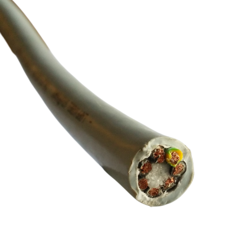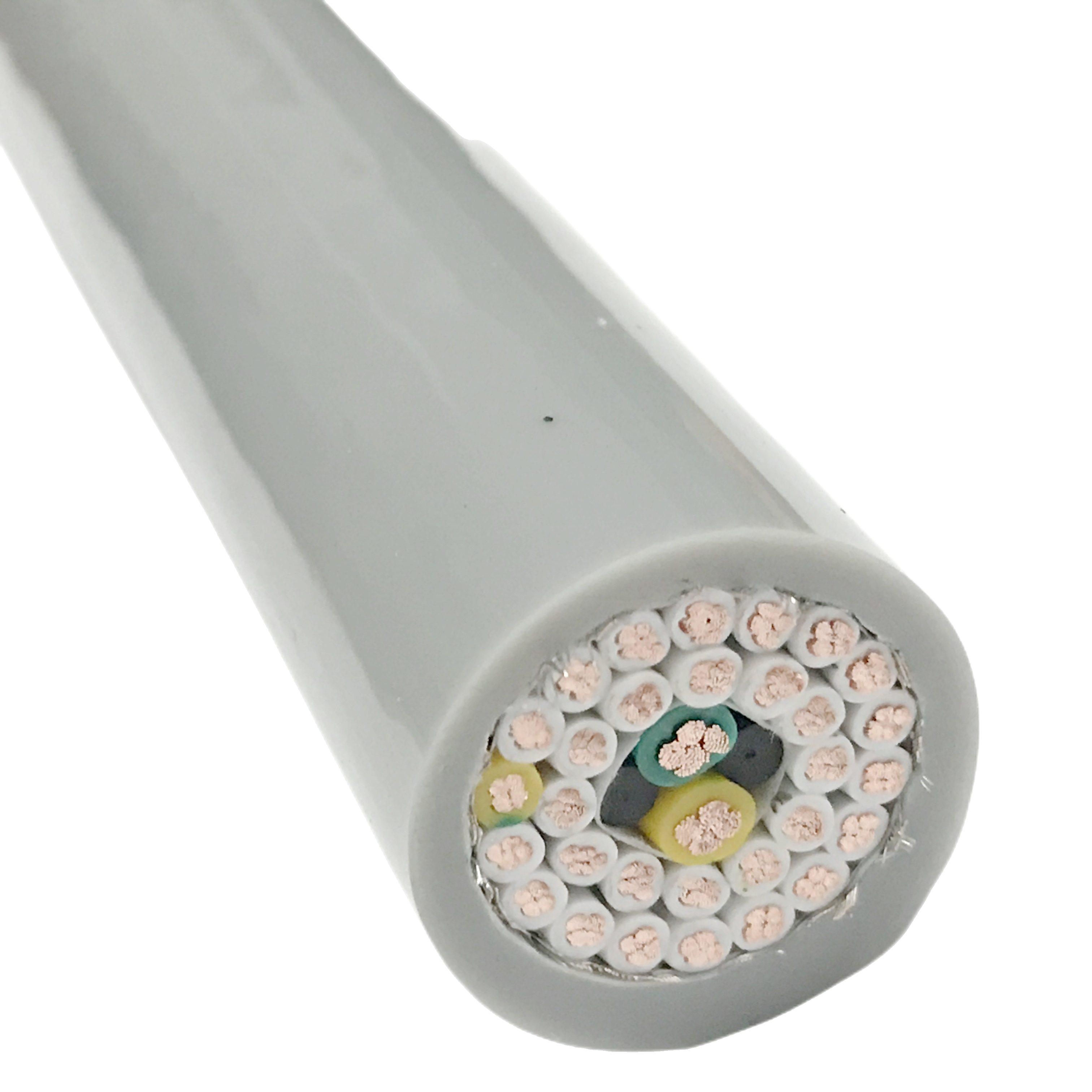
PUR Shielded Flexible Cable for Industrial Automation EMI Protection High Flex Cable Manufacturer
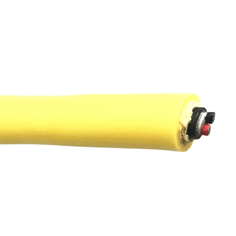
The RST-SH series is a PUR shielded flexible cable engineered for automation environments where VFD, servo, and switching noise degrades signal integrity. Transfer impedance < 30 mΩ/m maintained through 5,000,000 flex cycles.
Key Benefits:
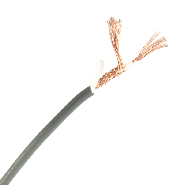
✅ Tinned Cu braid ≥ 90% coverage — TI < 30 mΩ/m at 1 MHz through 5M cycles
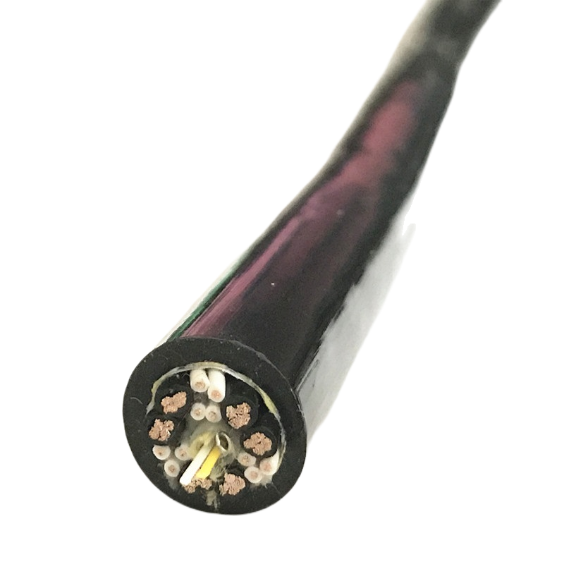
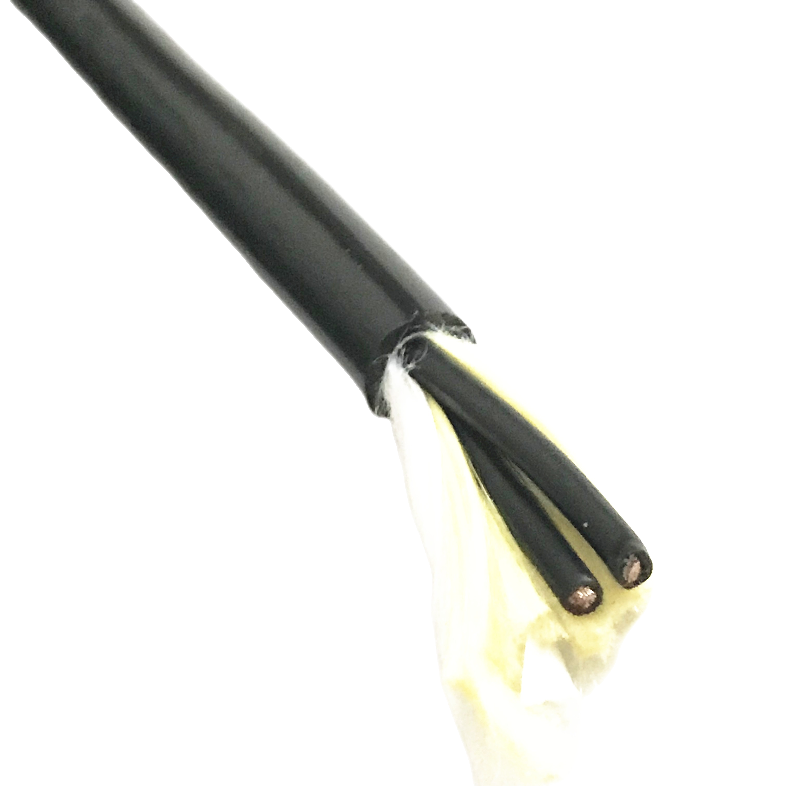
✅ Class 6 conductors — ≥ 196 wires per 0.75 mm² for continuous flex duty
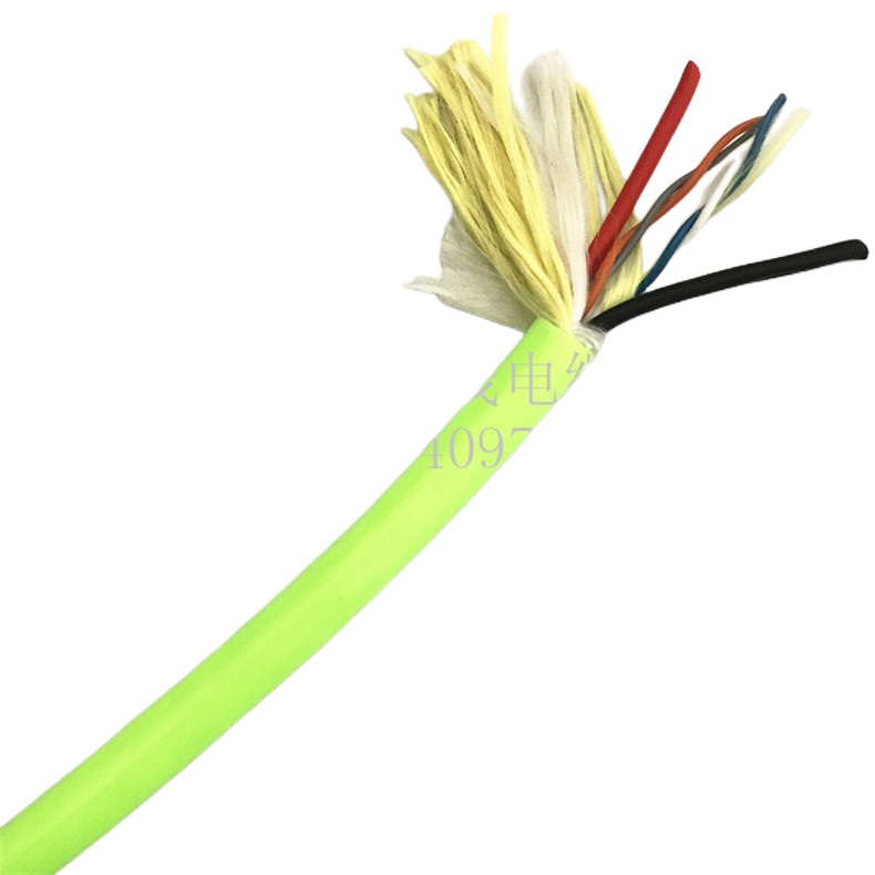
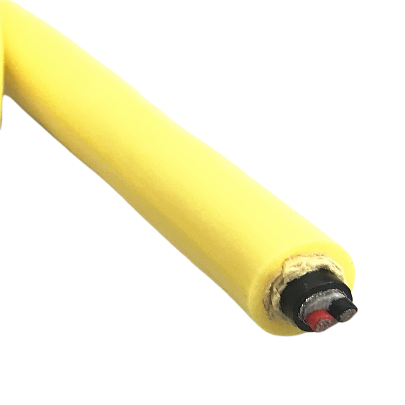
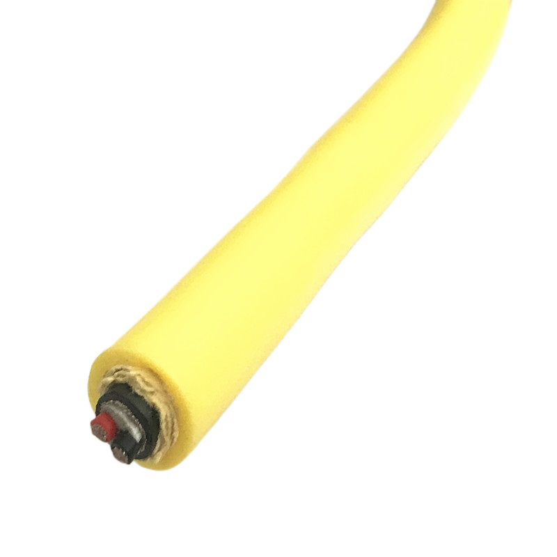
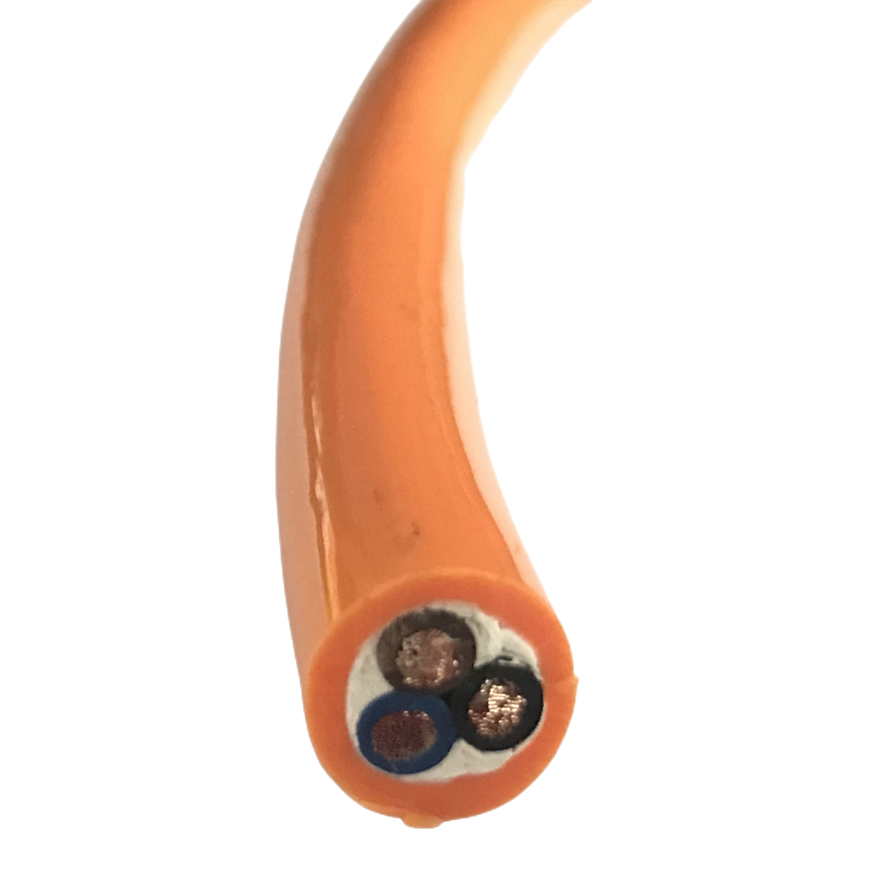
✅ Pair foil + overall braid option — dual-level EMI protection for analogue signals
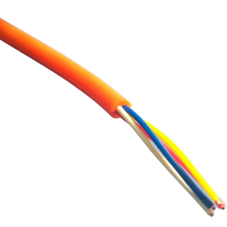
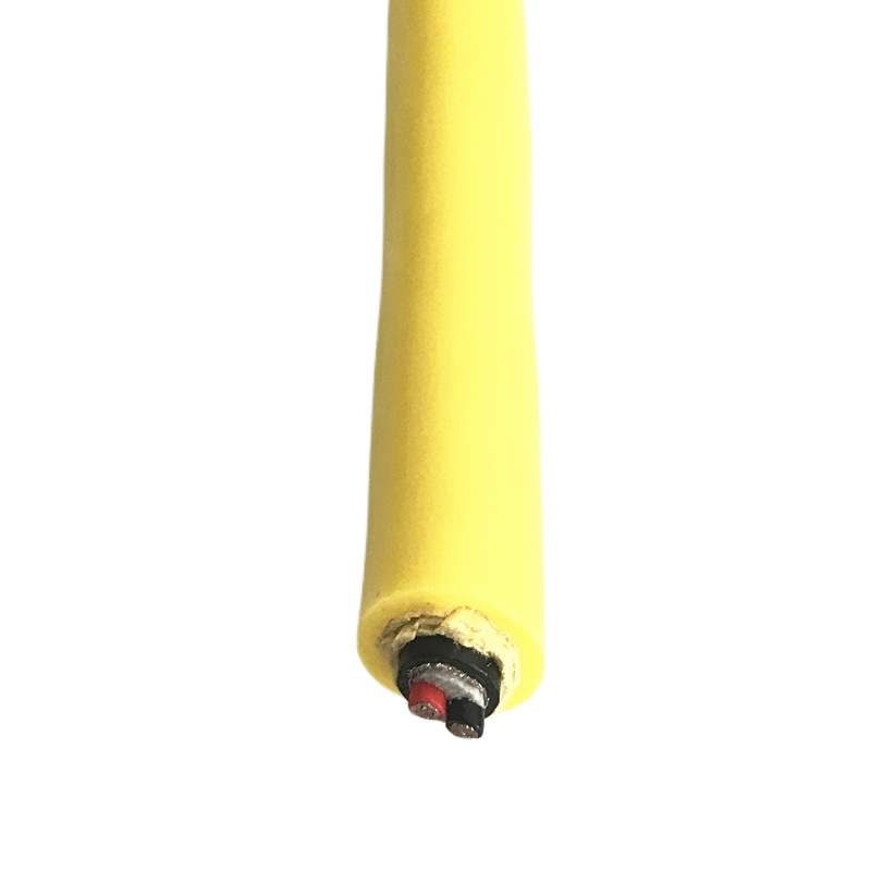
✅ PUR 92 Shore A jacket — oil resistant, −40 °C to +90 °C
✅ LSZH variant available — IEC 60332-3 rated for enclosed panels and clean rooms
PUR Shielded Flexible Cable for Industrial Automation EMI Protection High Flex Cable Manufacturer
A PUR shielded flexible cable fails for one of two reasons: the shield fails mechanically before the conductors do, or the shield was never adequate for the electromagnetic environment it was installed in. Both failures are preventable — the first through correct shielding architecture for the flex application, the second through correct shielding performance specification for the interference source.
Rousheng’s RST-SH series addresses both failure modes. The shielding system is designed for continuous flexing, not static installation — braid weave angle, coverage, and drain wire geometry are all specified to maintain transfer impedance below 30 mΩ/m at 1 MHz through 5,000,000 flex cycles, not just at installation.
This page covers the EMI shielding performance data, product variants for different automation environments, full technical specification, application-specific model selection, and field diagnostic guidance for the most common shielded cable failures in PLC and servo drive wiring.
|
Transfer impedance |
Braid coverage |
Flex life |
Jacket |
Voltage |
|
< 30 mΩ/m |
≥ 90% optical |
≥ 5,000,000 |
PUR 92 Shore A |
300 / 500 V AC |
|
@ 1 MHz, 5M flex cycles |
Tinned Cu braid |
At 4× OD bend radius |
Oil & abrasion resistant |
IEC 60227 rated |
The EMI Problem That Shielded Flexible Cable Must Solve in Automation Wiring
Why EMI shielding fails in flexible cable installations
Variable-frequency drives (VFDs) and servo amplifiers generate common-mode noise at switching frequencies of 4–16 kHz and their harmonics up to several MHz. When this noise couples into unshielded or inadequately shielded control signal cables — encoder wires, analogue 4–20 mA loops, thermocouples, PLC I/O wiring — it produces measurement errors, spurious axis movements, and false fault triggers that are expensive to diagnose and nearly impossible to reproduce on demand.
Shielding against VFD common-mode noise requires low transfer impedance at 1 MHz and above — not just high DC coverage percentage. A cable marketed as “90% shield coverage” may have a transfer impedance of 150 mΩ/m at 1 MHz due to inductance in the braid — twelve times higher than the RST-SH specification.
The second failure mode is mechanical: a braid shield designed for static installation loses optical coverage and gains transfer impedance when flexed repeatedly. After 500,000 flex cycles, a standard braid optimised for coverage degrades from 88% to 65% coverage, with transfer impedance rising from 45 mΩ/m to > 200 mΩ/m — effectively unshielded at the frequencies that matter.
How RST-SH maintains PUR shielded flexible cable performance through 5M cycles
Three design parameters determine whether a shielded cable’s EMI performance survives long-term flexing:
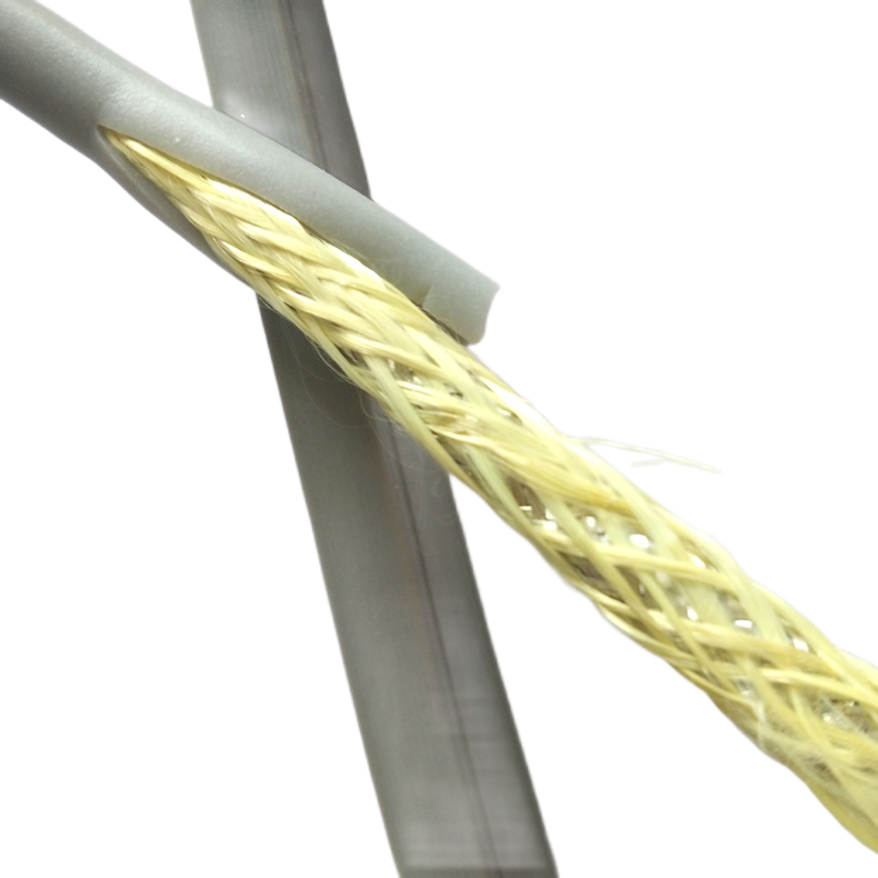
- Braid weave angle: RST-SH uses 32–38° weave angle — the range that prevents wire-to-wire contact under flexing while maintaining optical coverage above 88% at 4× OD bend radius. Angles below 28° collapse on the bend inside; angles above 42° cause braid wire abrasion.
- Drain wire contact: the drain wire is bonded to the braid at 80 mm intervals using a conductive tape wrap — preventing the drain wire from separating from the braid under repeated flexing and causing an impedance discontinuity that is visible as a noise spike at the PLC input.
- Filler geometry: inter-core voids are filled with foamed PE elements that prevent the shield from being compressed against the insulated cores during bending. Direct contact between braid and insulation under flexing causes localised shield distortion that raises transfer impedance by 40–80 mΩ/m within 200,000 cycles.
|
TRANSFER IMPEDANCE DATA |
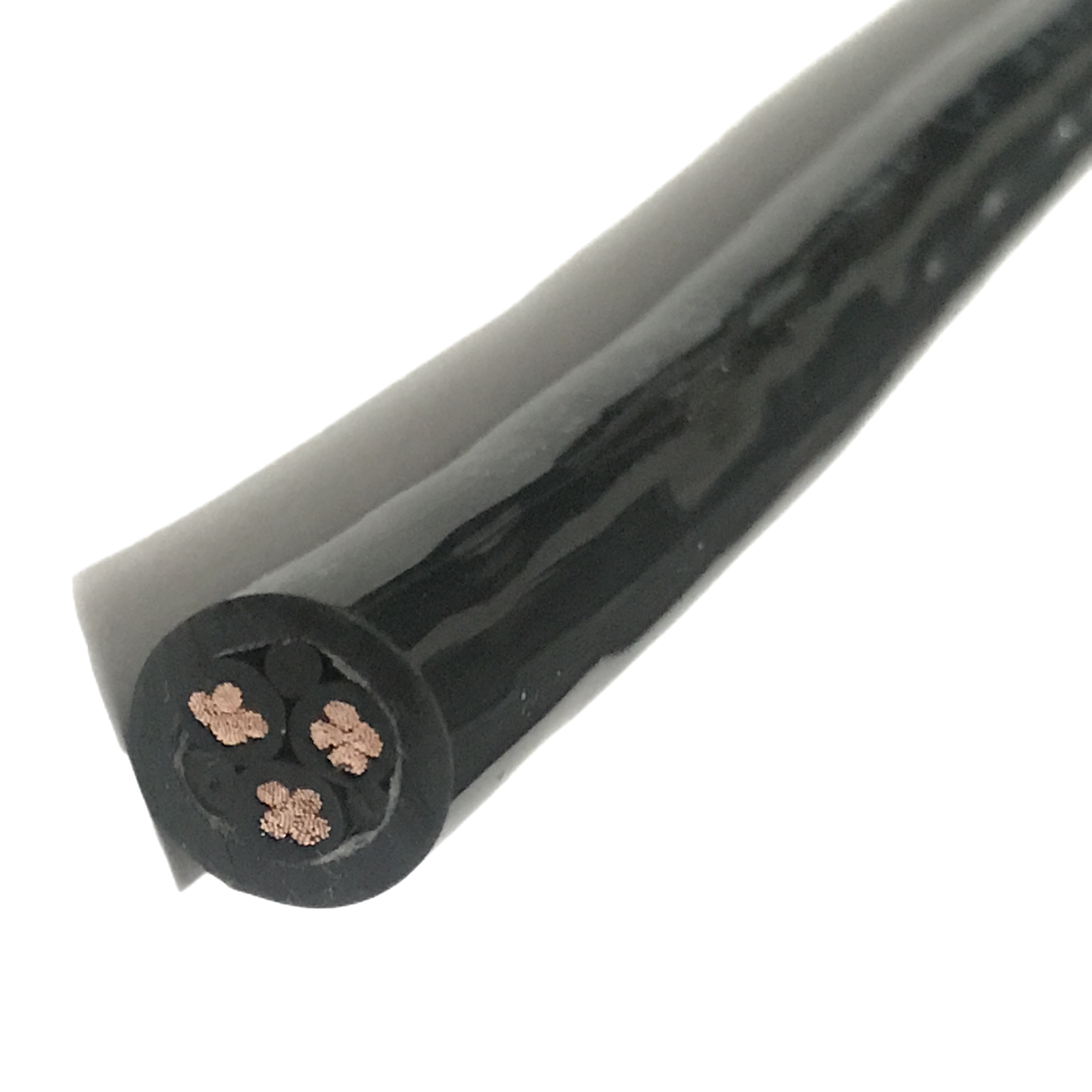
RST-SH-220 (4 × 0.75 mm², overall Cu braid) — measured per IEC 62153-4-3: 0 cycles: 18 mΩ/m · 500k cycles: 21 mΩ/m · 2M cycles: 26 mΩ/m · 5M cycles: 29 mΩ/m Comparison: standard PVC shielded flexible cable at same flex protocol — TI at 5M cycles: 210 mΩ/m (7× higher than RST-SH at end of life). |
RST-SH Series Product Matrix
PUR shielded flexible cable — standard configurations for industrial automation
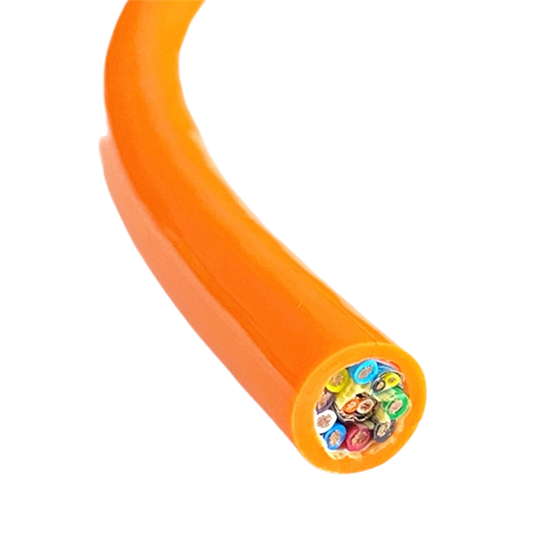
Twelve standard models covering overall-shielded, individually-pair-shielded, and combined power-plus-signal configurations. All models: IEC 60228 Class 6 conductors, PUR 92 Shore A jacket, ≥ 5,000,000 flex cycles at 4× OD.
|
Model |
Cores × mm² |
Shield type |
Flex life |
TI @ 1 MHz |
OD (mm) |
Temp °C |
Use / jacket |
|
RST-SH-110 |
4 × 0.34 mm² |
Cu braid overall |
≥5M |
< 30 mΩ/m |
6.8±0.3 |
−40/+90 |
PUR · signal |
|
RST-SH-120 |
4 × 0.75 mm² |
Cu braid overall |
≥5M |
< 30 mΩ/m |
8.5±0.3 |
−40/+90 |
PUR · control |
|
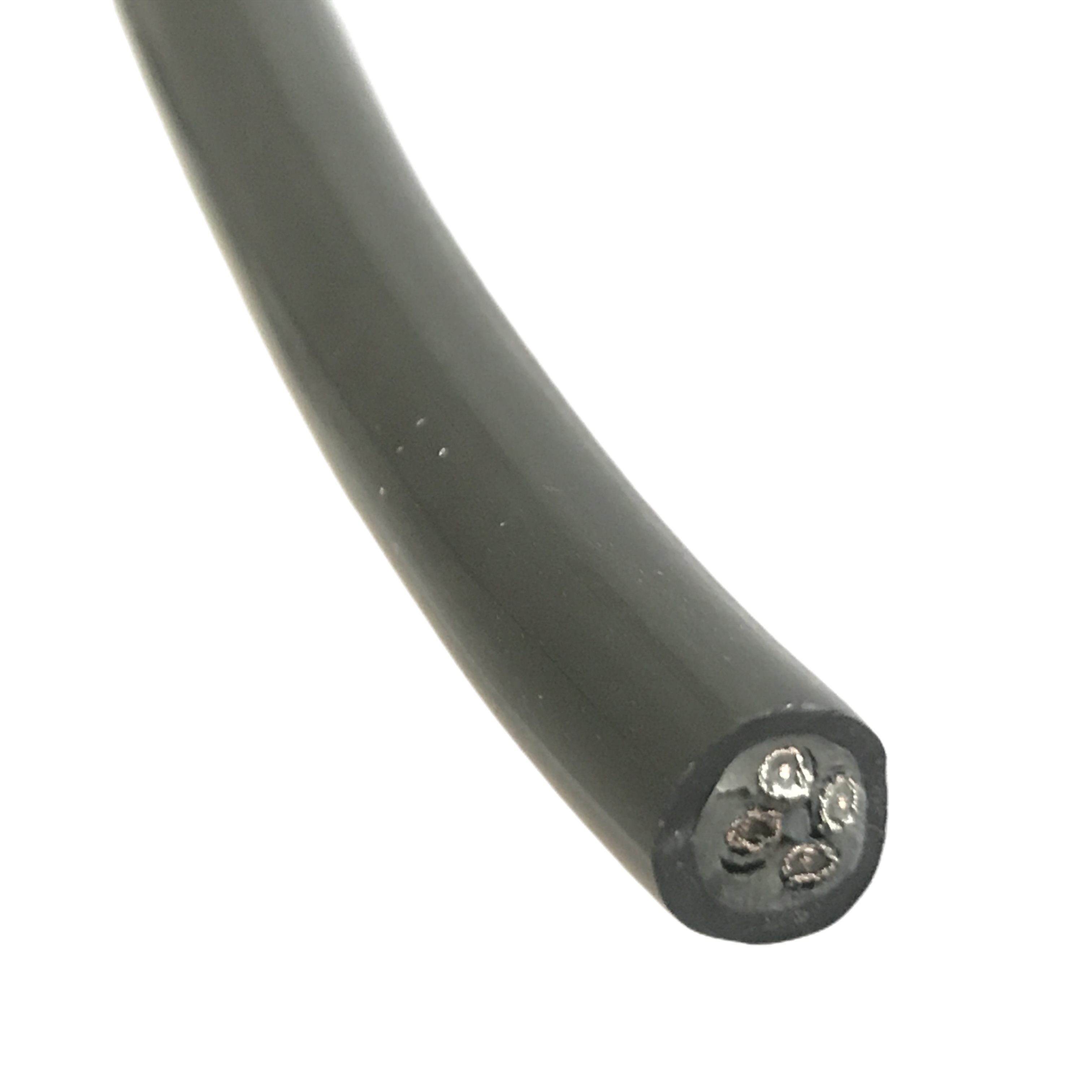
RST-SH-130 |
7 × 0.75 mm² |
Cu braid overall |
≥5M |
< 30 mΩ/m |
10.8±0.3 |
−40/+90 |
PUR · I/O |
|
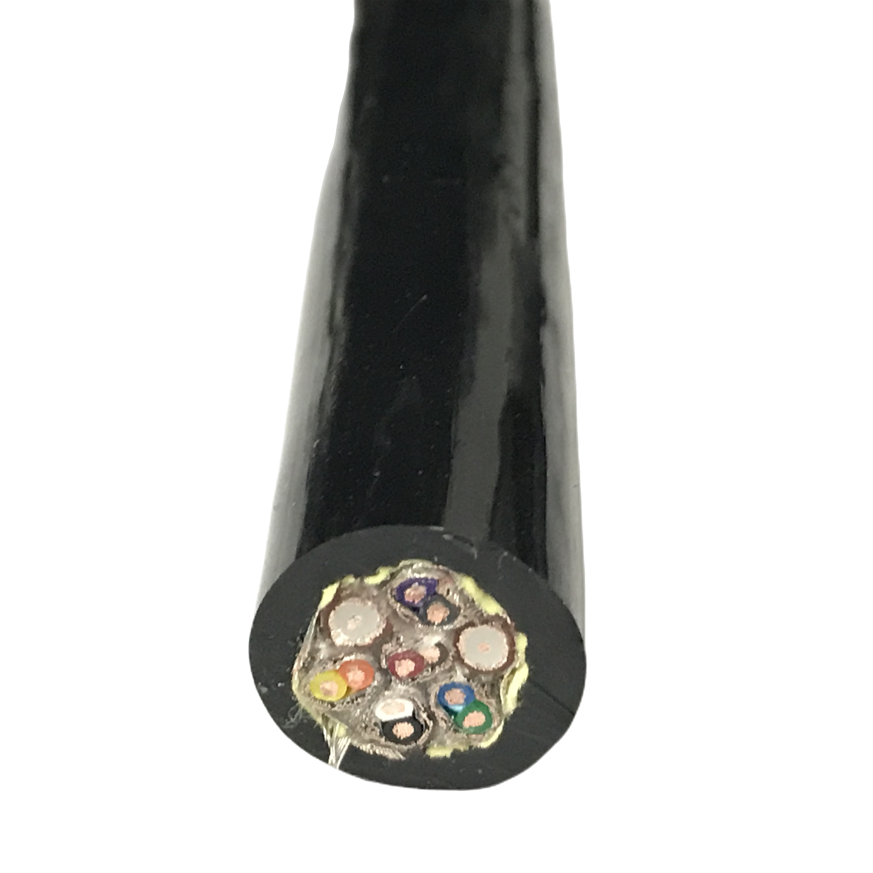
RST-SH-140 |
12 × 0.75 mm² |
Cu braid overall |
≥5M |
< 30 mΩ/m |
13.5±0.4 |
−40/+90 |
PUR · multi-core |
|
RST-SH-210 |
2 pr × 0.75 mm² |
Foil/pr + braid |
≥5M |
< 20 mΩ/m |
9.2±0.3 |
−40/+90 |
PUR · analogue |
|
RST-SH-220 |
4 pr × 0.75 mm² |
Foil/pr + braid |
≥5M |
< 20 mΩ/m |
13.0±0.4 |
−40/+90 |
PUR · multi-pair |
|
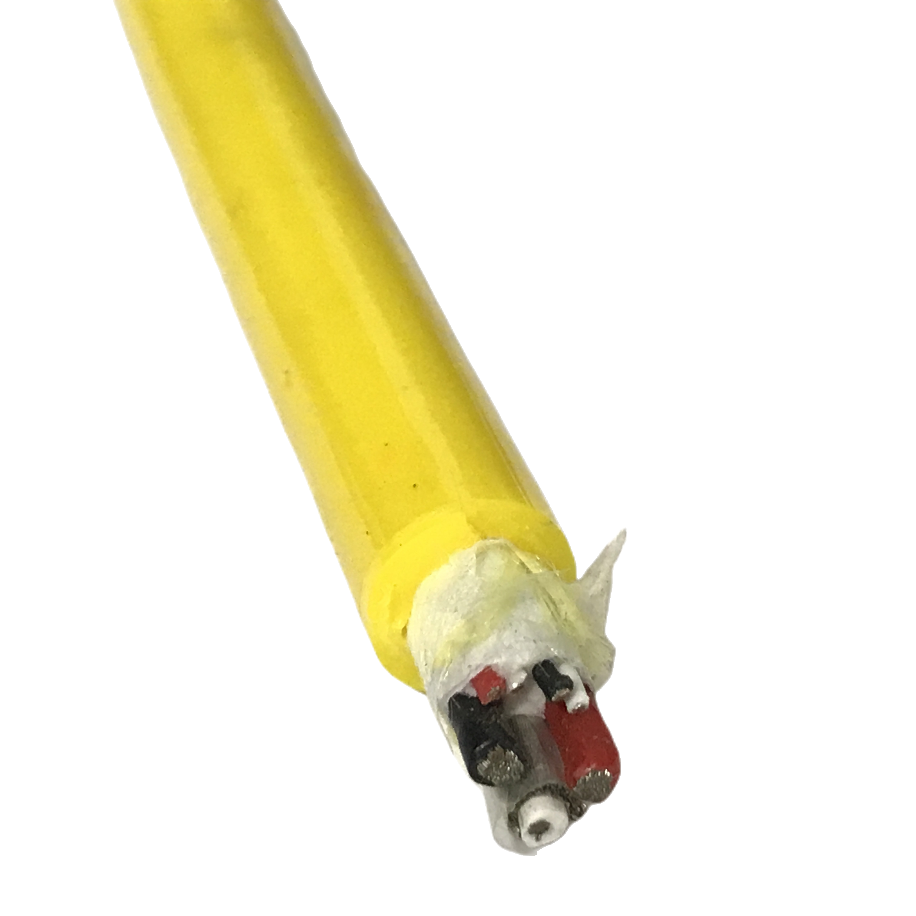
RST-SH-230 |
2 pr × 0.34 mm² |
Foil/pr + braid |
≥5M |
< 20 mΩ/m |
7.5±0.3 |
−40/+90 |
PUR · sensor/TC |
|
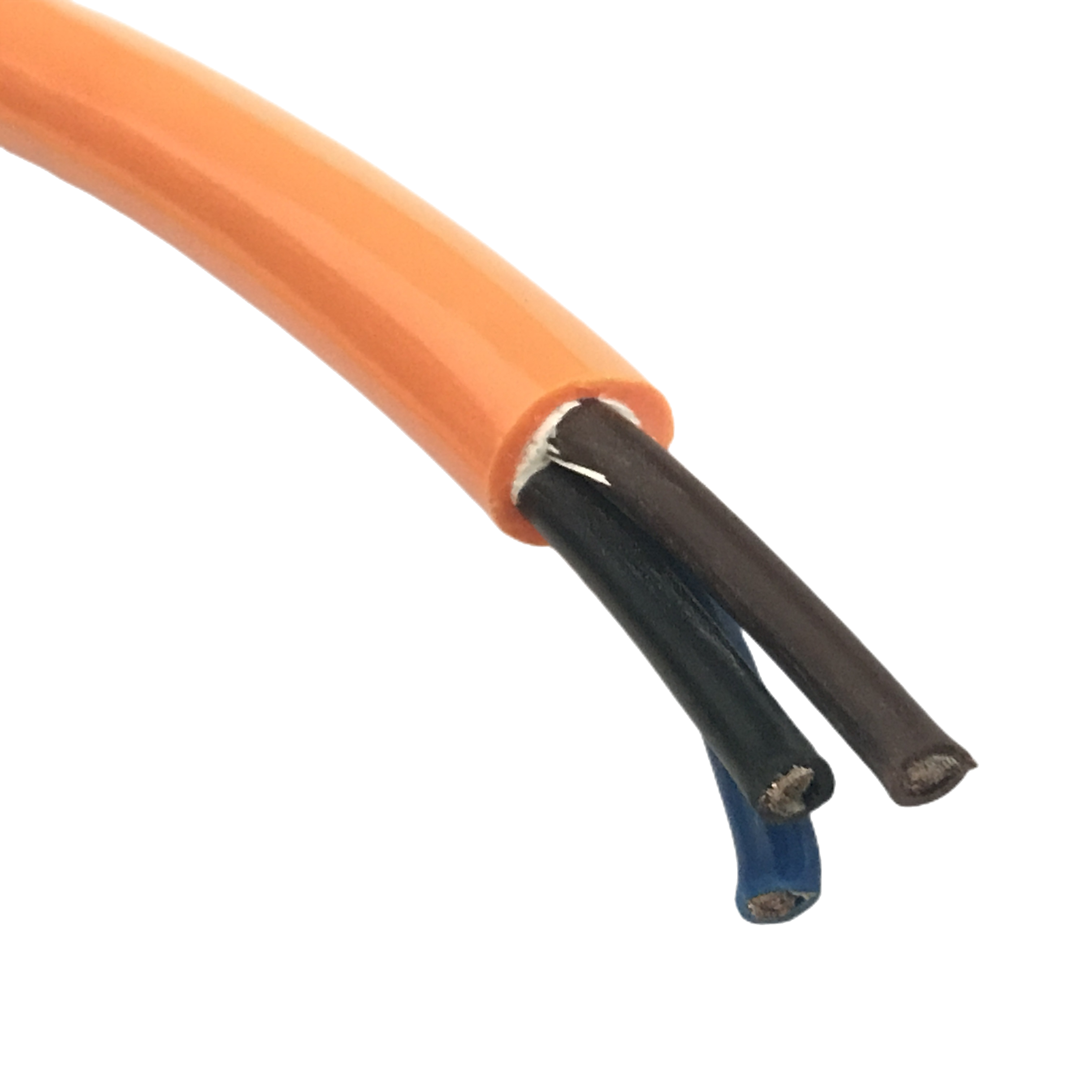
RST-SH-310 |
3×1.5 + 4×0.75 mm² |
Signal braid |
≥5M |
< 30 mΩ/m |
14.2±0.4 |
−40/+90 |
PUR · power+ctrl |
|
RST-SH-320 |
3×2.5 + 2pr×0.75 |
Pair foil + braid |
≥5M |
< 20 mΩ/m |
16.0±0.5 |
−40/+90 |
PUR · servo+feedback |
|
RST-SH-410 |
4 × 0.75 mm² |
Cu braid overall |
≥4M |
< 35 mΩ/m |
9.0±0.3 |
−25/+80 |
LSZH · panel/clean |
|
RST-SH-420 |
7 × 0.75 mm² |
Foil/pr + braid |
≥4M |
< 25 mΩ/m |
11.5±0.4 |
−25/+80 |
LSZH · enclosed |
|
RST-SH-C (ETO) |
Per spec |
Per spec |
Per design |
Per design |
5–30 mm |
Per jacket |
PUR/LSZH/TPE |
Model notes: RST-SH-210/220/230 pair-shielded models use individual AL/PET foil per pair (100% coverage) plus overall tinned Cu braid — dual-level shielding provides 8–10 dB additional isolation between pairs compared to overall-braid-only models. Required for 4–20 mA analogue loops and thermocouple signals where inter-pair crosstalk is as damaging as external EMI. LSZH models (RST-SH-410/420) have 4M cycle flex life — LSZH compounds are less elastic than PUR at equivalent hardness.
Complete Technical Specification
Conductor — IEC 60228 Class 6 ultra-fine stranding
|
Parameter |
Specification |
|
Wire count |
0.34 mm²: ≥130 wires · 0.75 mm²: ≥196 wires · 1.5 mm²: ≥280 wires · 2.5 mm²: ≥380 wires |
|
Individual wire diameter |
≤ 0.10 mm; below the copper endurance limit at 4× OD dynamic bend radius and rated flex life |
|
Conductor material |
Oxygen-free copper (OFC) per ASTM B170; tin-plated option available for humid or oil-immersion environments |
|
DC resistance @ 20°C |
0.34 mm²: ≤56.0 Ω/km · 0.75 mm²: ≤25.5 Ω/km · 1.5 mm²: ≤13.7 Ω/km · 2.5 mm²: ≤8.21 Ω/km |
|
Rated voltage |
300/500 V AC (control and signal cores); 450/750 V AC (power cores in RST-SH-3xx combined models) |
Shielding architecture and EMI performance
|
Parameter |
Specification |
|
Overall braid material |
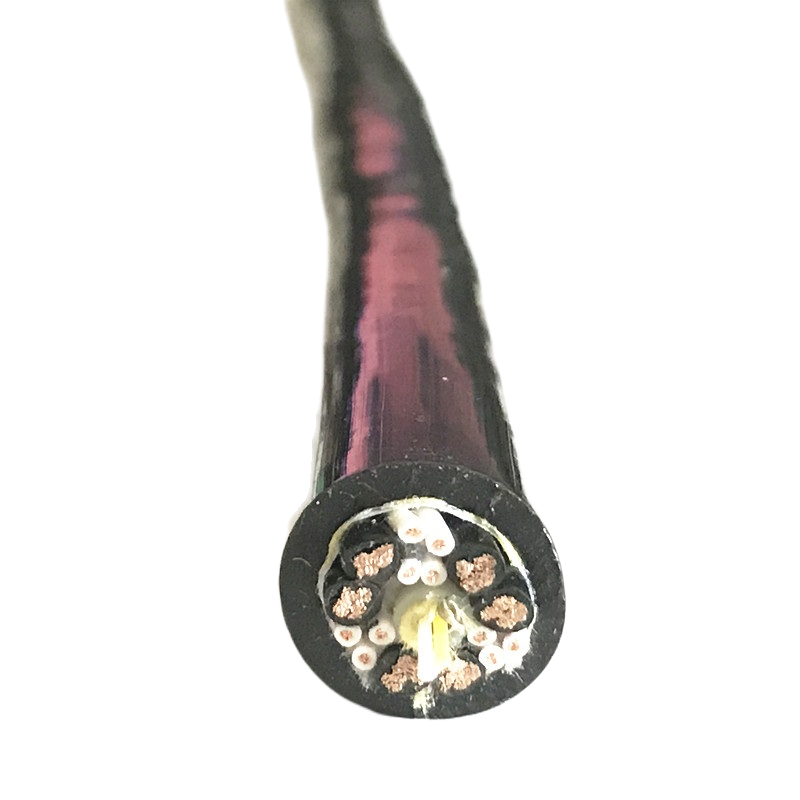
Tinned copper braid; optical coverage ≥ 90%; braid weave angle 32–38° — validated range for maintaining coverage ≥ 88% at 4× OD bend radius over 5M cycles |
|
Individual pair shield |
AL/PET foil, 100% coverage, bonded to polyester carrier; drain wire 0.5 mm² OFC bonded to foil at 80 mm intervals |
|
Transfer impedance @ 1 MHz |
Overall braid only: < 30 mΩ/m (initial); < 35 mΩ/m (after 5M cycles). Pair foil + overall braid: < 20 mΩ/m (initial); < 25 mΩ/m (after 5M cycles). Measured per IEC 62153-4-3 |
|
Shielding effectiveness |
≥ 55 dB at 1 MHz; ≥ 40 dB at 30 MHz (per IEC 62153-4-6); suitable for IEC 61000-4-3 radiated immunity test environments at 10 V/m |
|
Drain wire continuity |
Drain wire resistance ≤ 50 mΩ/m; bonded to braid at 80 mm intervals; verified after 5M flex cycles — drain separation from braid is the most common shielded cable failure mode and is specifically tested |
|
Shield grounding |
Single-end ground (preferred for analogue signal cables — eliminates shield current from flowing through the signal reference plane). Both-ends ground acceptable for digital signal cables and power-plus-signal combined cables |
Insulation, jacket, and mechanical parameters
|
Parameter |
Specification |
|
Core insulation |
Semi-rigid PVC, 300/500 V rated; 0.5–0.7 mm wall; colour-coded per IEC 60446. XLPE option for oil-immersion environments |
|
Filler elements |
Foamed PE filler between cores; maintains circular cross-section within ± 3% ovality at rated flex life. Prevents braid-to-insulation contact that raises transfer impedance |
|
Outer jacket — PUR |
92 Shore A; −40°C to +90°C; Taber abrasion 15 mg / 1,000 cycles (CS-10, 500 g); oil-resistant per IEC 60811-2-1 Group 1 (tensile retention ≥ 80% after 7-day immersion at 70°C) |
|
Outer jacket — LSZH |
−25°C to +80°C; IEC 60754-1 halogen-free (< 0.5% HCl equivalent); IEC 61034-2 smoke density ≥ 60% light transmission; IEC 60332-3-22 flame retardancy |
|
Flex life |
PUR models: ≥ 5,000,000 cycles at 4× OD dynamic bend radius. LSZH models: ≥ 4,000,000 cycles. Criterion: no conductor break, resistance change < 10%, TI < 35 mΩ/m at 1 MHz |
|
Min dynamic bend radius |
4× OD (overall braid models); 5× OD (pair-shielded models — foil layer adds stiffness); 4× OD (LSZH models at operating temperature ≥ 0°C) |
|
Chemical resistance |
PUR: resistant to mineral oil, hydraulic fluid, cutting coolant, dilute acid (pH ≥ 4), dilute alkali (pH ≤ 10). Not resistant to concentrated aromatic solvents, ketones |
EMC Application Guide: Matching Shield Architecture to Interference Source
Selecting PUR shielded cable by interference type and signal category
The correct shielding architecture depends on the nature of the interference source and the signal type being protected. Using a single-layer overall braid for a thermocouple signal adjacent to a VFD is insufficient — the analogue signal requires pair-level isolation. Using dual-pair shielding for a digital PLC I/O cable is over-specified — an overall braid is adequate and simpler to terminate.
|
Signal type |
Interference source |
Required shielding |
Recommended model |
Grounding method |
|
Digital PLC I/O (24 V DC) |
Contactor switching, relay noise |
Overall braid — single-ended ground |
RST-SH-120 / 130 |
Ground at PLC cabinet end only |
|
4–20 mA analogue loop |
VFD common-mode noise, 4–16 kHz |
Pair foil + overall braid — single-ended ground |
RST-SH-210 / 220 |
Ground foil drain at receiver end; float at transmitter |
|
Thermocouple / PT100 sensor |
VFD, high-frequency switching |
Pair foil + overall braid — single-ended ground |
RST-SH-230 |
Ground at controller end; float at sensor end |
|
Encoder / SSI position feedback |
Servo drive switching, motor current |
Pair foil + overall braid; TI < 20 mΩ/m |
RST-SH-220 |
Ground at drive end; verify motor chassis isolated from signal reference |
|
Servo power + I/O combined |
Motor current harmonics, drive switching |
Signal section: pair foil + braid; Power section: separate unshielded |
RST-SH-320 |
Shield at drive cabinet end; verify no shield current path through motor frame |
|
Safety relay / E-stop circuit |
General industrial EMI, relay transients |
Overall braid — both-ends ground permissible (digital, non-sensitive) |
RST-SH-110 / 120 |
Both ends to safety controller earth rail |
|
SHIELD GROUNDING RULE |
Single-end ground (signal cable standard): prevents shield from becoming a conductor for ground-loop current. Applies to all analogue, thermocouple, and encoder cables. Both-ends ground: only for digital signal cables where the cable length creates a significant impedance path — typically > 30 m in high-noise environments. Both-ends grounding on analogue cables introduces ground-loop noise that negates the shielding benefit. |
Installation Environment Guide
Matching PUR shielded flexible cable jacket to the automation environment
The jacket compound determines the cable’s suitability for the physical environment — not the shielding performance. Shielding performance is consistent across PUR and LSZH models; the jacket choice is driven by chemical, temperature, and flame-retardancy requirements.
|
Environment |
Jacket |
Recommended model |
Selection rationale |
|
Flexible cable conduit / cable track |
PUR |
RST-SH-1xx / 2xx |
Standard installation in drag chain or cable track alongside servo and VFD wiring; PUR jacket resists oil mist and abrasion at chain link contact points |
|
Control cabinet internal wiring |
LSZH |
RST-SH-410 / 420 |
Enclosed panel wiring where IEC 60332-3 flame retardancy and low smoke emission are required by electrical safety regulations; LSZH jacket mandatory in many EU and UK panel builds |
|
Machine tool / CNC coolant splash |
PUR (oil-rated) |
RST-SH-120 / 220 |
Cutting fluid splash and hydraulic oil mist require PUR oil resistance per IEC 60811-2-1 Group 2; PVC jacket degrades within 6 months in this environment |
|
Semiconductor clean room |
LSZH low-outgassing |
RST-SH-C ETO |
Standard LSZH may still outgas at elevated temperatures. Specify ultra-low-outgassing LSZH ETO compound for ISO Class 5–7 clean rooms; confirm total organic compound (TOC) requirement at order |
|
Food processing / washdown |
PUR (FDA-compliant option) |
RST-SH-C ETO |
High-pressure washdown with alkaline cleaners (pH 10–12) requires FDA 21 CFR 177.2600 jacket compound; standard PUR handles pH ≤ 10 only. Confirm cleaning agent pH and temperature at order |
|
Outdoor / UV-exposed installation |
PUR (UV-stabilised) |
RST-SH-1xx / 2xx PUR |
PUR UV-stabilised grade withstands 1,000+ hours outdoor UV per ISO 4892-2 without surface chalking. PVC degrades within 6–18 months of direct outdoor UV exposure |
Field Diagnostic Reference: Shielded Flexible Cable Failures in Automation
Diagnosing EMI and mechanical failures in PUR shielded cable installations
These five failure patterns account for the large majority of shielded flexible cable complaints received by Rousheng’s application engineering team. Each includes the specific measurement needed to confirm the root cause — not just the symptom.
|
Symptom |
Root cause |
Measurement |
Confirming threshold |
Correction |
|
VFD noise on 4–20 mA analogue loop — noise level correlates with motor speed |
Overall braid only — insufficient isolation between analogue pairs and VFD common-mode noise |
Clamp current meter on cable outer braid — measure shield current at rated motor speed |
Shield current > 50 mA at motor full speed = inadequate shielding for analogue signal |
Replace with RST-SH-210/220 (pair foil + braid). Verify single-end grounding: floating the shield at the sensor end eliminates ground-loop current as a separate noise source. |
|
Intermittent signal loss after 6–12 months — cable passes bench test |
Drain wire separation from braid under repeated flexing — TI rises intermittently at bend reversal point |
Transfer impedance measurement per IEC 62153-4-3 at flex mid-point vs straight section |
TI difference > 30 mΩ/m between flex point and straight = drain wire separation |
Replace with RST-SH series — drain bonded at 80 mm intervals. Verify minimum bend radius in installation: pair-shielded models require 5× OD minimum, not 4× OD. |
|
PLC input reads correctly during commissioning, fails after 3 months in service |
Ground loop introduced by both-ends shield grounding on analogue cable — 50 Hz current in shield couples into signal |
Disconnect shield at one end (temporarily). If signal recovers: ground loop confirmed |
Signal recovery on one-end-only grounding = ground loop. Signal does not recover = external noise source |
Float shield at sensor/transmitter end; ground only at PLC cabinet. Re-check cable routing — cables running parallel to power cables for > 300 mm should be rerouted or separated by a grounded metal divider. |
|
Shielded cable jacket cracking after 12 months — no mechanical damage visible |
PVC jacket UV degradation — cable installed in direct outdoor sunlight without conduit |
UV chalking test: run fingernail across jacket surface — chalk residue confirms UV degradation |
Any surface chalking = UV degradation in progress |
Replace with RST-SH PUR UV-stabilised jacket. PVC shielded cable must not be used in direct outdoor UV exposure. PUR withstands 1,000+ hours outdoor UV without chalking or cracking. |
|
Encoder position error at high speed — error magnitude proportional to speed |
Insufficient shielding at encoder cable — motor drive switching noise at 8–16 kHz coupling into encoder signal |
Oscilloscope on encoder signal line with motor running at rated speed vs motor stopped |
Noise > 100 mV peak-to-peak on encoder line at rated motor speed = insufficient shielding |
Replace with RST-SH-220 (pair foil + overall braid, TI < 20 mΩ/m). Verify encoder cable is not bundled with motor power cable — maintain ≥ 100 mm separation or route through separate conduit. |
Frequently Asked Questions
What makes a PUR shielded flexible cable different from a standard shielded cable?
A standard shielded cable is designed for static installation — its braid is optimised for coverage at rest. After repeated flexing, the braid geometry shifts, coverage drops, and transfer impedance rises. RST-SH PUR shielded cables use a braid weave angle (32–38°) validated to maintain ≥ 88% coverage at 4× OD bend radius over 5,000,000 cycles. The drain wire is also bonded to the braid at 80 mm intervals — preventing the drain separation that causes intermittent shield faults in standard cables after 6–12 months of flex service.
Should I use single-end or both-ends shield grounding?
Use single-end grounding for all analogue signal cables (4–20 mA, thermocouple, PT100, encoder) — ground the shield at the receiving/controller end only. Both-ends grounding on analogue cables creates a ground loop that introduces 50 Hz and its harmonics directly into the signal, negating the shielding benefit. Use both-ends grounding for digital signal cables longer than 30 m in high-noise environments, and for power-plus-signal combined cables where the shield must carry chassis ground current.
How do I verify that a shielded cable is performing correctly after installation?
Measure transfer impedance at 1 MHz using the triaxial test method per IEC 62153-4-3. A correctly performing RST-SH cable reads < 30 mΩ/m initially and < 35 mΩ/m after the rated flex life. Alternatively, use a clamp current meter on the outer braid to measure shield current during machine operation — above 50 mA shield current on an analogue cable indicates the shield is carrying return current that should be rerouted or the grounding scheme is incorrect.
Can RST-SH cables be used in drag chain systems?
Yes. All RST-SH PUR models are rated ≥ 5,000,000 cycles at 4× OD (overall braid models) or 5× OD (pair-shielded models) — both within normal drag chain operating conditions. Confirm that the chain inner radius meets the cable minimum bend radius. The RST-SH-3xx combined power-plus-signal models are suitable for drag chain wiring where servo power and feedback must share the same cable trough.
What is the difference between RST-SH and RST-DC drag chain cables?
RST-DC is the dedicated drag chain series — unshielded, optimised for maximum flex life (10,000,000 cycles) at minimum OD. RST-SH is the shielded series — same Class 6 conductors and PUR jacket, with an added EMI shielding system that reduces flex life to 5,000,000 cycles and increases OD by 1.5–2.0 mm. Use RST-DC where shielding is not required; use RST-SH where the cable runs adjacent to VFDs, servo drives, or other high-frequency switching sources that require EMI attenuation.
Request Samples, EMC Test Data, or a Quotation
Getting the right PUR shielded cable specified for your automation system
Rousheng provides free EMC application review — interference source identification, shield architecture recommendation, and grounding scheme guidance — before order placement. Cable samples with transfer impedance test reports are available on request.
For a complete single-reply response, include:
- Signal type(s) to be protected: analogue, digital, encoder, thermocouple, or combined
- Interference source: VFD frequency and switching frequency, servo drive type, relay/contactor voltage
- Cable routing: drag chain, static installation, outdoor, or panel internal wiring
- Core count and cross-section required (or list of signals and current ratings)
- Installation environment: oil splash, coolant immersion, clean room, washdown, outdoor UV
- Required flame retardancy: IEC 60332-1 (PUR standard) or IEC 60332-3 (LSZH)
- Flex cycle requirement and minimum bend radius in your installation
- Quantity in metres on reel or cut lengths with connector type if pre-terminated
|
CONTACT |
Email: Jerry@rstlkable.com WhatsApp / Phone: +86 134 8219 7396 Address: No. 2591 Fengzhe Road, Fengxian District, Shanghai, China Sample requests: state RST-SH model, OD, and installation environment for targeted sample selection. |