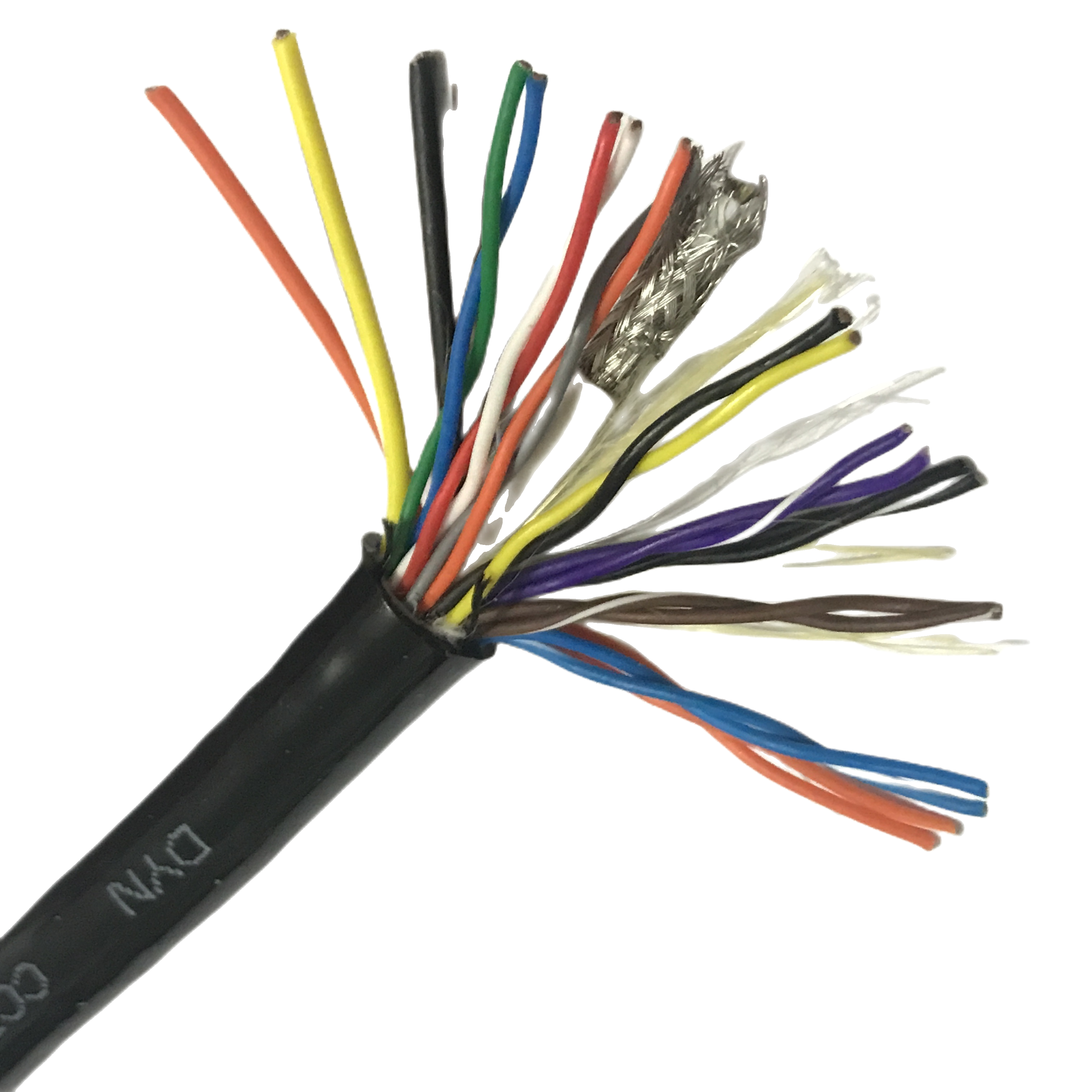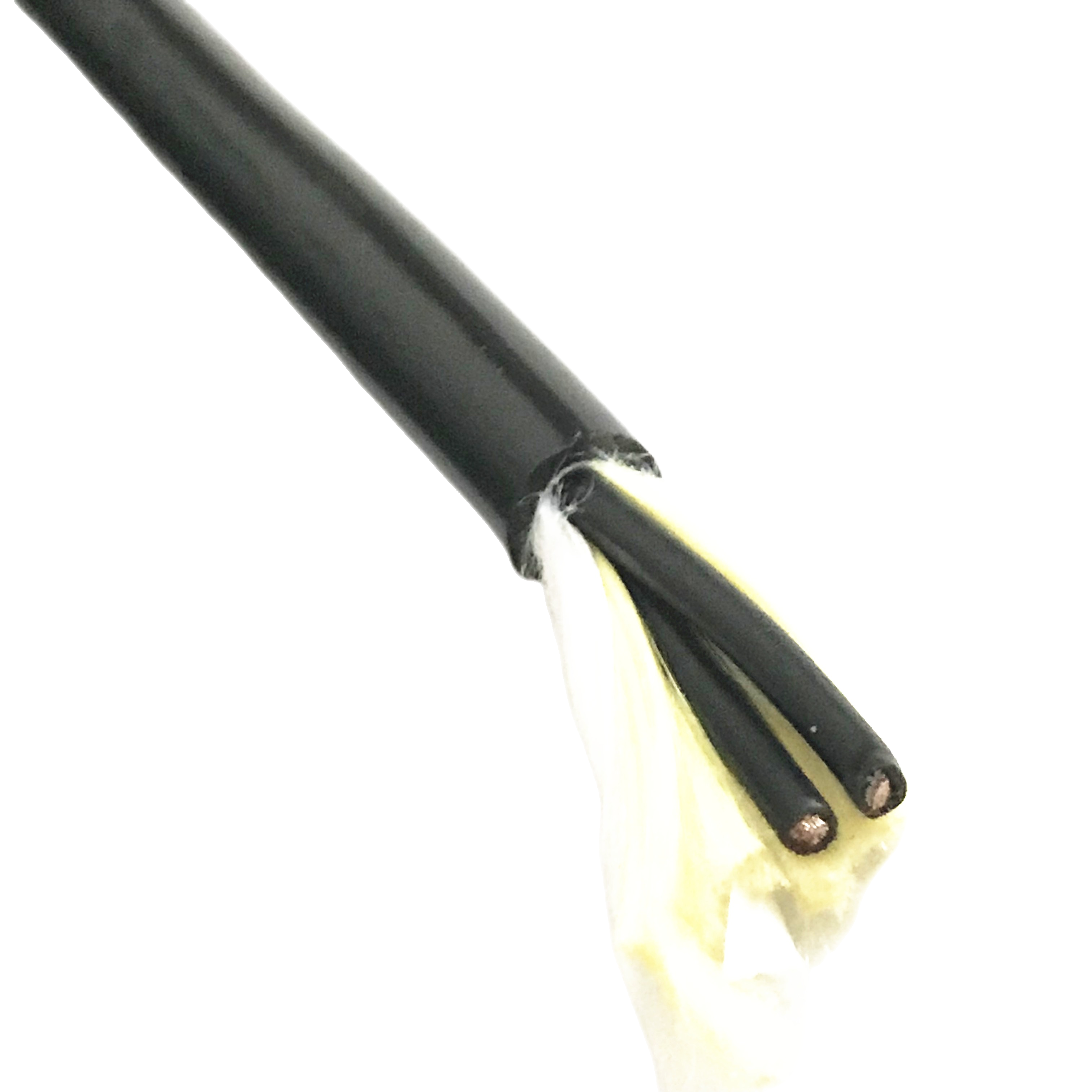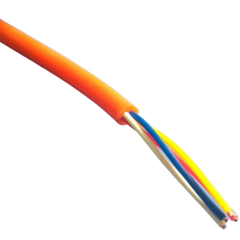
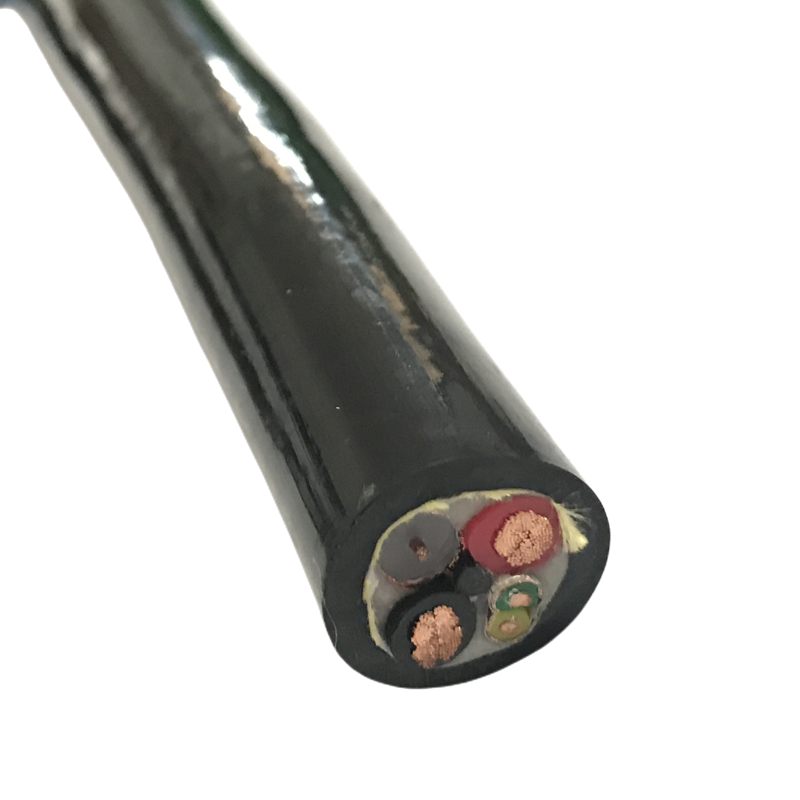
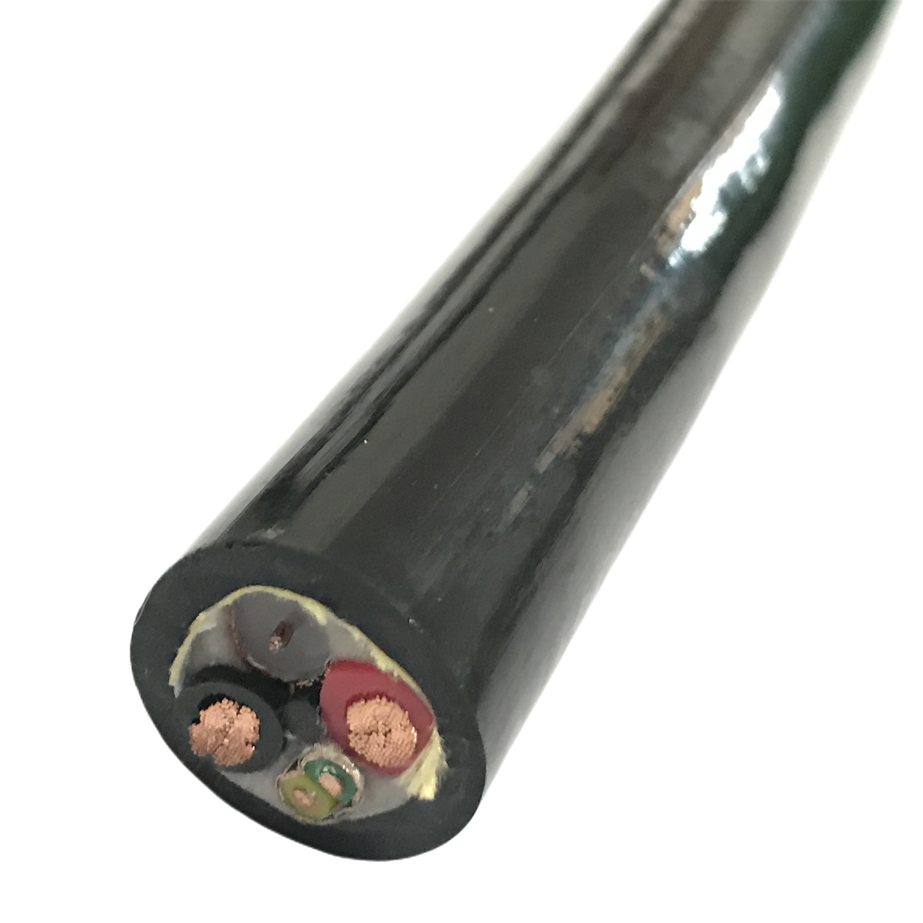
PUR Flexible Control Cable for Robotics Oil & Wear Resistant Continuous Motion Cable Supplier
The RST-RB series is a PUR flexible control cable designed for industrial robots and cobots, rated ≥5,000,000 cycles under simultaneous flex, torsion, and axial loading.
Key Benefits:
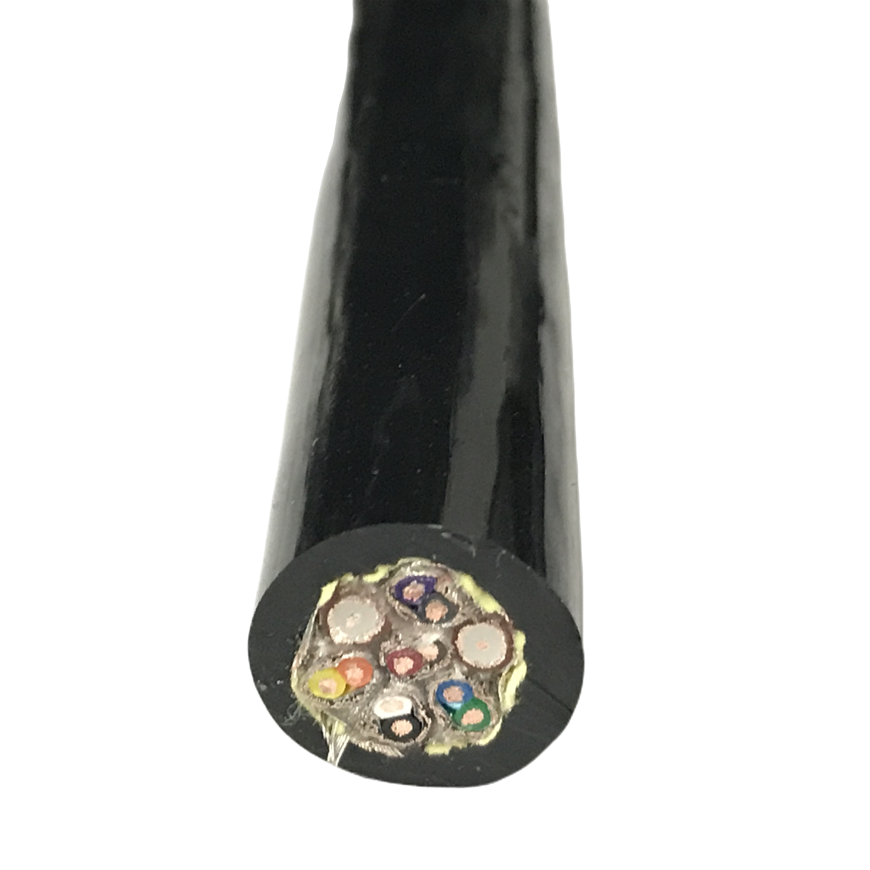
✅ Class 6 helical-lay conductors for multi-axis fatigue resistance
✅ Ether-type PUR jacket — oil resistant, no hydrolysis
✅ ±180°/m continuous bi-directional torsion rating
✅ RST-RB-500 cobot variant — ISO/TS 15066 compliant
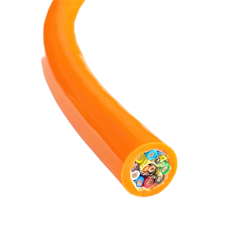
✅ Signal, control, encoder and power configurations available
PUR Flexible Control Cable for Robotics Oil & Wear Resistant Continuous Motion Cable Supplier
When a PUR flexible control cable fails at a robot wrist joint, the fault log usually shows an intermittent signal loss at a specific arm position — repeatable, not random. The cable passes continuity tests on the bench. It fails again in the same robot position during the next production shift. The cause is almost always a cable that was rated for single-axis flex, not the combined flex-torsion-extension loading that a robot wrist joint imposes simultaneously.
Rousheng’s RST-RB series was designed around this failure pattern. Every construction decision — helical conductor lay, elastomeric TPE core filler, 35° braid weave angle, ether-type PUR jacket — was derived from analysing why cables that pass drag chain qualification tests fail in robot arm applications. This page documents the measured performance data and the physical reasoning behind each decision.
Contents: construction architecture and quantified performance data; full product matrix; robot-joint selection guide including cobot-specific requirements; free-length calculation with asymmetric-axis worked examples; oil resistance by environment type; and field diagnostics for the most common multi-axis failure patterns.
|
Flex life |
Torsion rating |
Jacket compound |
Oil immersion |
Conductor |
|
≥ 5,000,000 |
±180° / m |
Ether-PUR 88A |
IEC 60811-2-1 Gr.2 |
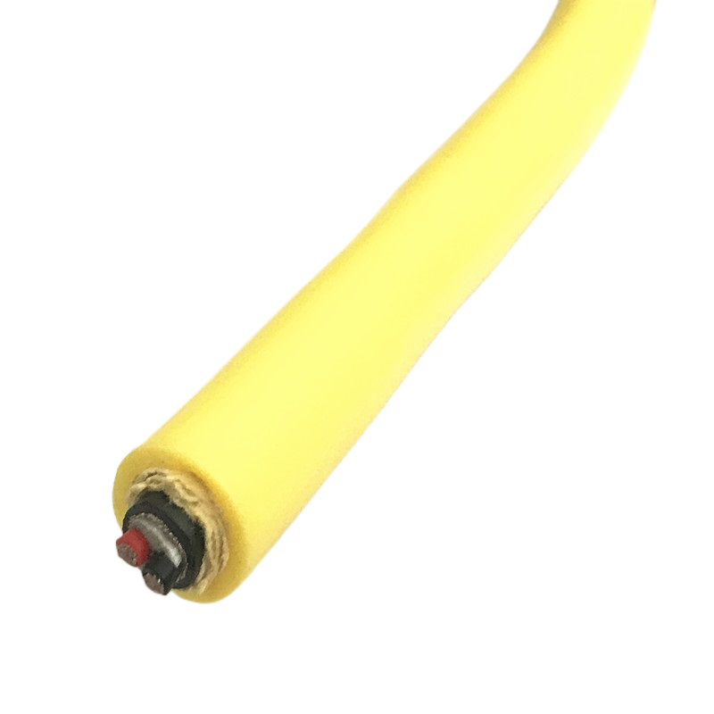
Class 6 / ≥196 wires |
|
Multi-axis combined load |
Bi-directional continuous |
Hydrolysis resistant |
≥ 70% tensile retention |
Ultra-fine OFC |
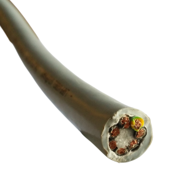
Construction Architecture: What Makes a PUR Flexible Control Cable Work Under Multi-Axis Loading
Why single-axis flex ratings do not transfer to robot applications
A cable rated for 10,000,000 cycles in a drag chain operates under a predictable, single-plane, constant-amplitude stress cycle. The outer conductors travel a longer path than the inner conductors on every bend — but this differential is fixed, calculable, and can be engineered out by specifying the correct lay length relative to the bend radius.
At a robot joint, the cable experiences three loads simultaneously and in continuously changing proportion: bending at a varying radius, torsion at a varying angle, and axial tension-compression as the free length between attachment points changes with joint angle. No two motion waypoints impose the same load combination. The fatigue life model used for drag chain cable — the constant-amplitude S-N curve — is not applicable.
Qualification of a robot cable therefore requires a multi-axis combined loading test, not a single-axis flex life test. The RST-RB 5,000,000 cycle rating was obtained on Rousheng’s multi-axis rig: simultaneous flex at 5× OD radius, ±180°/m torsion at 2 Hz, and 10% axial extension at 1 Hz — all three axes active at the same time.
The four construction decisions that define RST-RB performance
Each decision below addresses a specific failure mechanism identified in post-failure analysis of cables that passed single-axis tests but failed in robot arm service.
Decision 1 — Helical conductor lay (not straight lay)
A straight-lay conductor winds in a helix whose axis is parallel to the cable axis. Under torsion, the helix pitch changes, varying the distance between each wire and the cable neutral axis. This variation induces bending stress in the wires on every torsion cycle — a stress mode that is invisible in a single-axis flex test but cumulative in service.
RST-RB uses a helical conductor lay at 15–20° lay angle. The helical geometry stores torsional energy elastically — the cable behaves like a spring when twisted, and returns to its natural position when the torsion load is removed. Torsional stress does not accumulate. Lay angle is specified per model OD to maintain the ±180°/m rating across the cable’s operating temperature range.
Decision 2 — Foamed TPE filler (not rigid PE)
In a multi-core cable, the spaces between the insulated cores must be filled to maintain circular cross-section under compression. Under torsion, the compressive load on the filler acts diagonally — not axially — because the cores rotate relative to each other as the cable twists. Rigid PE filler cannot accommodate this diagonal compression: it transmits the load to the conductor insulation and eventually causes insulation cracking at the core contact points.
RST-RB uses foamed TPE (thermoplastic elastomer) filler elements. TPE has a Shore A hardness of 45–55 — soft enough to compress under diagonal torsional load and recover fully when the torsion is released. Cross-section ovality after 5,000,000 multi-axis cycles is ≤ 2.8%, compared to ≥ 14% measured on a comparable cable using rigid PE filler under the same multi-axis test protocol. The 5× improvement in ovality control directly reduces the differential path-length fatigue that fractures conductors on the outside of the bend.
Decision 3 — Braid weave angle 35° (not 30°, not 40°)
The weave angle of a tinned copper braid shield determines how the shield behaves under simultaneous bending and torsion. At a weave angle above 42°, adjacent braid wires make contact and slide against each other when the cable is twisted — a stick-slip abrasion mechanism that breaks individual braid wires within 500,000–800,000 multi-axis cycles and causes an abrupt rise in transfer impedance.
At a weave angle below 28°, the braid coverage collapses on the inside of the bend — optical coverage drops from the nominal 85% to as low as 55% at 5× OD bend radius, leaving the cable electromagnetically unshielded at the point of maximum bending stress. Neither failure mode is visible on a TDR impedance test; both are detectable only by transfer impedance measurement at 1 MHz.
35° is the validated optimum: wire-to-wire contact does not occur within ±180°/m torsion, and optical coverage remains ≥ 82% at 5× OD bend. The 35° angle was determined empirically across 12 braid angle variants tested over 18 months on Rousheng’s multi-axis rig. Transfer impedance at 5,000,000 cycles: < 75 mΩ/m at 1 MHz.
Decision 4 — Ether-type PUR jacket (not ester-type)
Ester-type PUR undergoes hydrolysis in the presence of water above 40 °C. The reaction attacks the ester linkages in the polymer backbone, producing carboxylic acid as a byproduct. The acid catalyses further hydrolysis — the degradation is autocatalytic. The cable may appear intact at 12 months and then crack or crumble within weeks once the acid concentration reaches a threshold level.
Ether-type PUR does not contain ester linkages and does not hydrolyse. RST-RB uses ether-type PUR throughout at 88 Shore A — four Shore A points softer than the drag chain grade (92 Shore A) to improve elastic recovery under multi-axis loading, while maintaining the oil resistance and abrasion characteristics required for robot workcell environments.
|
CONSTRUCTION SUMMARY — QUANTIFIED |
Helical lay angle: 15–20° per model. Torsional compliance maintained ±180°/m at −40°C to +90°C. TPE filler: cross-section ovality ≤ 2.8% after 5M multi-axis cycles vs ≥ 14% for rigid-PE equivalent. Braid weave angle: 35° validated optimum; transfer impedance < 75 mΩ/m @ 1 MHz after 5M cycles. Ether-type PUR 88 Shore A: no hydrolysis in humidity > 60% RH; tensile retention ≥ 80% (Group 1 oil, 7-day immersion). |
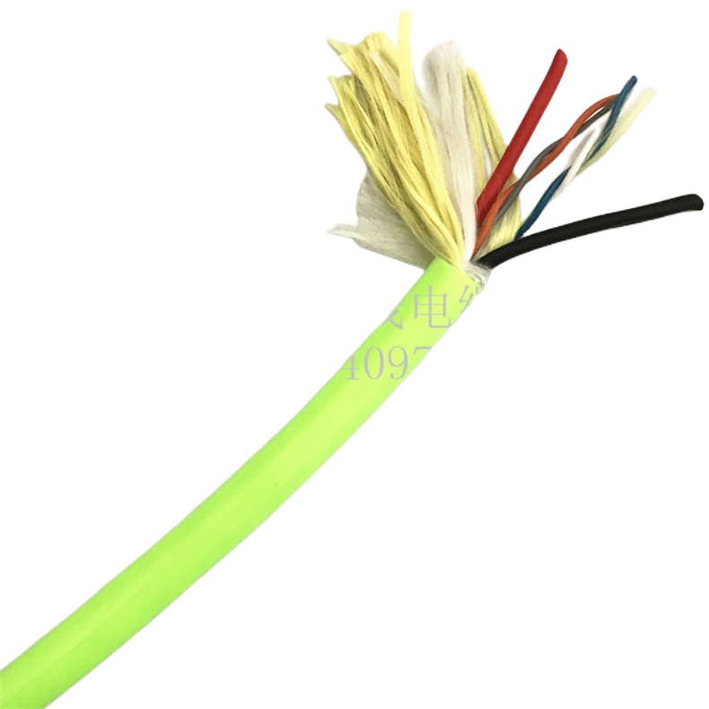
RST-RB Series Product Matrix
PUR flexible control cable for robotics — standard and encoder variants
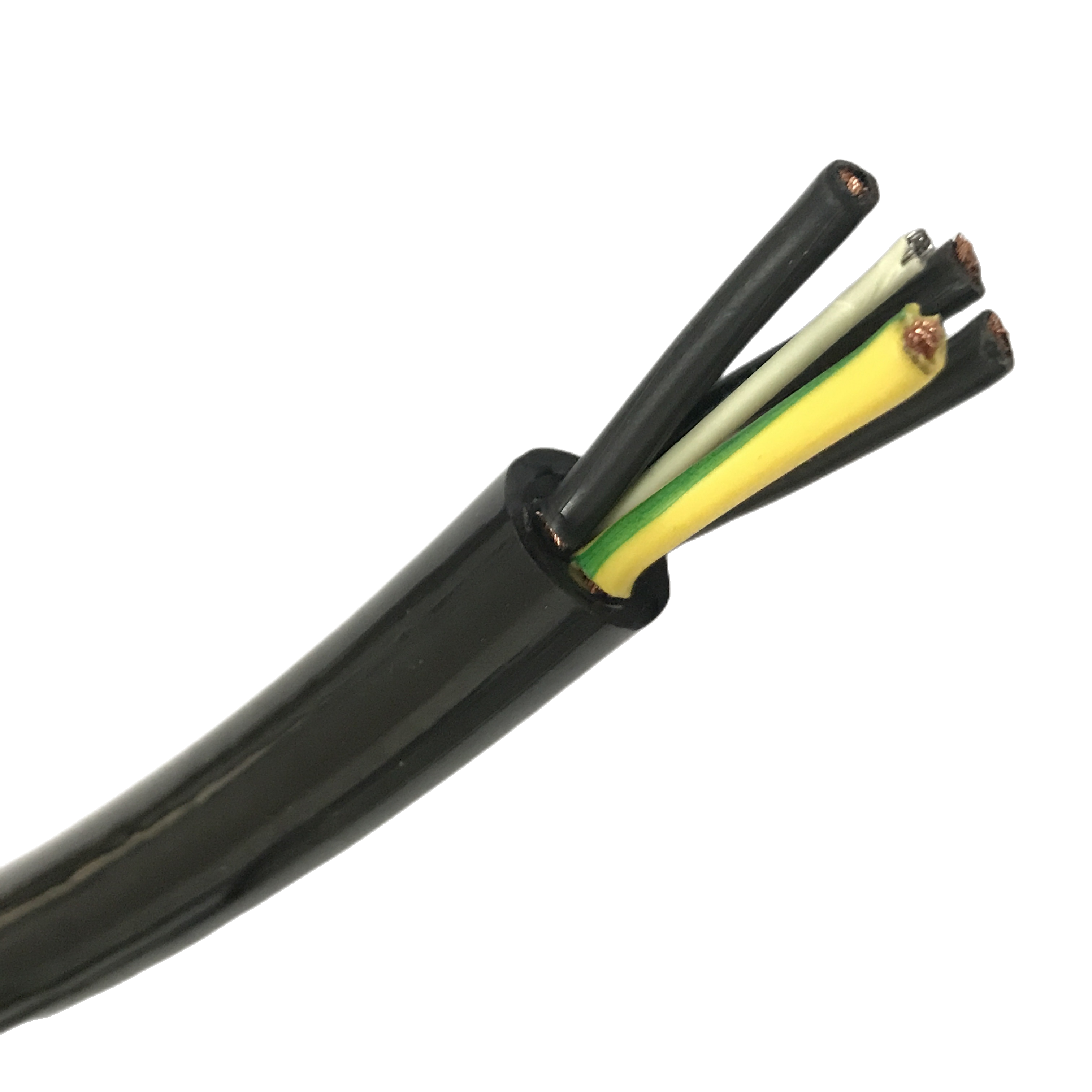
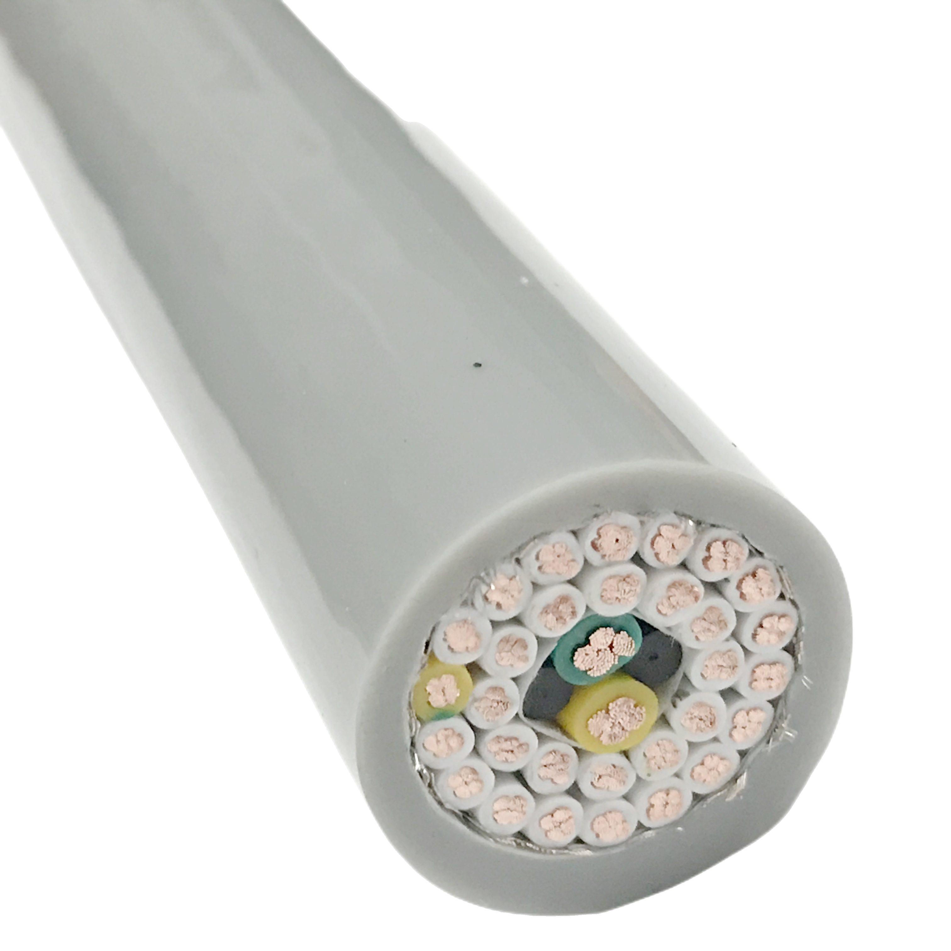
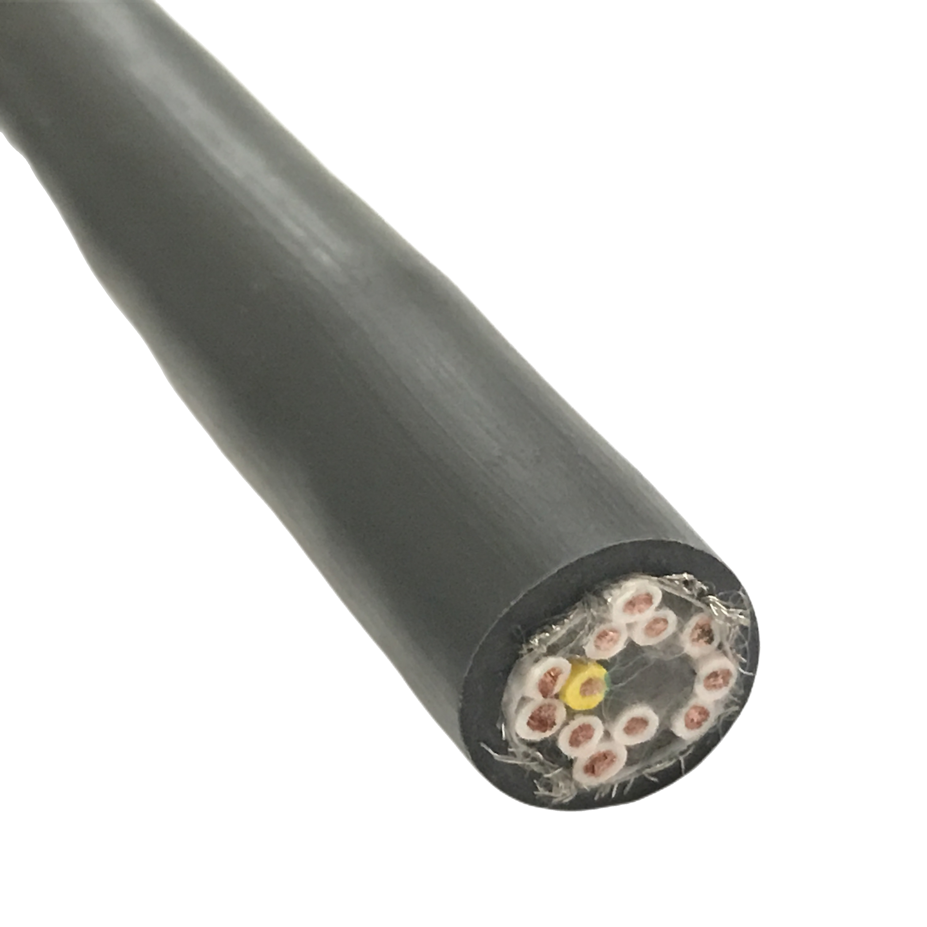
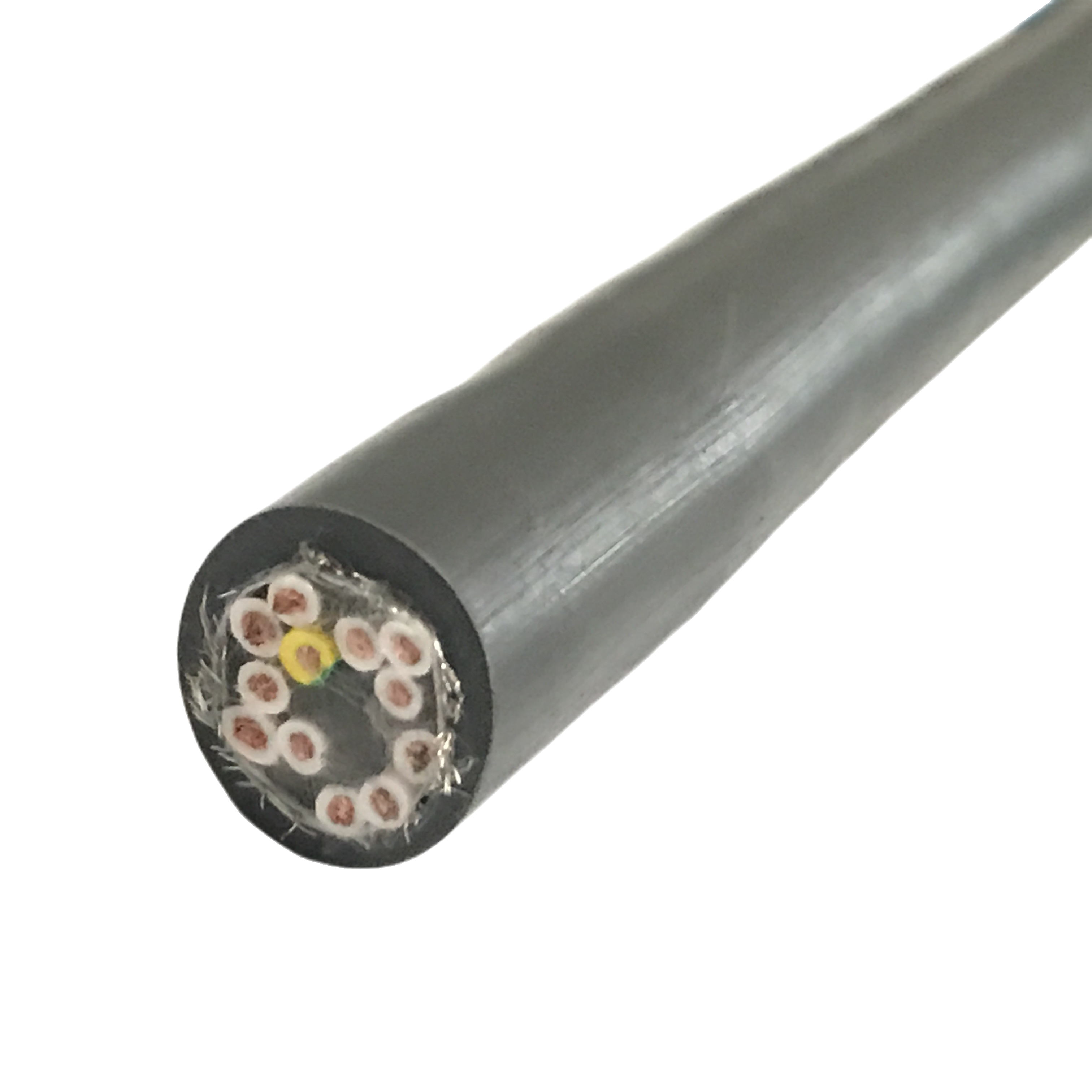
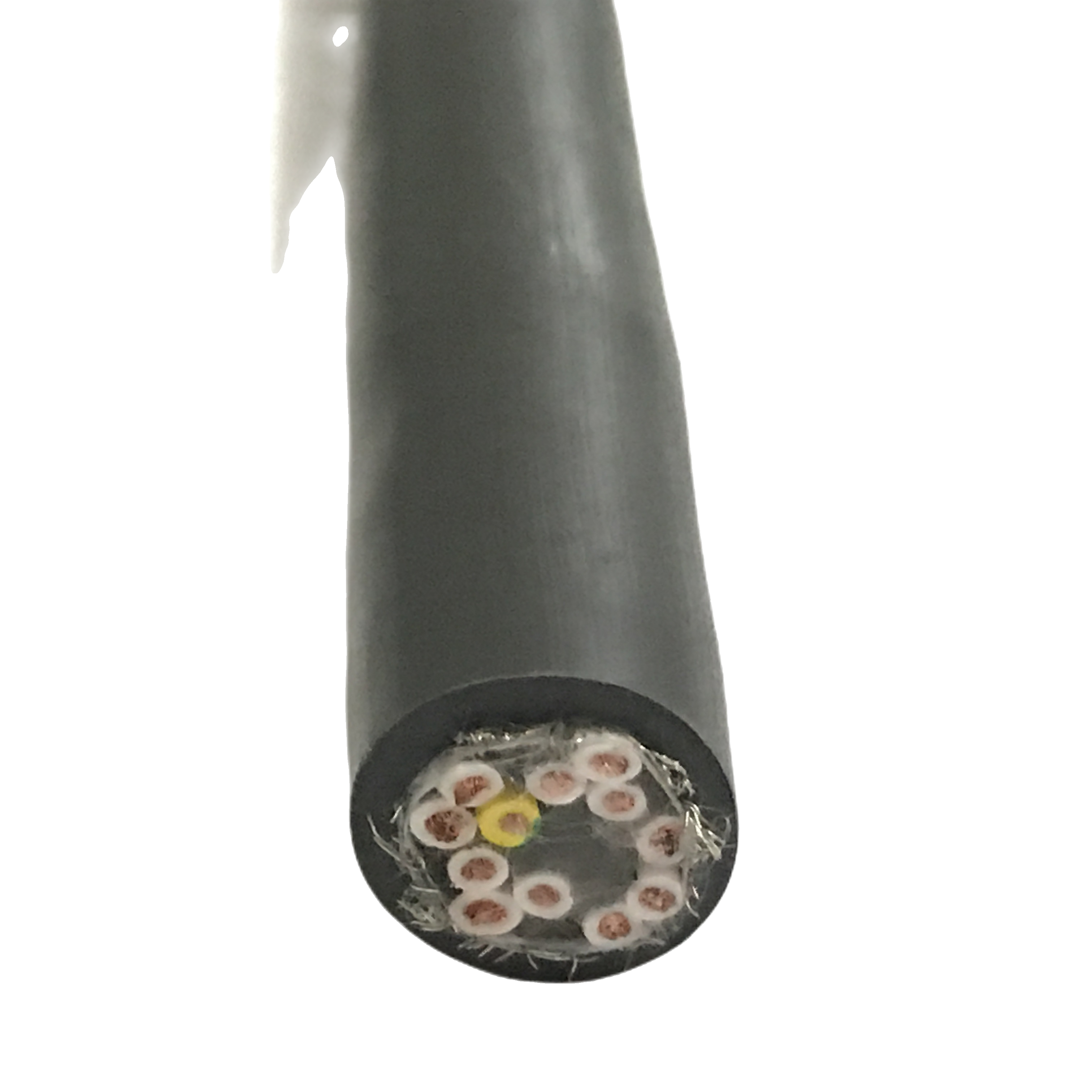
Eleven standard configurations. All models: IEC 60228 Class 6 helical-lay OFC conductors, foamed TPE filler, 35° braid weave angle (shielded models), ether-type PUR 88 Shore A jacket. ETO variants available for traverse speeds above 5 m/s, torsion above ±180°/m, and clean-room LSZH jacket.
|
Model |
Cores × mm² |
Shield |
Flex life |
Torsion |
OD (mm) |
Temp °C |
Application |
|
RST-RB-110 |
4 × 0.34 mm² |
None |
≥5M |
±180°/m |
5.5±0.3 |
−40/+90 |
J6 / signal-only |
|
RST-RB-120 |
4 × 0.75 mm² |
None |
≥5M |
±180°/m |
7.0±0.3 |
−40/+90 |
J2–J4 control |
|
RST-RB-130 |
7 × 0.75 mm² |
None |
≥5M |
±180°/m |
9.2±0.3 |
−40/+90 |
Lower arm I/O |
|
RST-RB-210 |
4 × 0.34 mm² |
Cu braid overall |
≥5M |
±180°/m |
7.0±0.3 |
−40/+90 |
EMC signal / servo env. |
|
RST-RB-220 |
4 × 0.75 mm² |
Cu braid overall |
≥5M |
±180°/m |
8.8±0.3 |
−40/+90 |
J4/J5 wrist (primary) |
|
RST-RB-230 |
12 × 0.75 mm² |
Cu braid overall |
≥5M |
±180°/m |
13.2±0.4 |
−40/+90 |
Full I/O + EMC |
|
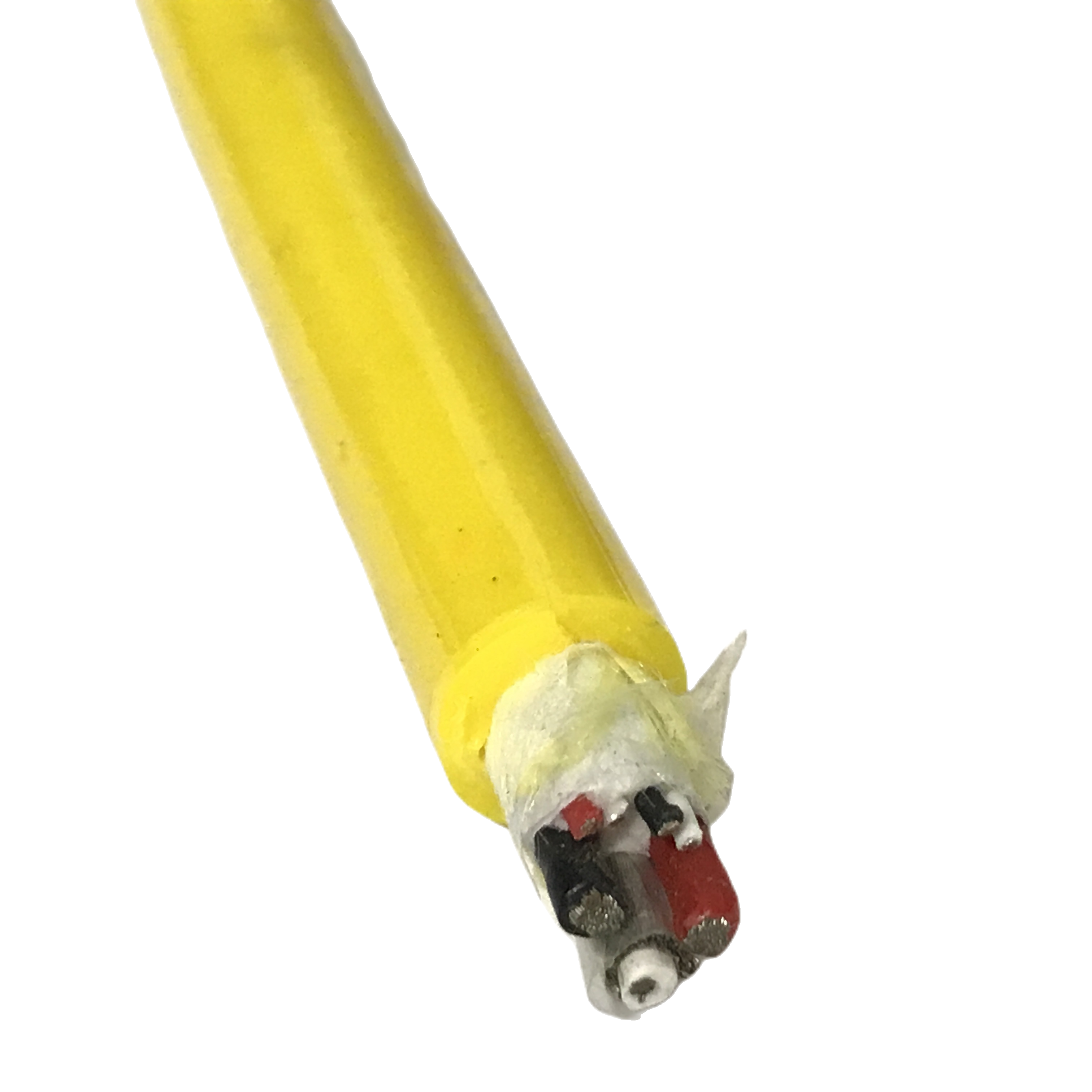
RST-RB-310 |
2 pr × 0.14 mm² |
Pair foil + braid |
≥5M |
±180°/m |
6.2±0.3 |
−40/+90 |
Encoder / resolver |
|
RST-RB-320 |
4 pr × 0.25 mm² |
Pair foil + braid |
≥5M |
±180°/m |
8.5±0.3 |
−40/+90 |
Servo feedback |
|
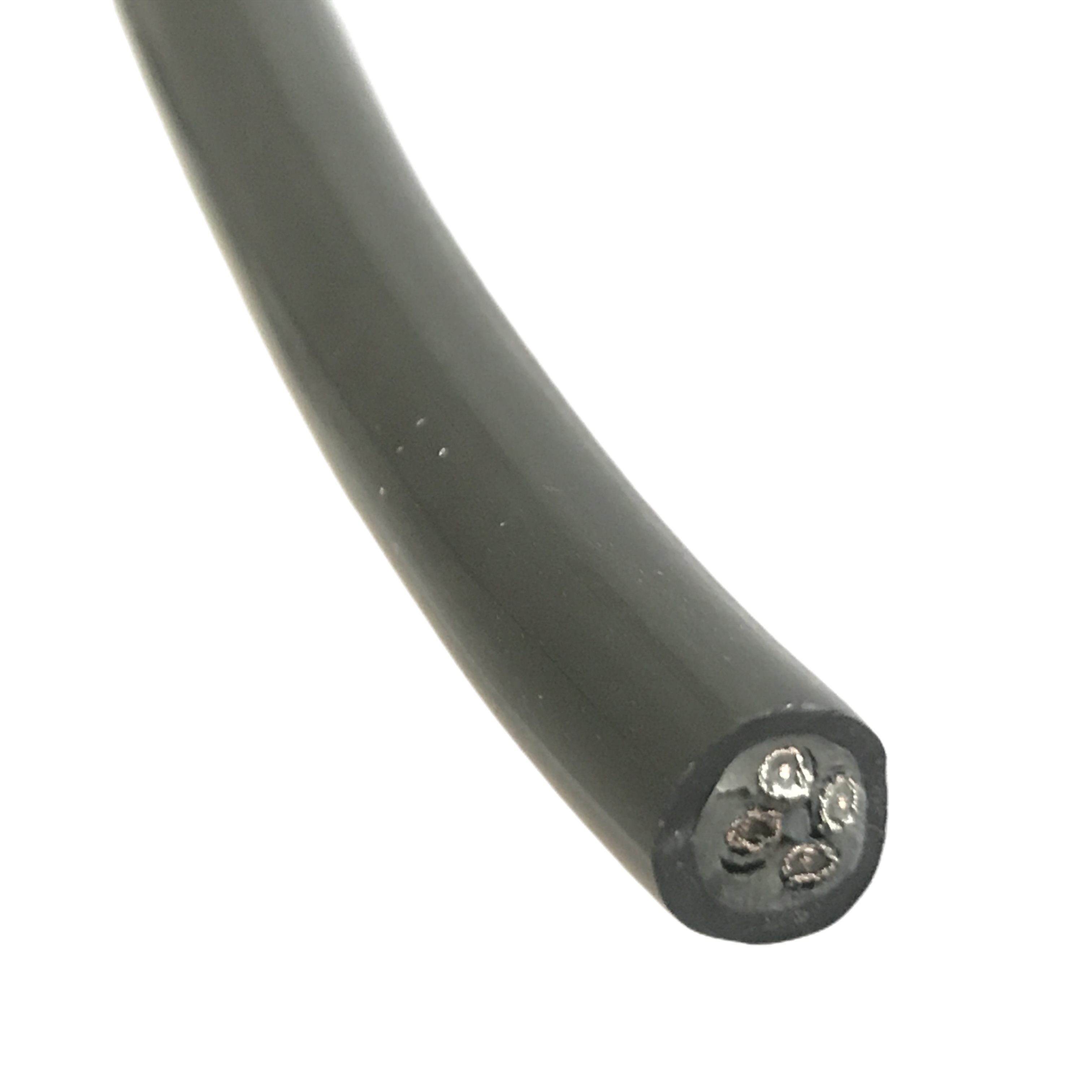
RST-RB-410 |
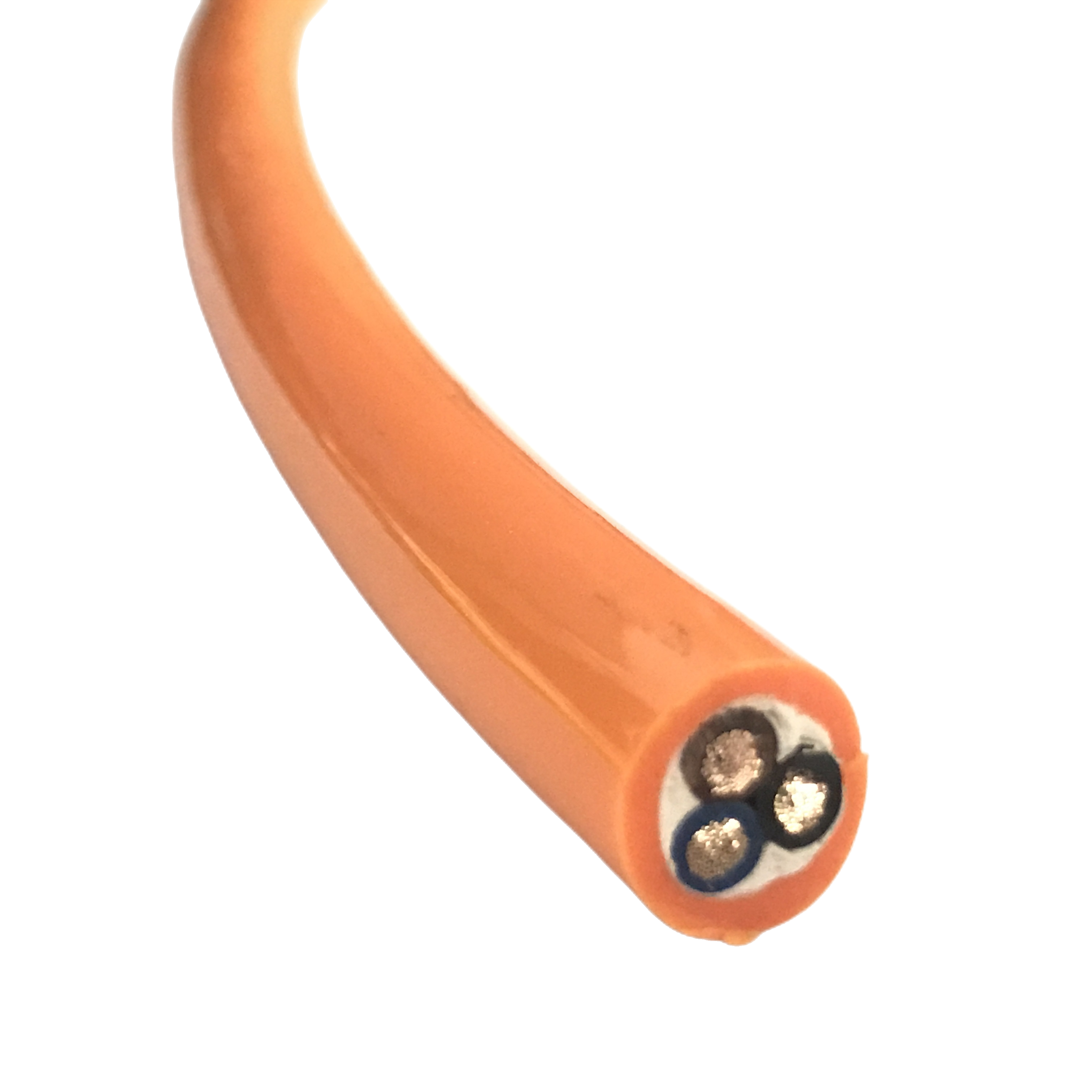
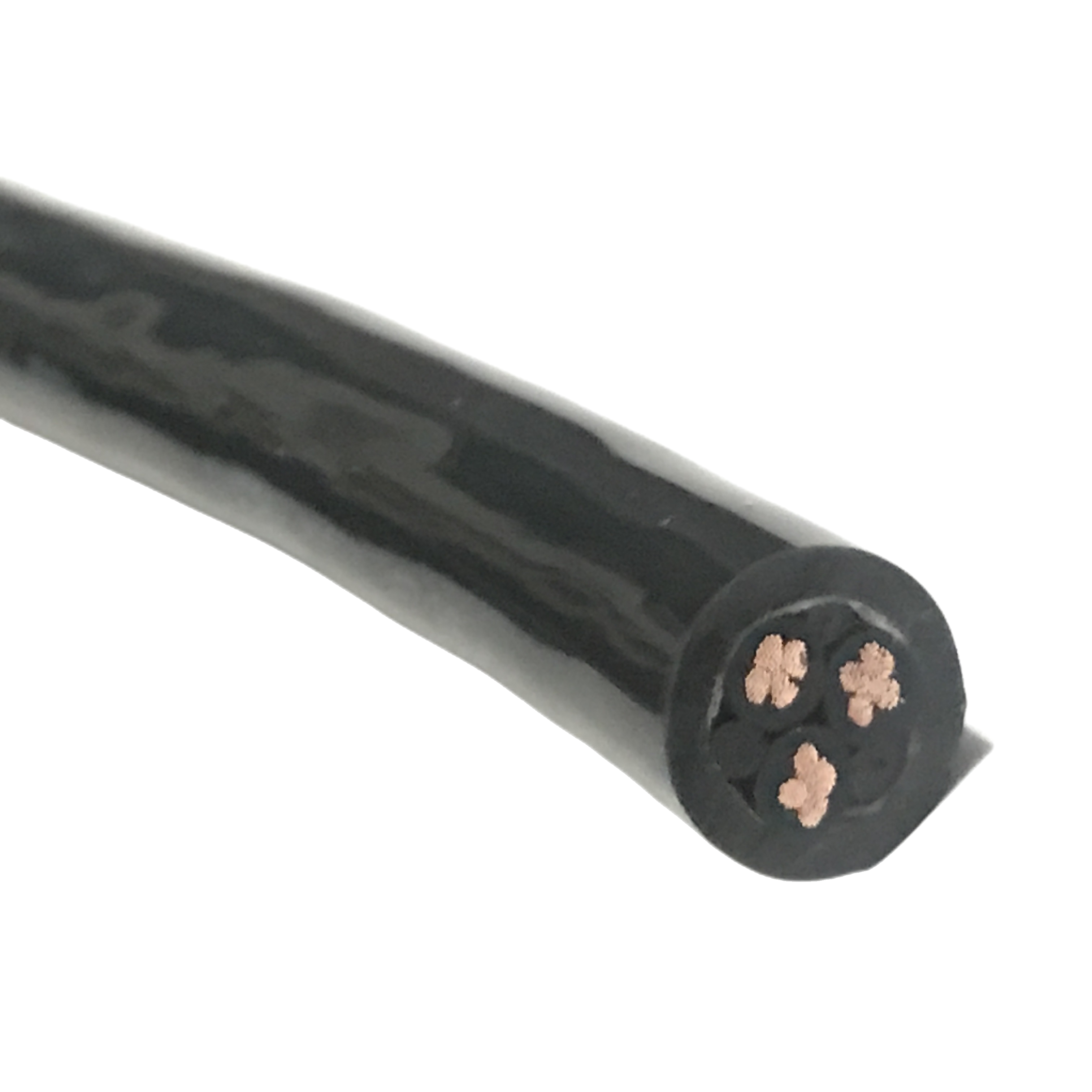
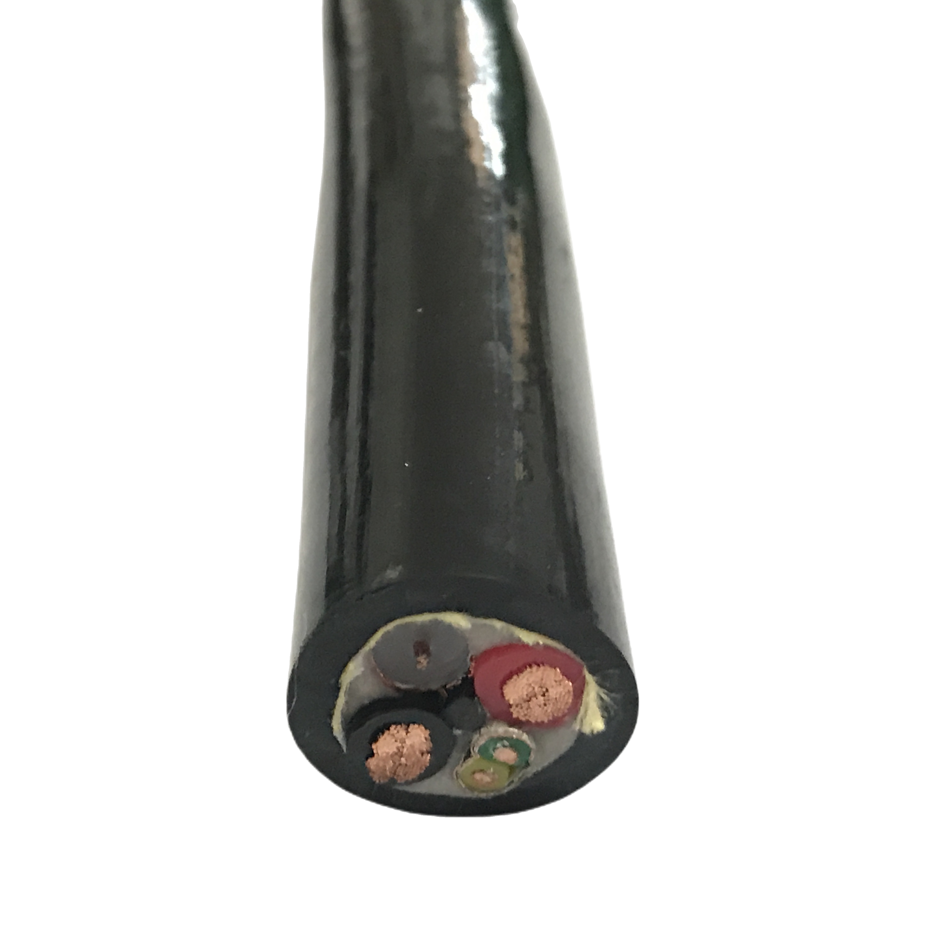
3 × 1.5 mm² |
None |
≥3M |
±90°/m |
10.0±0.4 |
−40/+90 |
Servo motor power |
|
RST-RB-420 |
3×1.5+4×0.75 |
Cu braid overall |
≥3M |
±90°/m |
14.5±0.5 |
−40/+90 |
Combined pwr + ctrl |
|
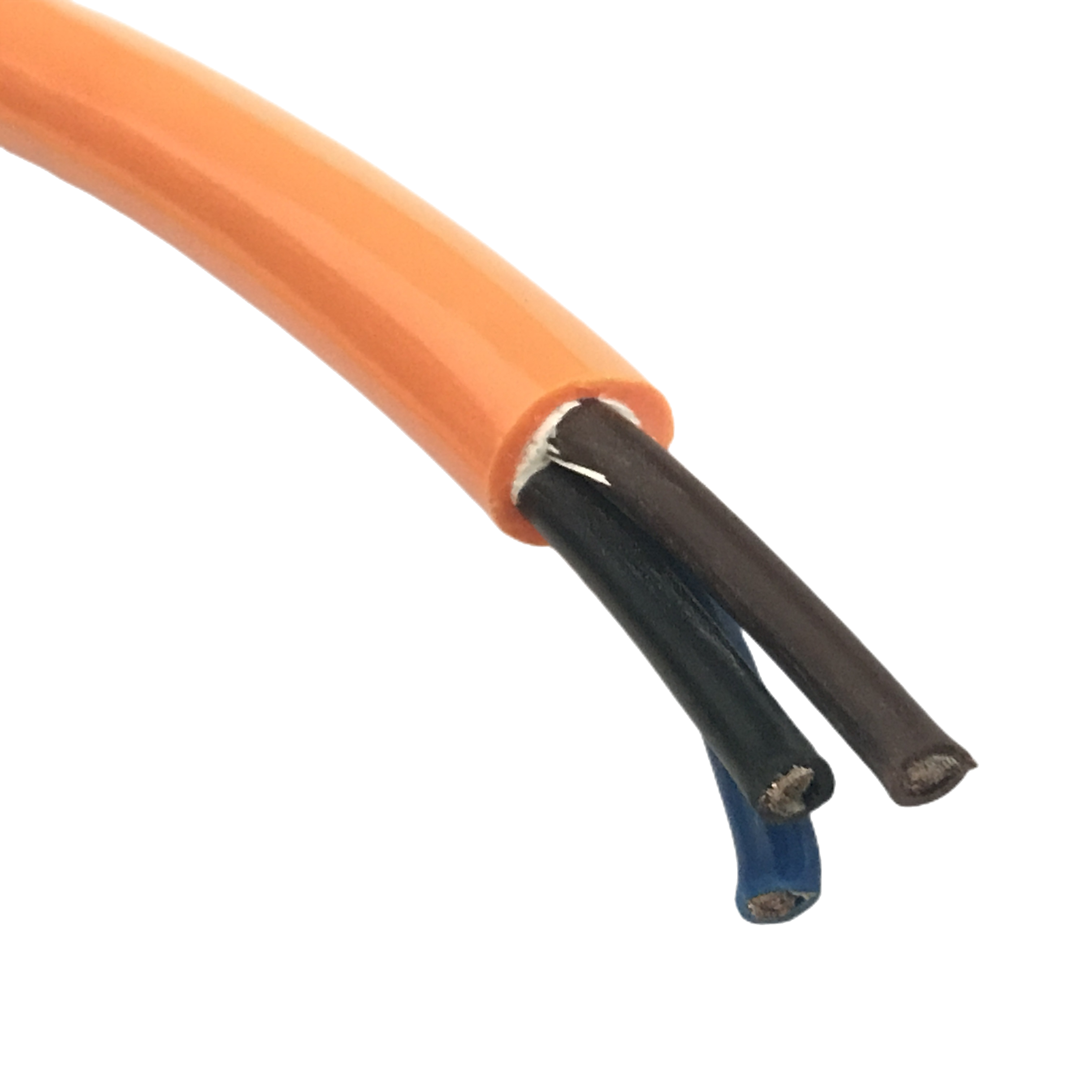
RST-RB-500 (cobot) |
4 × 0.75 mm² |
Cu braid overall |
≥5M |
±180°/m |
8.8±0.2 |
−40/+90 |
ISO/TS 15066 cobot |
|
RST-RB-C (ETO) |
Per spec |
Per spec |
Per design |
Up to ±270°/m |
4–25 mm |
Per jacket |
PUR/TPE/LSZH |
RST-RB-500 cobot model note: OD tolerance tightened to ±0.2 mm (standard models ±0.3–0.5 mm). Consistent OD is required for calibrated collision detection algorithms in ISO/TS 15066 collaborative robot installations where the end-effector or cable mass is part of the collision force calculation. Outer jacket edge profile is radiused (no sharp seams) per cobot safety enclosure requirements. See dedicated cobot section below.
Complete Technical Specification
Conductor and helical lay parameters
|
Parameter |
Specification |
|
Standard |
IEC 60228 Class 6 — ultra-fine stranding; wire count: 0.34 mm²: ≥130; 0.75 mm²: ≥196; 1.5 mm²: ≥280; 0.14 mm² (encoder): ≥100 |
|
Individual wire diameter |
≤ 0.10 mm (signal/control); ≤ 0.09 mm (encoder pairs); ≤ 0.12 mm (1.5 mm² power). Below the copper endurance limit at 5× OD bend radius under combined multi-axis loading |
|
Lay type and angle |
Helical lay; 15–20° lay angle per OD; reversal between concentric layers. Provides elastic torsion compliance — cable returns to natural position after torsion load release. Cannot be replaced by straight-lay cable at the same rated torsion angle |
|
Torsion rating (signal/control) |
±180°/m of free cable length — continuous bi-directional. Not a single-direction wind-up limit. Power models (RST-RB-4xx): ±90°/m due to 1.5 mm² conductor stiffness |
|
Conductor material |
Oxygen-free copper (OFC) per ASTM B170 standard; silver-coated OFC available for encoder models RST-RB-310/320 — silver maintains stable contact resistance at connector terminals through 5M cycles |
|
DC resistance @ 20°C |
0.34 mm²: ≤56.0 Ω/km · 0.75 mm²: ≤25.5 Ω/km · 1.5 mm²: ≤13.7 Ω/km · 0.14 mm²: ≤131 Ω/km |
Filler, insulation, and core assembly
|
Parameter |
Specification |
|
Core filler compound |
Foamed TPE elastomer, 45–55 Shore A; compresses under diagonal torsional load and recovers fully on release. Cross-section ovality after 5M multi-axis cycles: ≤ 2.8% (rigid PE equivalent: ≥ 14% — 5× worse) |
|
Serve layer |
Polyester textile serve between core assembly and outer jacket; allows the core bundle to rotate ±5° relative to the jacket under torsion — prevents jacket from transmitting torsion stress directly to conductors |
|
Insulation compound |
Semi-rigid PVC (standard, 300/500 V); XLPE (oil-immersion and high-temp, 90°C rated, 450/750 V); LSZH (clean-room/semiconductor ETO, halogen-free IEC 60754-1) |
|
Core stranding sequence |
Concentric layers; inner layer lay factor 8–10×; outer layer 10–12×; reverse lay direction between layers. Balanced lay prevents net torque accumulation under continuous bi-directional rotation |
|
Voltage rating |
Signal/control: 300/500 V AC. Power (RST-RB-4xx): 450/750 V AC. Withstand test: 2,000 V AC / 1 min per production lot |
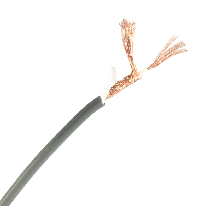
Shielding performance through multi-axis cycling
The shielding data below was measured on RST-RB-220 (4 × 0.75 mm², overall braid shield) on Rousheng’s multi-axis test rig at the stated cycle checkpoints. Measurement method: transfer impedance per IEC 62153-4-3.
|
Cycle checkpoint |
TI @ 1 MHz (mΩ/m) |
TI @ 10 MHz (mΩ/m) |
Optical coverage (%) |
Assessment |
|
0 (as manufactured) |
38 |
62 |
86% |
Pass |
|
500,000 cycles |
41 |
65 |
84% |
Pass |
|
1,000,000 cycles |
48 |
71 |
83% |
Pass |
|
3,000,000 cycles |
61 |
84 |
82% |
Pass |
|
5,000,000 cycles |
74 |
96 |
82% |
Pass (< 100 mΩ/m limit) |
PUR jacket — oil resistance and mechanical parameters
RST-RB uses ether-type PUR at 88 Shore A. The choice of ether versus ester type is the most consequential material decision in the cable — with the wrong chemistry, the jacket appears intact at 12 months and fails catastrophically at 15–18 months due to autocatalytic hydrolysis.
|
Parameter |
Specification |
|
Compound type |
Ether-type PUR, 88 Shore A. Ether linkages are not hydrolysis-susceptible — no degradation in environments with RH > 60% or temperature > 40°C. Ester-type PUR undergoes autocatalytic degradation in these conditions |
|
Oil — Group 1 (IRM 902 mineral oil) |
IEC 60811-2-1 Group 1; 7-day immersion at 70°C: tensile retention ≥ 80%; elongation retention ≥ 75%. Suitable for hydraulic oil, gear oil, machine lubricant |
|
Oil — Group 2 (IRM 903 cutting fluid) |
IEC 60811-2-1 Group 2; 7-day immersion at 70°C: tensile retention ≥ 70%. Suitable for water-soluble cutting fluids at ≤ 70°C. Not suitable for undiluted neat cutting oil above 70°C |
|
Abrasion resistance |
Taber CS-10 / 500 g: 18 mg / 1,000 cycles. Slightly higher than RST-DC drag chain grade (15 mg at 92 Shore A) — the 4-point hardness reduction for elastic recovery trades 20% abrasion mass loss increase, which is acceptable because robot cable abrasion contact is intermittent, not continuous |
|
Permanent set — multi-axis cycling |
Jacket diameter change after 5M multi-axis cycles: ≤ 3.0%. PVC jacket under equivalent test: 12–18% permanent deformation — causes binding in robot arm conduits within 300,000–500,000 cycles |
|
Temperature |
−40°C to +90°C continuous; cold flex −40°C no cracking at 5× OD (IEC 60811-1-4); short-term +105°C (15 min). Ether-type PUR maintains elasticity throughout without plasticiser migration |
|
Chemical resistance |
Resistant: mineral oil, hydraulic fluid, water-soluble coolant, IPA, dilute alkali (pH ≤ 10), dilute acid (pH ≥ 4). Not resistant: toluene, xylene, concentrated ketones, MEK |
Free Cable Length Calculation: Symmetric and Asymmetric Axes
How to calculate free length for any PUR control cable robot axis
The free cable length at each robot joint must be sufficient to keep the torsional loading within the cable’s ±180°/m rating. An undersized free length does not cause immediate failure — it causes silent permanent twist accumulation that shortens cable life by a factor of 3–5× compared to a correctly routed installation.
Step 1 — Determine total rotation angle
The total rotation angle is the sum of the positive and negative range of motion at that joint — not double the single-direction value, and not the peak single-direction angle. For a symmetric axis (J6: ±360°): total = 360° + 360° = 720°. For an asymmetric axis (J1: +200°, −150°): total = 200° + 150° = 350°.
The asymmetric case is the most common source of free-length calculation errors. Engineers unfamiliar with the formula sometimes use 2 × the larger single-direction angle (2 × 200° = 400° for the J1 example), which overestimates the required free length by 14% and wastes installation space, or use only the larger single-direction angle (200°), which underestimates by 43% and causes premature failure.
Step 2 — Apply the free length formula
Free length (m) = total rotation (°) ÷ 180 × 1.20
The 1.20 factor is a 20% installation margin that accounts for routing geometry (cable never travels in a perfectly straight line between attachment points) and temperature effects (PUR stiffness increases at low temperature, requiring slightly more free length at −40°C than at +23°C).
Worked examples for common robot configurations
|
Axis |
Positive range |
Negative range |
Total rotation |
Free length calculation |
Minimum free length |
|
J1 base rotation |
+210° |
−150° |
360° |
360 ÷ 180 × 1.20 |
2.40 m |
|
J2 lower arm |
+145° |
−75° |
220° |
220 ÷ 180 × 1.20 |
1.47 m |
|
J4/J5 wrist |
+180° |
−180° |
360° |
360 ÷ 180 × 1.20 |
2.40 m |
|
J6 tool rotation |
+360° |
−360° |
720° |
720 ÷ 180 × 1.20 |
4.80 m |
|
Cobot J6 (limited) |
+270° |
−270° |
540° |
540 ÷ 180 × 1.20 |
3.60 m |
|
ETO cable (±270°/m) |
+360° |
−360° |
720° |
720 ÷ 270 × 1.20 |
3.20 m (saves 1.6 m) |
|
ASYMMETRIC AXIS NOTE |
When a robot axis has different positive and negative ranges (e.g. J1: +210°, −150°), always use the sum of both absolute values as the total rotation angle (360° in this case), not 2 × the larger value (420°) and not the single-direction maximum (210°). The RST-RB-C ETO model at ±270°/m torsion rating reduces required free length by 33% compared to the standard ±180°/m models — useful when routing space is constrained at J6 or J1. |
Collaborative Robot (Cobot) Cable Requirements
Why standard PUR flexible control cable is not sufficient for ISO/TS 15066 cobot applications
Collaborative robots operating under ISO/TS 15066 power-and-force-limiting mode use the cable — its mass and outer profile — as inputs to the collision force calculation that triggers the safety stop. A cable whose outer diameter varies by ±0.5 mm between reels, or whose outer surface has a seam, ridge, or unpredictable geometry, introduces error into the collision model that causes either false stops (too sensitive) or under-sensitivity (safety gap).
Standard RST-RB models have an OD tolerance of ±0.3–0.5 mm — acceptable for industrial robots where the cable is fully enclosed in an arm conduit. RST-RB-500 is produced with tightened OD tolerance (±0.2 mm) and a radiused outer jacket profile, specifically for cobot tool-changer tether and end-effector mounting applications where the cable is exposed in the collaborative workspace.
RST-RB-500 cobot variant — specific requirements and parameters
|
Parameter |
RST-RB-500 specification |
|
OD tolerance |
±0.2 mm (standard models ±0.3–0.5 mm). Tight tolerance required for ISO/TS 15066 collision mass calculation consistency. Batch-to-batch OD certified on dimensional inspection report |
|
Outer surface geometry |
Circumferentially uniform profile; no extruder seam or surface ridge. Seam-free surface prevents collision-point force concentration that triggers false safety stops on sensitive force-torque sensors |
|
Edge profile at connector |
Radiused overmold at both ends; no sharp edges or projections within the collaborative workspace zone. Per ISO/TS 15066 Table A.2 (contact location and force limits) |
|
Cycle rate profile |
Cobot duty cycle differs from industrial robot: lower traverse speed (typically 0.25–1.5 m/s) but higher cycles per shift (200–600 per 8-hour shift vs 80–150 for industrial). 5M cycle rating at cobot operating speed is validated at 1 m/s with ±180°/m torsion |
|
Mass per metre (for collision model) |
RST-RB-500 (4 × 0.75 mm², shielded): 95 ± 3 g/m. Certified on delivery note for ISO/TS 15066 payload and collision calculation inputs. Different core counts change mass — confirm at order |
|
Colour (outer jacket) |
Standard: RAL 7035 light grey (robot-arm standard). Optional: RAL 9003 signal white, RAL 5015 sky blue. Custom RAL available ETO. Colour does not affect electrical or mechanical specification |
|
Documentation |
OD certification report, mass per metre certificate, and surface geometry inspection report included with each shipment. Available for inclusion in cobot system CE technical file under Machinery Directive 2006/42/EC |
Joint-by-Joint Selection Guide
PUR control cable selection mapped to each robot axis
The loading combination at each joint determines which RST-RB model and which installation parameter to prioritise. The guide below covers the six standard 6-axis robot joints plus cobot and linear-motor axes.
|
Axis |
Recommended model |
Selection reasoning and critical parameter |
|
J1 — base rotation |
RST-RB-120 / 220 |
J1 carries the highest cumulative torsion angle. Total rotation is typically 300–400°; free length requirement 2.0–2.7 m. Shielded model (RST-RB-220) required if the base cable run passes through the same cable duct as servo drive cables. |
|
J2/J3 — lower arm |
RST-RB-130 / 230 |
Lower arm joints flex primarily in one plane with < ±30°/m torsion in most installations. 7-core and 12-core configurations cover all lower-arm I/O without a second cable. Shielded model where servo drive cables are co-routed. |
|
J4/J5 — upper arm and wrist |
RST-RB-220 (shielded, mandatory) |
J4 and J5 impose the most severe combined loading: near-full flex plus near-full torsion simultaneously at high duty cycle. Shielding is mandatory at this location — J4/J5 are adjacent to the servo motor, the highest EMI source on the arm. Free length: verify ≥ total J4 + J5 combined rotation ÷ 180 × 1.20 m (joints may compound). |
|
J6 — tool centre rotation |
RST-RB-110 or RST-RB-310 (encoder) |
J6 typically carries only tool power, I/O signal, and encoder feedback — small core count, compact OD priority. For ±360° J6 rotation: free length ≥ 4.80 m. Where routing cannot accommodate 4.80 m, specify RST-RB-C ETO at ±270°/m — required free length drops to 3.20 m. RST-RB-310 required if end effector has resolver or absolute multi-turn encoder. |
|
Cobot tool changer |
RST-RB-500 |
OD tolerance ±0.2 mm for collision model consistency. Seam-free outer surface. Mass certified at 95 ± 3 g/m (4 × 0.75 mm² shielded). See dedicated cobot section above for full ISO/TS 15066 parameter set. |
|
Linear motor axis |
RST-RB-C ETO (high-speed) |
Standard RST-RB rated to 5 m/s traverse. Semiconductor and gantry linear axes above 5 m/s require ETO with bonded TPE filler (prevents core migration at centrifugal acceleration > 50 m/s²). Specify traverse speed, stroke length, and peak acceleration in enquiry. |
Oil and Chemical Resistance: Environment-Specific Selection
Matching PUR flexible cable jacket to the robot workcell environment
Oil degradation in robot cable jackets occurs through two independent mechanisms. Understanding which mechanism is active in a given environment determines the correct jacket specification.
Mechanism 1 — Surface attack (detected within weeks)
Surface attack is measurable by IEC 60811-2-1 immersion testing — tensile strength and elongation at break are measured before and after immersion. Group 1 fluids (mineral oil, hydraulic fluid) cause < 20% tensile loss in ether-type PUR after 7-day immersion at 70°C. Group 2 fluids (water-soluble cutting coolant) cause < 30% tensile loss. Both remain within the cable’s operating margin.
Mechanism 2 — Plasticiser extraction (detected at 6–18 months)
PVC insulation contains plasticisers (DEHP or equivalent) that migrate from the insulation into surrounding oil over 6–18 months. The insulation gradually hardens and becomes brittle. This mechanism is invisible to standard oil immersion testing — the insulation passes the 7-day test but fails in service at 12 months. XLPE insulation contains no plasticiser and is not susceptible to this mechanism.
RST-RB standard models use PVC insulation — adequate for splash and intermittent oil contact. Specify XLPE insulation (RST-RB-C ETO) for continuous immersion applications.
Environment-to-specification decision table
|
Workcell environment |
Fluid type |
Active degradation mechanism |
RST-RB specification |
|
Automotive weld shop |
Hydraulic oil, grease, weld spatter |
Surface attack (Group 1): ether-type PUR handles this. Weld spatter: adds thermal shock — use heat-shrink protection sleeves at J4/J5 |
RST-RB-220 standard PUR; protection sleeve at weld proximity sections |
|
CNC machine tool |
Water-soluble cutting fluid (Group 2) |
Surface attack (Group 2): tensile retention ≥ 70%. Insulation plasticiser extraction in continuous immersion at > 50°C |
Standard RST-RB for splash only. XLPE insulation ETO for continuous immersion or > 50°C coolant temperature |
|
Food processing |
Alkaline detergents, steam, food-grade lubricants |
Alkaline attack at pH > 10 (some aggressive CIP agents). Steam cycles > 100°C degrade standard PVC insulation within 6 months |
RST-RB-C ETO: FDA 21 CFR 177.2600 jacket compound; XLPE insulation; confirm cleaning agent pH and temperature at order |
|
Semiconductor clean room |
IPA, DI water; photoresist solvents (MEK, PGMEA) in some areas |
Photoresist solvents attack both PUR and standard PVC. IPA and DI water: no degradation at room temperature |
RST-RB-C ETO with LSZH jacket (IEC 60754-1 halogen-free); XLPE insulation; no PUR — confirm solvent type at order |
|
General machining / assembly |
Mineral oil splash, no immersion |
Surface attack only; exposure is intermittent. Ether-type PUR 88A handles routine splash with no degradation |
Standard RST-RB (any model); no ETO required |
Field Diagnostic Reference: Robot Cable Failure Patterns
Diagnosing PUR flexible cable failures at robot joints — measurable thresholds
Five failure patterns account for the large majority of robot cable faults reported to Rousheng’s application engineering team. The detection method column lists the specific instrument and measurement needed to confirm the root cause before cable replacement.
|
Symptom |
Root cause |
Detection method |
Threshold |
Correction |
|
Encoder dropout at specific joint angle, not random |
Braid breakage at wrist — wrong braid weave angle for torsion |
TI measurement at 1 MHz (IEC 62153-4-3) at the suspect joint angle |
TI > 100 mΩ/m = braid failure; < 80 mΩ/m = wiring fault elsewhere |
Replace with RST-RB-220 (35° weave angle). Verify free length meets rotation ÷ 180 × 1.20. Check conduit entry angle ≤ 15°. |
|
Cable permanently twisted — does not return to straight |
Torsion exceeded ±180°/m — helical lay wound past elastic limit |
Lay pitch calliper measurement on straight-laid section vs specification |
Lay pitch deviation > 15% = permanent distortion |
Recalculate free length using correct asymmetric axis formula. If routing cannot provide required free length, order RST-RB-C ETO at ±270°/m — reduces required length 33%. |
|
Jacket splits longitudinally, surface becomes tacky |
Ester-type PUR hydrolysis — autocatalytic acid degradation in humid or wet environment |
pH test on surface condensate or cleaning fluid in cable area |
If condensate pH < 5.5, hydrolysis acid is present; confirms ester-type PUR |
Replace with RST-RB ether-type PUR — no hydrolysis susceptibility. When sourcing from other suppliers: require written confirmation of PUR chemistry type (ether vs ester). |
|
Open circuit at J6 connector — intermittent at tool rotation extremes |
No service loop at end effector — conductor work-hardening at terminal under combined tension + torsion |
Kelvin 4-wire resistance at connector terminal vs mid-cable section; measure at +360° and −360° J6 positions |
Resistance increase > 8% at extreme positions vs centre = terminal fatigue |
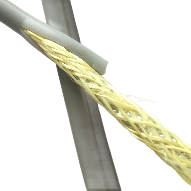
Add ≥ 150 mm service loop. If impossible: ETO cable with Kevlar tensile member (100 N rating) transfers tensile load from conductors to strength member. |
|
Insulation cracks when cable is bent at room temperature |
Plasticiser extraction from PVC insulation into cutting fluid — 6–18 month onset |
Bend cable at 4× OD at 20°C; inspect for micro-cracks with 10× loupe. New cable: no cracking. Deplasticised: cracks at bend outer surface |
Any cracking at 4× OD = insulation replacement required |
Replace with RST-RB-C ETO with XLPE insulation (no plasticiser). For splash-only environments, standard PVC insulation is adequate — specify XLPE for continuous coolant immersion only. |
Frequently Asked Questions
Why does a PUR flexible control cable rated for drag chains fail at robot wrists?
Because the qualification methods measure different things. A drag chain flex life test applies constant-amplitude single-axis bending. A robot wrist applies simultaneous bending, torsion, and axial extension in continuously varying proportions. The fatigue accumulation models are incompatible. A cable that reaches 10,000,000 cycles in a drag chain test may fail in 300,000–500,000 multi-axis cycles if it uses straight conductor lay, rigid PE filler, and standard braid weave geometry — all optimised for single-axis, not multi-axis, loading.
How do I identify ether-type versus ester-type PUR on a cable without a certificate?
You cannot reliably distinguish ether from ester PUR visually or by touch. The only definitive identification method is the polymer chemistry certificate from the jacket compound supplier, referenced on the cable’s material declaration. When sourcing from unfamiliar suppliers, require written confirmation of PUR type in the purchase order acceptance terms. If a jacket develops surface tackiness within 18 months in a humid environment, ester-type hydrolysis is the likely cause — send a jacket sample for FTIR spectroscopy to confirm.
What is the maximum torsion angle that the standard RST-RB series supports?
The standard RST-RB series (all models except RST-RB-4xx power variants) is rated ±180° per metre of free cable length — continuous bi-directional. For a joint requiring ±270°/m, the RST-RB-C ETO variant is available at up to ±270°/m, achieved through a modified lay angle and a different core-to-jacket interface design. Specifying the correct free length at ±180°/m is always preferable to increasing the torsion rating — it is simpler, lower cost, and eliminates the need for ETO lead time.
Can the RST-RB-500 cobot cable be used on standard industrial robots?
Yes, with no performance compromise. The tighter OD tolerance (±0.2 mm) and radiused surface profile of RST-RB-500 do not affect electrical or mechanical performance — they add manufacturing cost. For industrial robot applications where the cable is enclosed in an arm conduit and the OD tolerance does not matter for the application, the standard RST-RB-220 provides identical electrical and flex performance at lower cost. RST-RB-500 is mandatory for cobot applications; it is optional for industrial robots.
What is the minimum order quantity for standard RST-RB models?
Standard RST-RB catalog models (RST-RB-110 through RST-RB-420) and the RST-RB-500 cobot model: minimum 50 m on reel (unterminated) or 10 assembled units with connectors. RST-RB-C ETO designs: minimum 100 m from first production run, with first-article inspection before production release. Sample quantities of 1–5 m are available for application evaluation. The RST-RB-500 cobot model carries a certified documentation package with every shipment — no MOQ surcharge for documentation.
Request Samples, Application Review, or a Quotation
Specifying the right PUR cable for your robot or cobot application
Rousheng provides a free application engineering review — free-length calculation per axis, joint loading confirmation, oil environment assessment, and cobot documentation scope — before order placement. For a complete single-reply technical and commercial response, include:
- Robot make and model, or axis-by-axis range of motion (positive and negative, in degrees)
- Whether any axis is asymmetric (different positive and negative ranges) — most common at J1 and J2
- Core count and cross-section (or list of signals, current ratings, and protocols per axis)
- EMC shielding required: yes/no; if yes, interference source (servo drive, VFD, other)
- Oil environment: fluid type, concentration, contact mode (splash vs immersion), temperature
- Cobot application: yes/no; if yes, ISO/TS 15066 collaboration mode and collision zone classification
- Traverse speed (m/s) and peak acceleration (m/s²) for linear-motor axes
- Required service life in cycles or years at stated cycle rate
- Quantity: metres on reel, or assembled units with connector type at each end
|
CONTACT |
Email: Jerry@rstlkable.com WhatsApp / Phone: +86 134 8219 7396 Address: No. 2591 Fengzhe Road, Fengxian District, Shanghai, China Sample requests: state RST-RB model, cable OD, and joint type (J1–J6 or cobot) for targeted sample selection. |