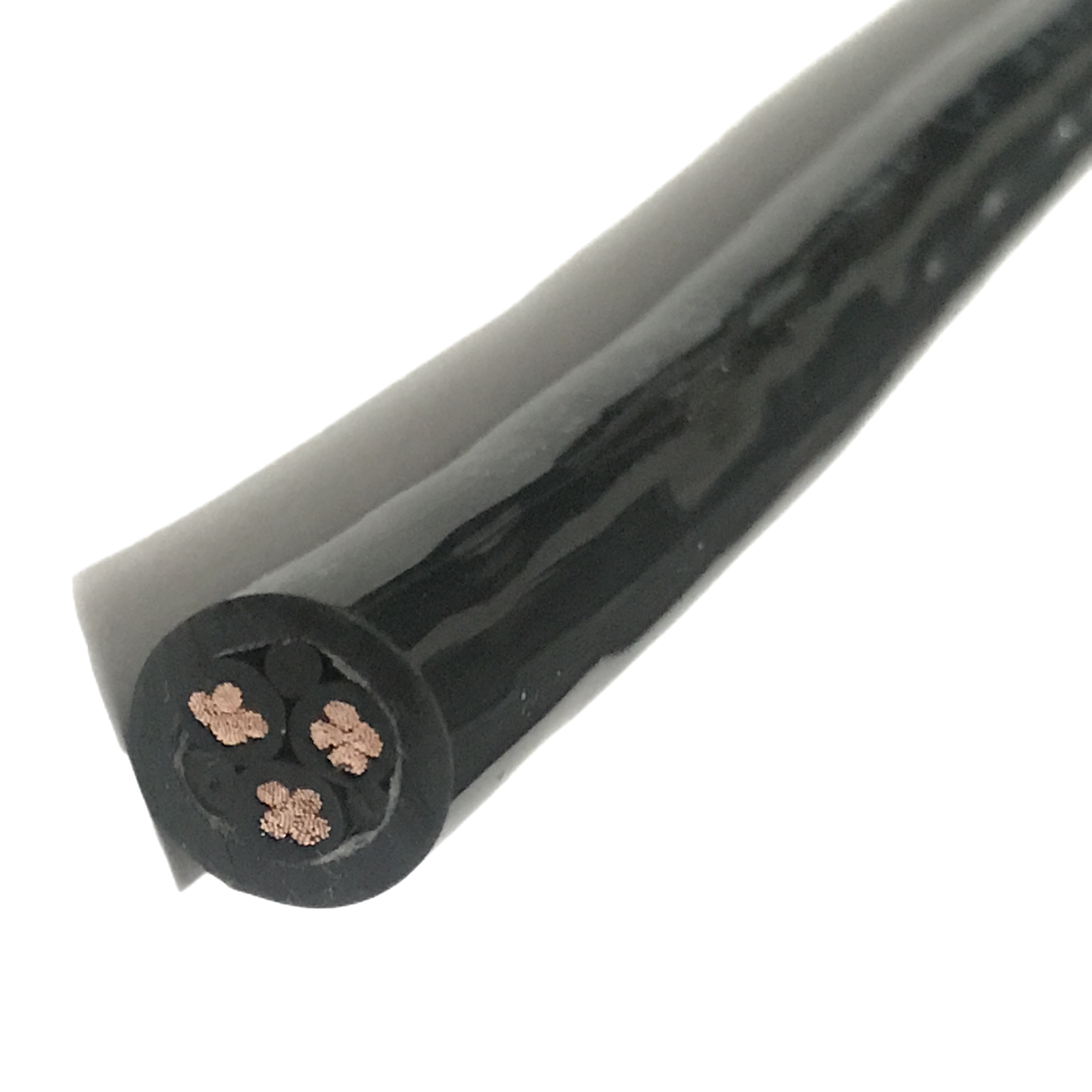
PUR Flexible Control Cable for Drag Chain Applications High Flex Cycles Abrasion Resistant Manufacturer
Designed for continuous motion in drag chain applications, this PUR flexible control cable delivers stable performance under high-cycle bending, abrasion, and mechanical stress.
Key Benefits:
✅ ≥10 million flex cycles for long service life
✅ PUR jacket for superior abrasion and oil resistance
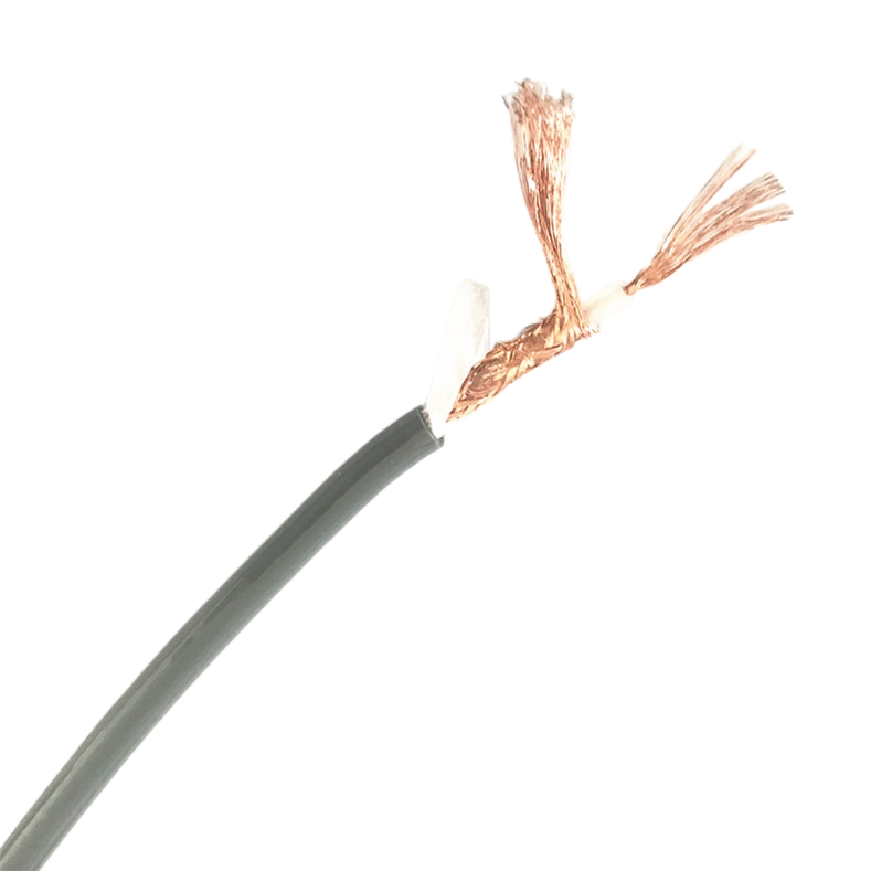
✅ Class 6 ultra-fine conductors for high flexibility
✅ Stable structure prevents deformation and failure
PUR Flexible Control Cable for Drag Chain Applications High Flex Cycles Abrasion Resistant Manufacturer
The PUR flexible control cable is the most-specified cable format for drag chain (energy chain) systems in industrial automation — and also the most frequently misspecified. Choosing the wrong stranding class, the wrong lay length, or the wrong jacket compound for a drag chain installation produces failures that look like mechanical defects but originate in the cable’s construction.
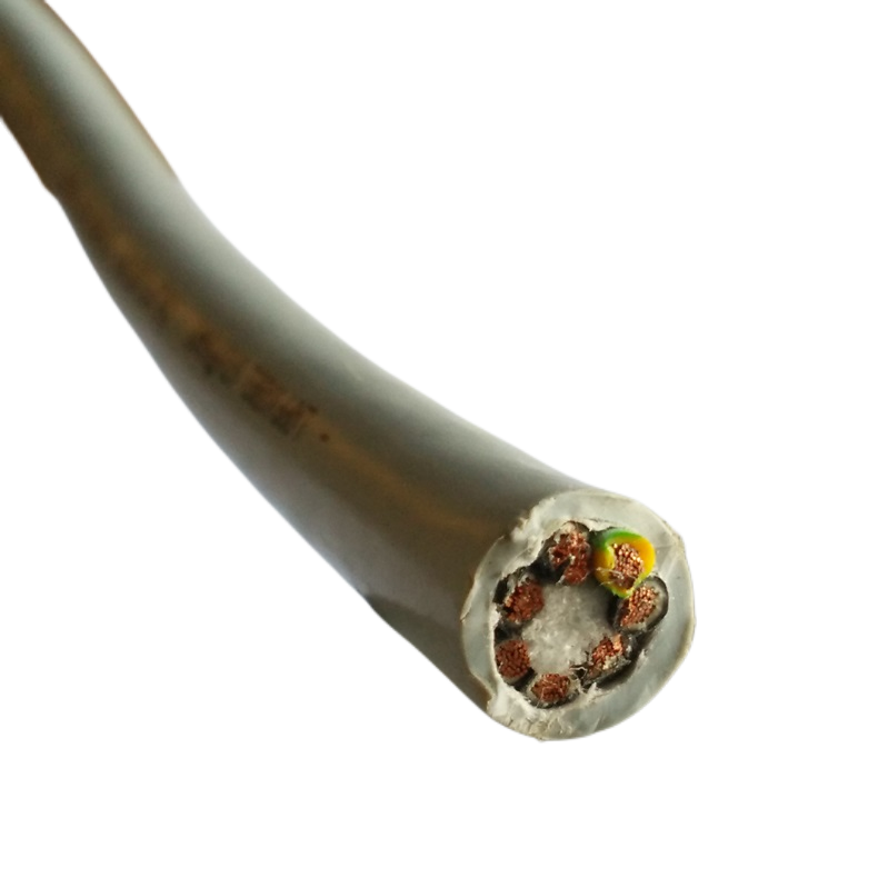
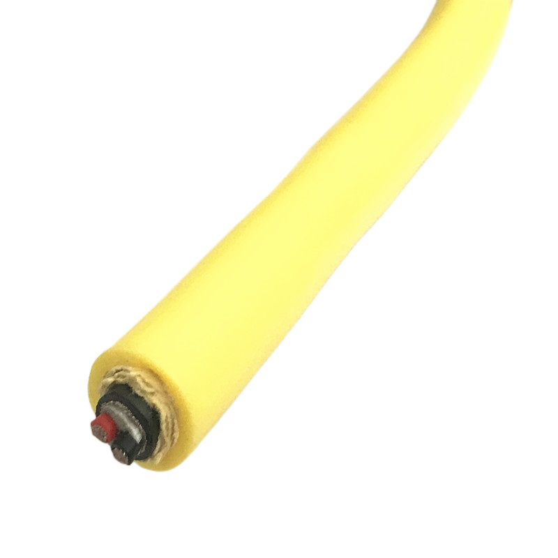
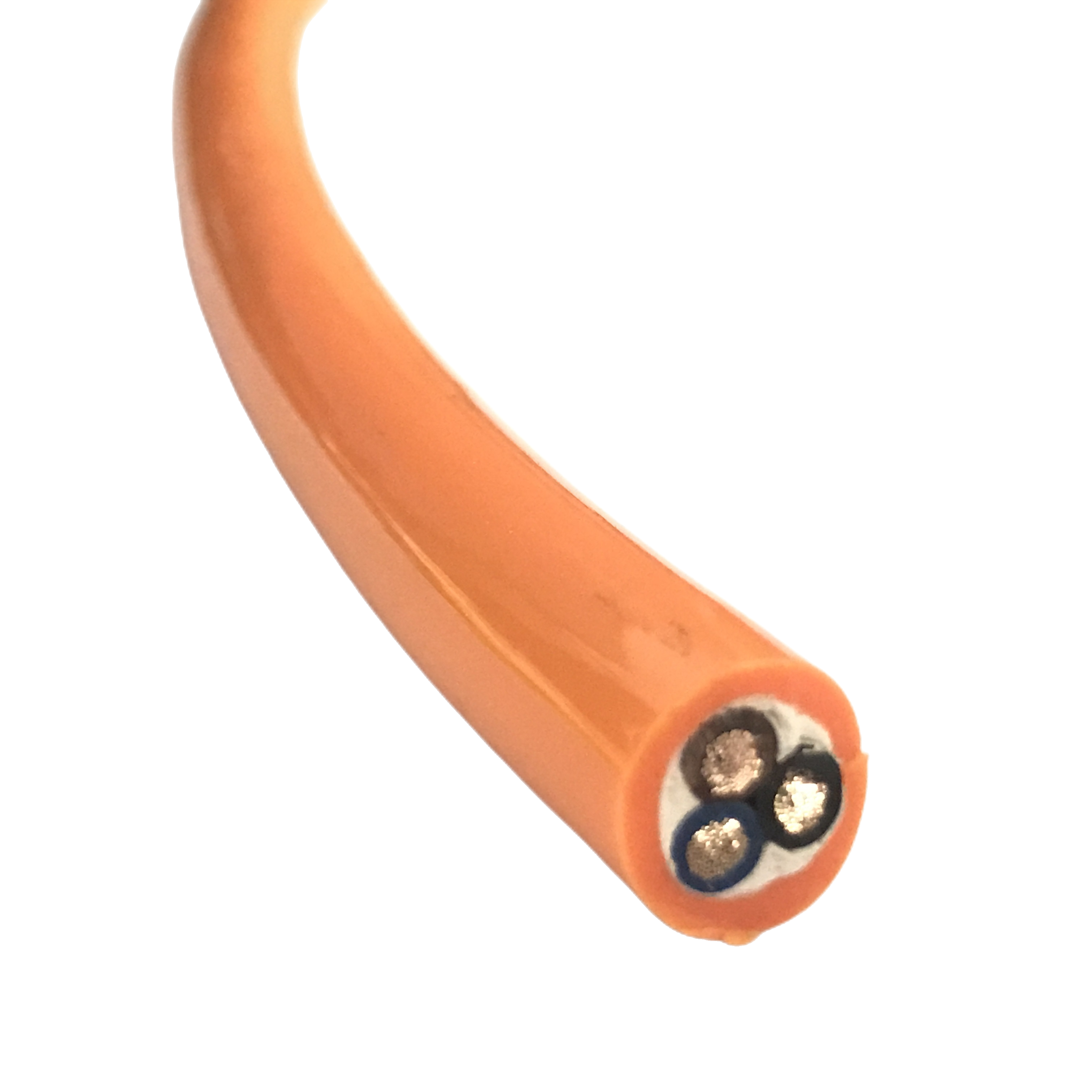
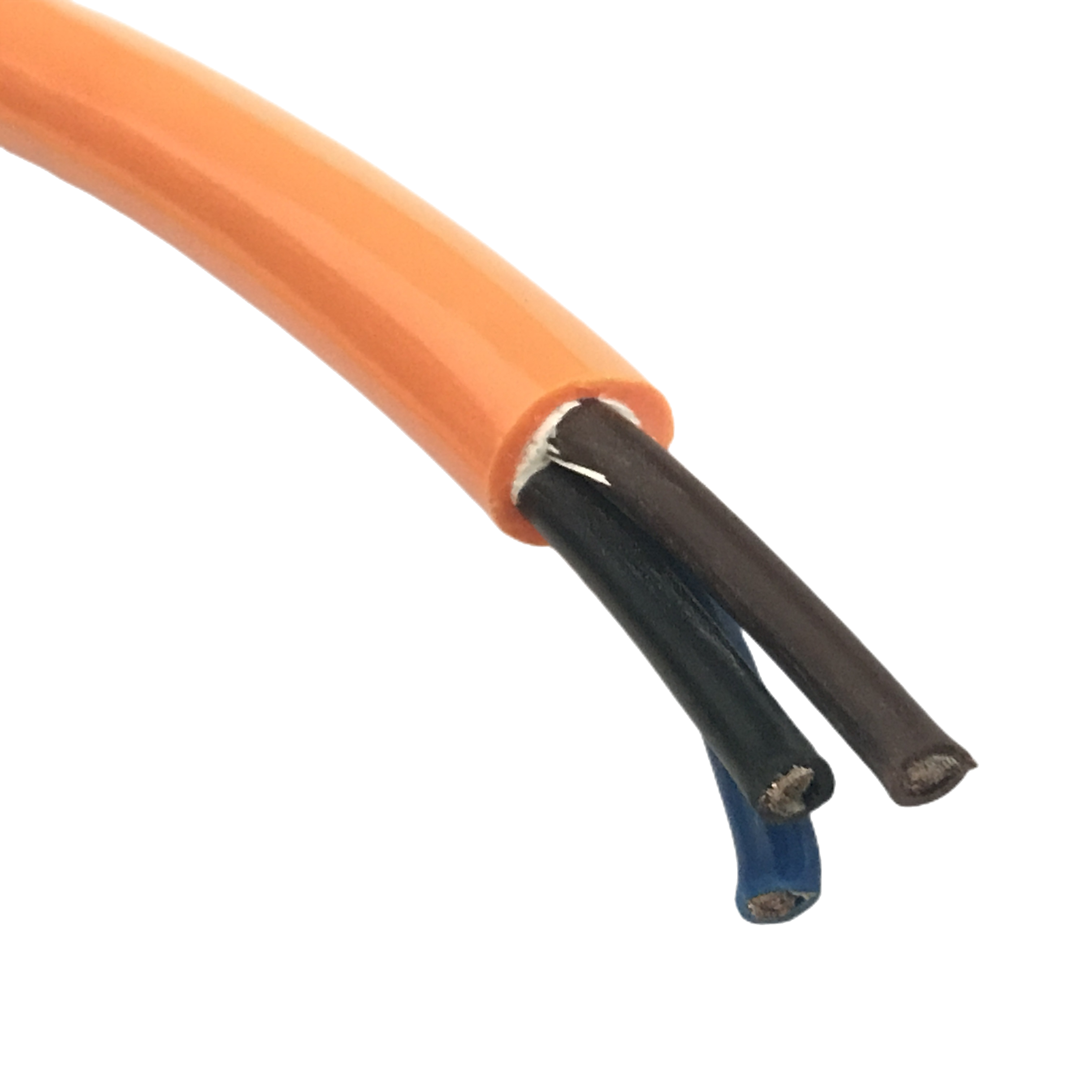
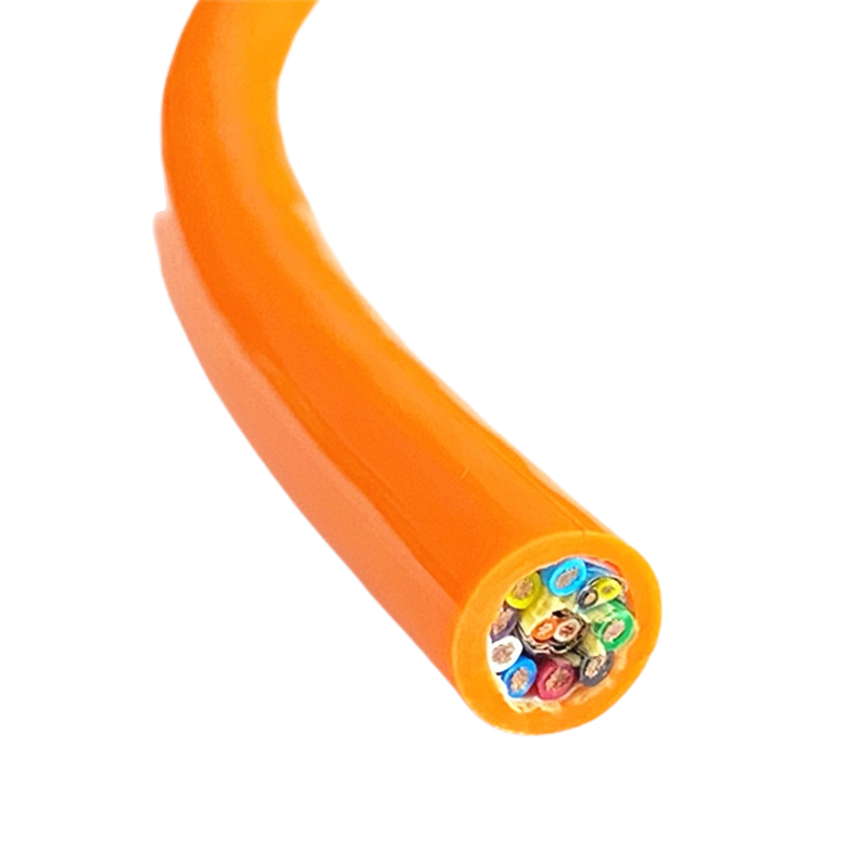
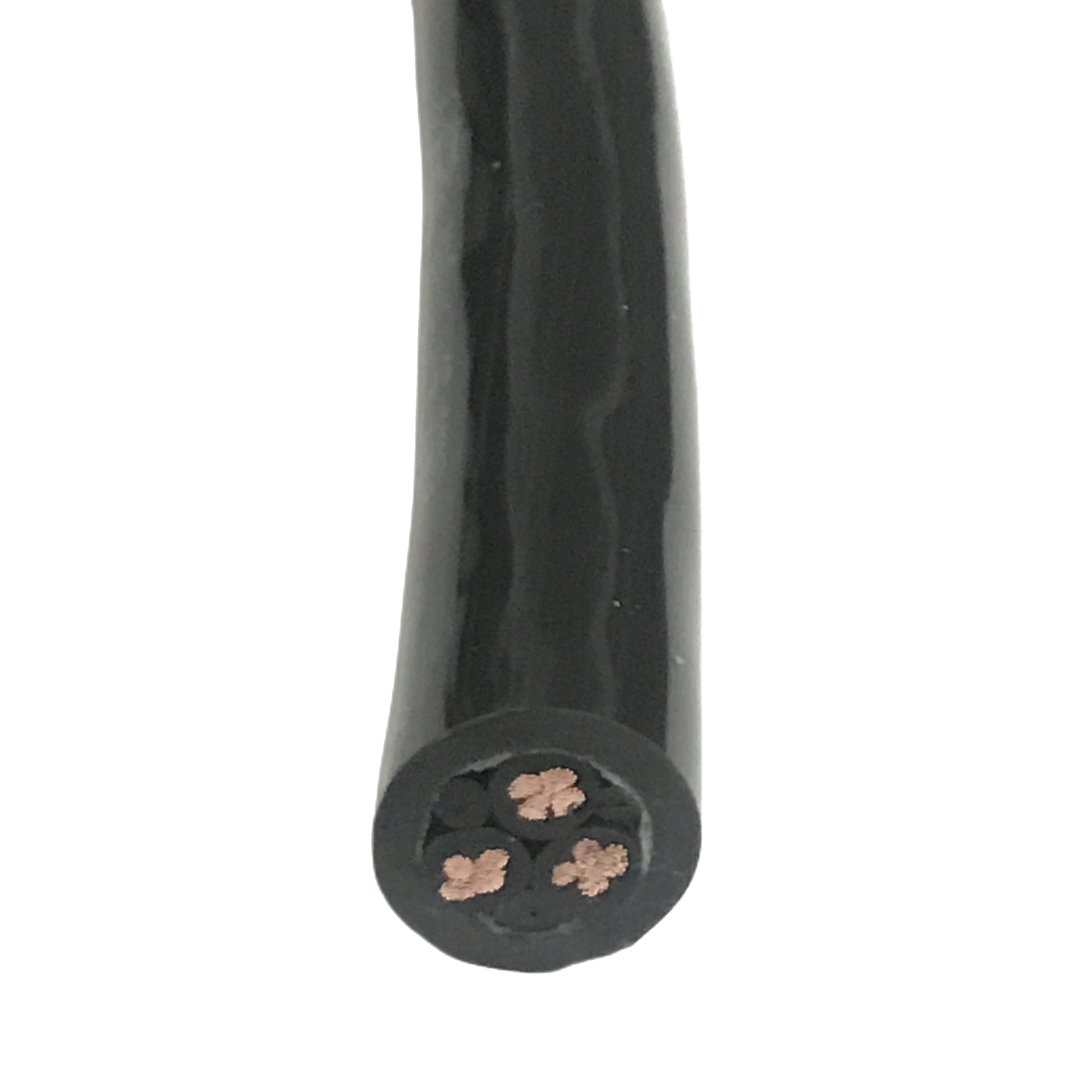
Rousheng’s RST-DC series is engineered specifically for the mechanical demands of continuous-flex drag chain operation: fine-stranded oxygen-free copper conductors, foamed core fillers that maintain circular cross-section under repeated compression, and a polyurethane jacket compound formulated for abrasion resistance rather than simply for UV protection.
This page documents the three failure modes that end drag chain cable life prematurely, the construction parameters that prevent each one, a full product matrix with application-matched variants, and a selection guide that routes you to the correct RST-DC model for your specific machine axis.
|
Flex life |
Jacket compound |
Conductor class |
Temp range |
Standards |
|
≥ 10,000,000 |
PUR 92 Shore A |
IEC 60228 Class 6 |
−40 °C to +90 °C |
UL 21 / CE / RoHS |
|
Cycles at 4× OD bend radius |
Abrasion & oil resistant |
Ultra-fine stranding |
Cold-flex to +90 °C rated |
Halogen-free option |
Three Failure Modes That End Drag Chain Cable Life — and How to Prevent Them
Failure mode 1: conductor work-hardening from incorrect stranding
The most common drag chain cable failure is also the hardest to diagnose in the field: a gradual increase in conductor resistance as fine copper wires work-harden at the bend reversal point. The conductor does not break immediately — it stiffens, loses elasticity, and eventually fractures after 200,000–500,000 cycles.
This failure mode is caused by using IEC 60228 Class 5 conductors — fine-stranded with 16–32 wires per core — in an application that requires Class 6 ultra-fine stranding (≥ 100 wires per core for 0.75 mm²). Class 5 is the standard for flexible cables; it is not adequate for drag chain systems cycling more than 200,000 times per year.
RST-DC conductors use IEC 60228 Class 6 stranding throughout: ≥ 196 wires for 0.75 mm², ≥ 280 wires for 1.5 mm². Individual wire diameter is ≤ 0.10 mm, keeping the bending stress per wire below the copper fatigue limit at 4× cable OD dynamic bend radius.
Failure mode 2: jacket cracking from abrasion contact with chain links
In a drag chain system, the cable lies in the chain trough and contacts the chain link interior surfaces at every direction change. A cable jacket formulated for static installation — standard PVC, for example — abrades through at the chain link contact points within 500,000–1,000,000 cycles depending on chain link geometry and lubrication.
The abrasion failure mechanism is different from UV degradation or chemical attack: it is a surface-wear process driven by repeated sliding contact under compressive load. Jacket hardness, surface texture, and friction coefficient all matter. PVC at 75 Shore A loses surface material rapidly under this condition. PUR at 90–95 Shore A resists the same contact load for 10× longer in direct abrasion tests at equivalent contact pressure.
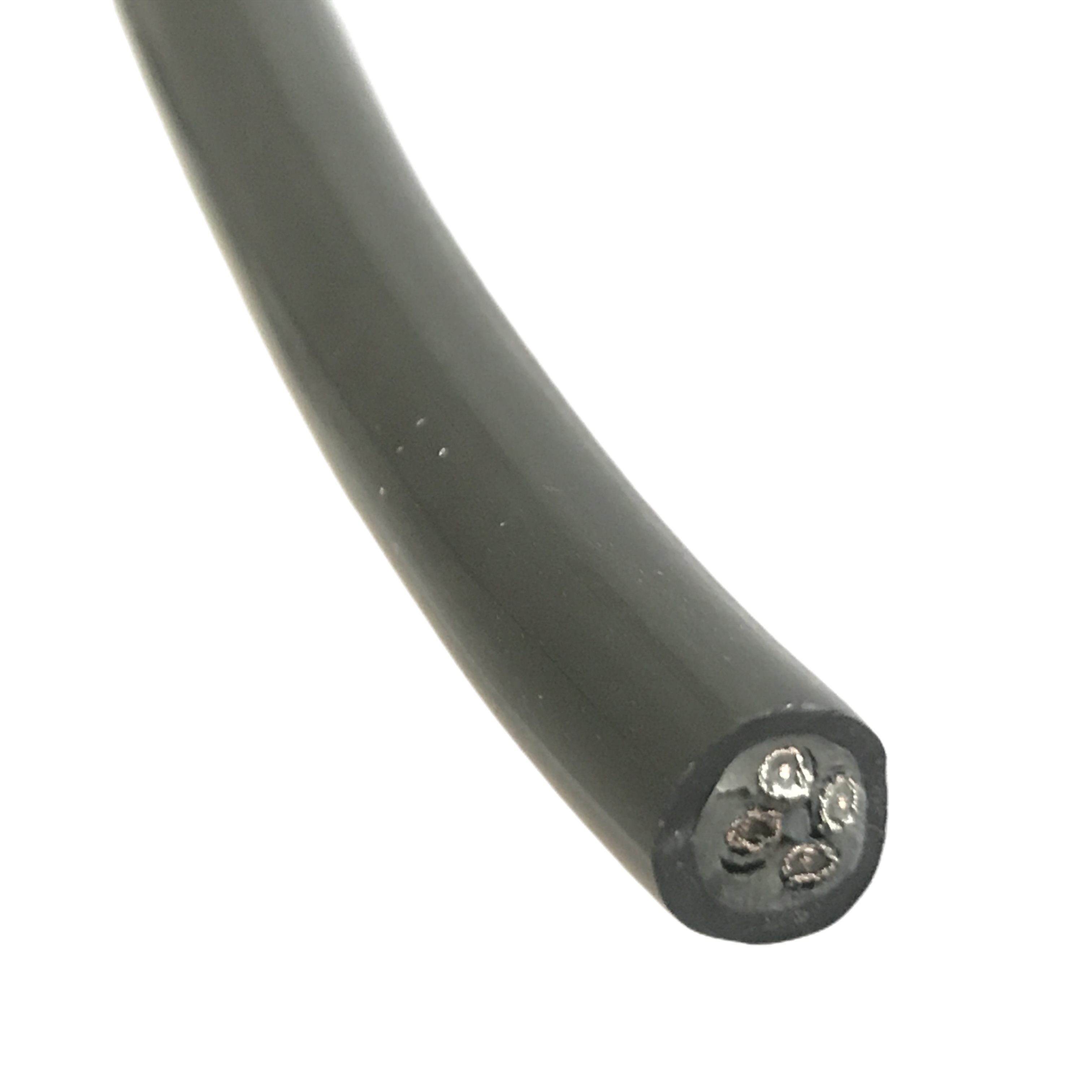
RST-DC jacket compound is formulated at 92 Shore A — hard enough to resist chain link abrasion but soft enough to maintain flexibility at −40 °C without embrittlement. The jacket surface has a defined low-friction texture that reduces stick-slip contact with polished chain link surfaces.
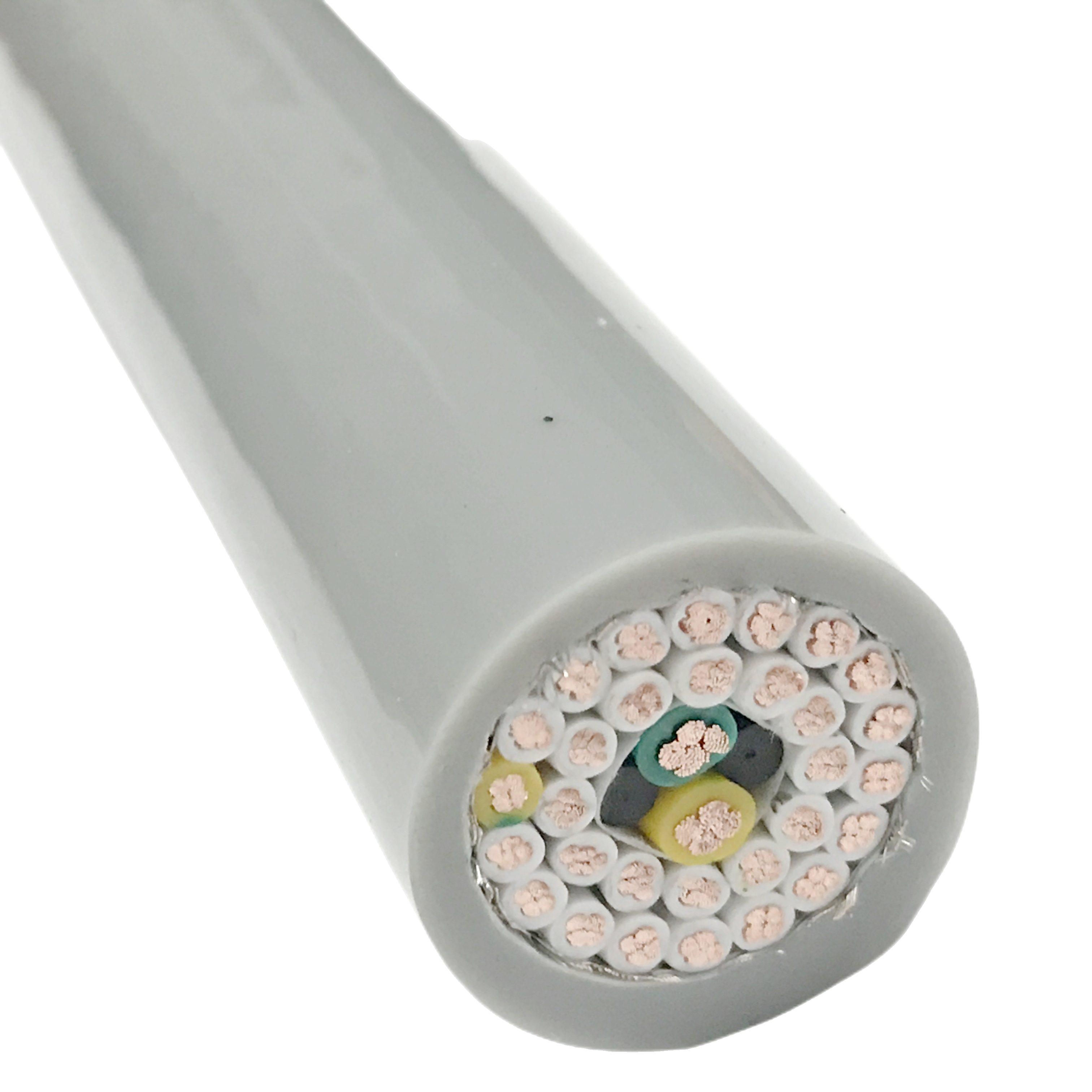
Failure mode 3: cross-section collapse from incorrect core filler design
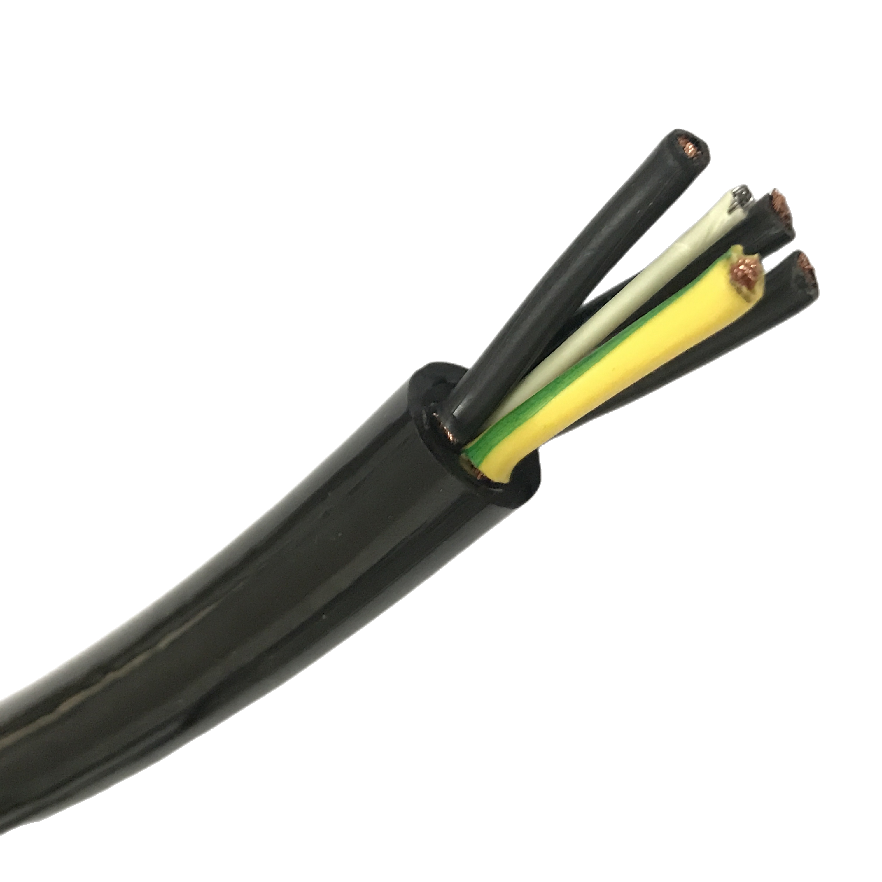
In a multi-core control cable, the spaces between circular conductors must be filled to maintain the cable’s circular cross-section under the compressive loads of drag chain operation. An unfilled or poorly filled cable collapses to an elliptical cross-section when compressed between chain links — the flat geometry causes the outer conductors to travel a longer path on each bend cycle than the inner conductors, producing differential flex fatigue that fractures conductors at the compression face.
RST-DC uses foamed PE filler elements sized and shaped to the specific conductor arrangement of each core count. The filler elements maintain the circular cross-section within ±2% ovality under the compressive loads specified in the DIN EN 60947-5-2 drag chain test standard. This is a designed geometry, not an incidental filling of voids.
|
PRODUCTION NOTE |
In 2021, Rousheng’s application engineering team compared RST-DC cross-section ovality against a standard PVC flexible cable on a 2-million-cycle accelerated test at 4× OD bend radius and 80 N compressive load (simulating a 5-link stack in a 50 mm chain trough). RST-DC: ovality maintained at 1.8% through 2 million cycles; no conductor failures. Standard flexible cable: ovality reached 12% at 400,000 cycles; three conductor fractures at 850,000 cycles. |
RST-DC Series Product Matrix
PUR drag chain cable — standard configurations
Ten standard configurations covering control, signal, power, and combined variants. All models use IEC 60228 Class 6 conductors, PUR 92 Shore A jacket, and the foamed PE filler system described above. Parameters marked * are adjustable in ETO variants.
|
Model |
Cores × mm² |
Shielding |
Flex life |
Min bend R* |
OD (mm) |
Temp °C |
Jacket / special |
|
RST-DC-110 |
4 × 0.34 mm² |
None |
≥10M cycles |
4× OD dyn. |
5.8±0.3 |
−40 / +90 |
PUR std. |
|
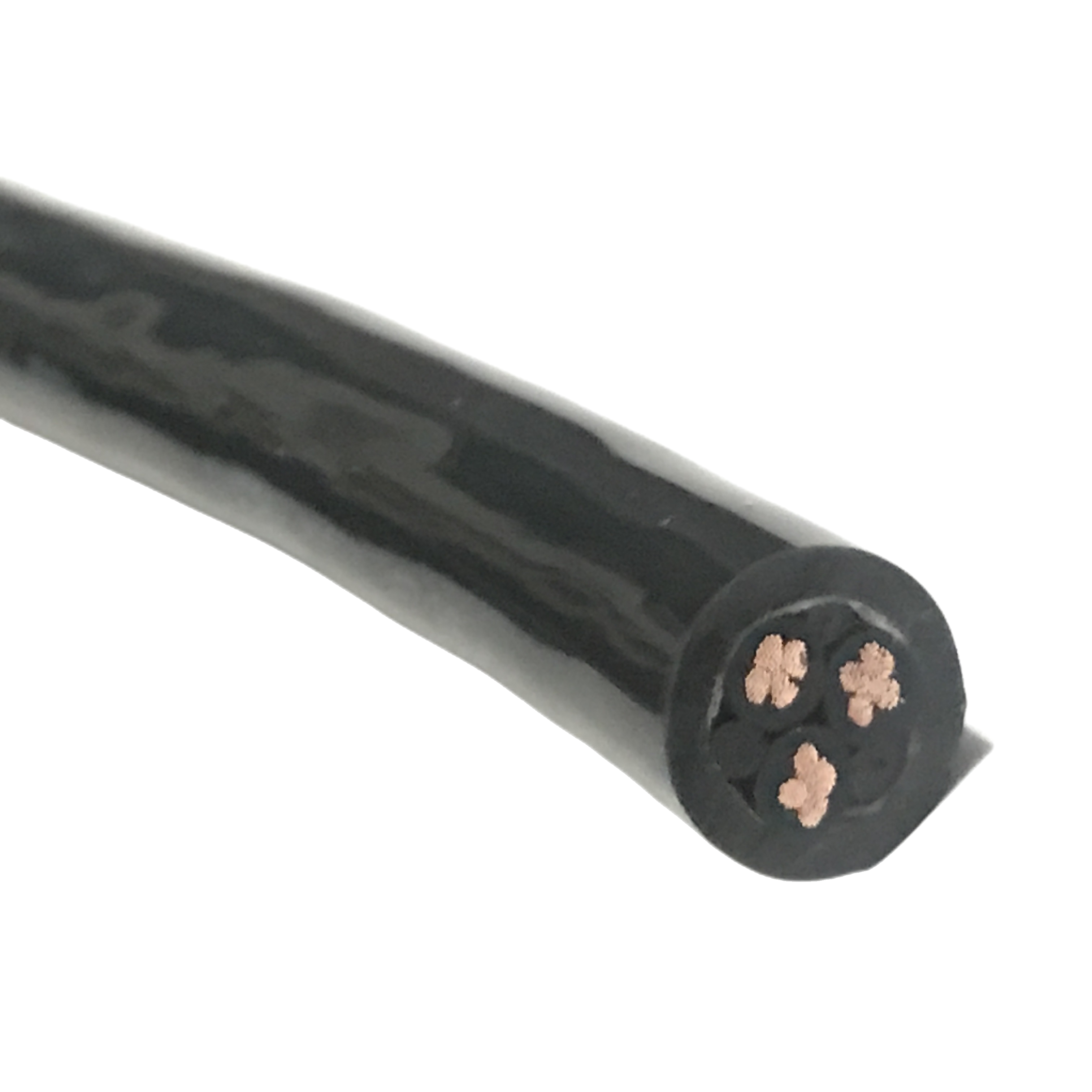
RST-DC-120 |
4 × 0.75 mm² |
None |
≥10M cycles |
4× OD dyn. |
7.2±0.3 |
−40 / +90 |
PUR std. |
|
RST-DC-130 |
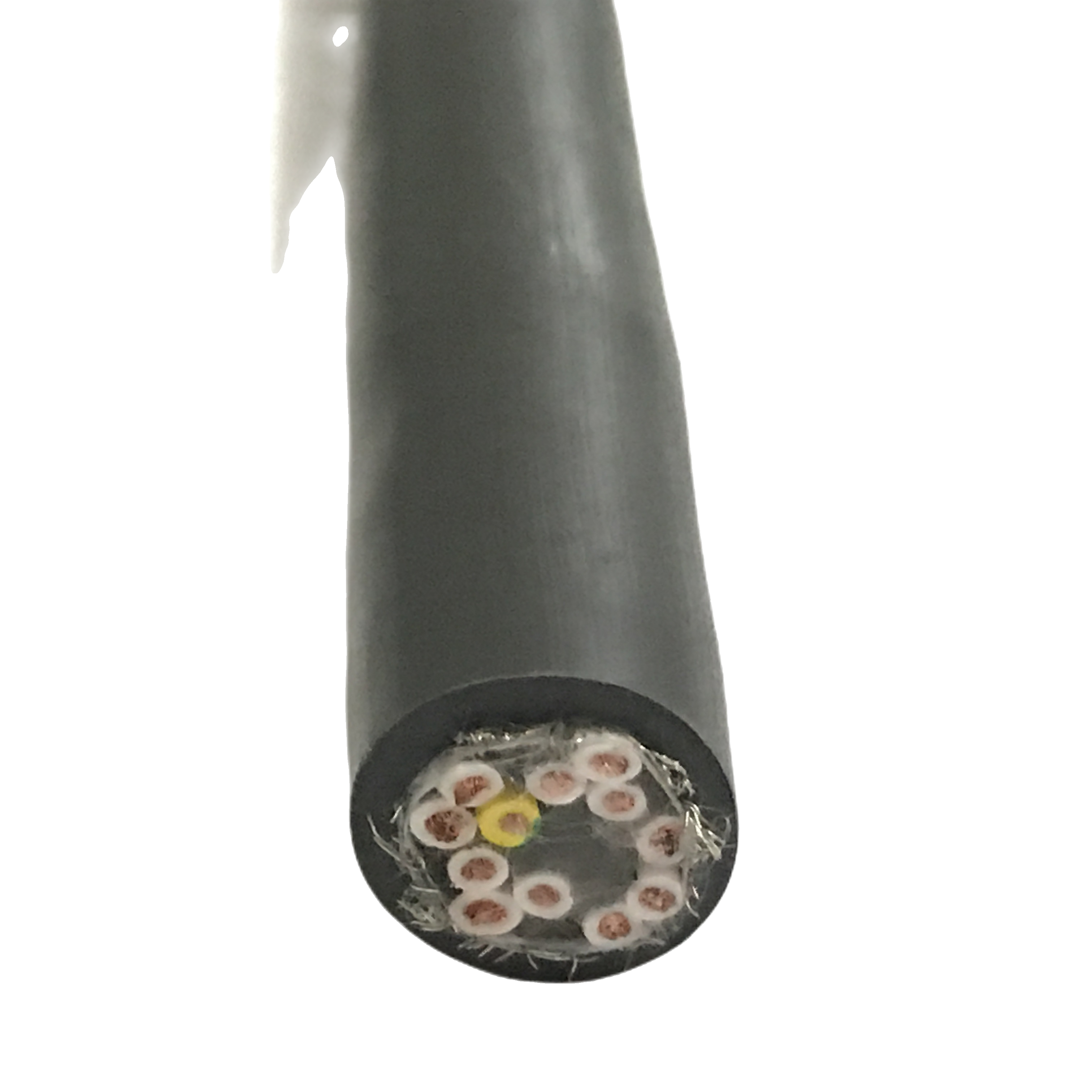
7 × 0.75 mm² |
None |
≥10M cycles |
4× OD dyn. |
9.0±0.3 |
−40 / +90 |
PUR std. |
|
RST-DC-140 |
12 × 0.75 mm² |
None |
≥10M cycles |
4× OD dyn. |
11.5±0.4 |
−40 / +90 |
PUR std. |
|
RST-DC-210 |
4 × 0.34 mm² |
Overall Cu braid |
≥10M cycles |
7.5× OD dyn. |
7.0±0.3 |
−40 / +90 |
PUR EMC |
|
RST-DC-220 |
4 × 0.75 mm² |
Overall Cu braid |
≥10M cycles |
7.5× OD dyn. |
8.8±0.3 |
−40 / +90 |
PUR EMC |
|
RST-DC-230 |
12 × 0.75 mm² |
Overall Cu braid |
≥10M cycles |
7.5× OD dyn. |
13.5±0.4 |
−40 / +90 |
PUR EMC |
|
RST-DC-310 |
3 × 1.5 mm² |
None |
≥5M cycles |
4× OD dyn. |
9.5±0.4 |
−40 / +90 |
PUR heavy-duty |
|
RST-DC-320 |
3×1.5+4×0.75 mm² |
Overall Cu braid |
≥5M cycles |
7.5× OD dyn. |
13.0±0.4 |
−40 / +90 |
PUR combined |
|
RST-DC-410 |
4 × 0.75 mm² |
None |
≥8M cycles |
4× OD dyn. |
7.8±0.3 |
−25 / +80 |
LSZH clean-room |
|
RST-DC-C (ETO) |
Per spec |
Per spec |
Per design |
Per design |
4–30 mm |
Per jacket |
PUR/LSZH/TPE |
Flex life note: 10M cycles applies to all control cable models (RST-DC-1xx, 2xx, 4xx) at 4× OD dynamic bend radius and 0.1 m/s traverse speed. RST-DC-3xx power cables are rated 5M cycles due to the higher conductor cross-section increasing bending stiffness. LSZH model (RST-DC-410) is rated 8M cycles — LSZH compounds are less elastic than PUR at the same hardness grade.
Complete Technical Specification
Conductor construction — Class 6 ultra-fine stranding
|
Parameter |
Specification |
|
Conductor standard |
IEC 60228 Class 6 — ultra-fine stranding for maximum flex fatigue life |
|
Wire count per core |
0.34 mm²: ≥ 130 wires · 0.75 mm²: ≥ 196 wires · 1.5 mm²: ≥ 280 wires · 2.5 mm²: ≥ 380 wires |
|
Individual wire diameter |
≤ 0.10 mm (0.34–0.75 mm²); ≤ 0.12 mm (1.5–2.5 mm²). Below the copper fatigue threshold at 4× OD dynamic bend radius; validated by fatigue life calculation per IEC 60228 Annex A |
|
Conductor material |
Oxygen-free copper (OFC) per ASTM B170; tin-plated option available for oil-immersion or high-humidity environments |
|
Lay length |
Controlled lay length 8–12× conductor OD; shorter lay = higher flex life but higher DC resistance; RST-DC uses 10× OD optimum for drag chain applications |
|
DC resistance (at 20 °C) |
0.34 mm²: ≤ 56.0 Ω/km · 0.75 mm²: ≤ 25.5 Ω/km · 1.5 mm²: ≤ 13.7 Ω/km · 2.5 mm²: ≤ 8.21 Ω/km |
Insulation and core identification
|
Parameter |
Specification |
|
Insulation compound |
Semi-rigid PVC (standard); XLPE (oil-resistant, 90 °C rated); LSZH for clean-room / semiconductor applications |
|
Insulation wall thickness |
0.34 mm²: 0.4 mm · 0.75 mm²: 0.5 mm · 1.5 mm²: 0.6 mm · 2.5 mm²: 0.7 mm; thin wall maintains cable flexibility while providing 300 V rated insulation |
|
Voltage rating |
300/500 V AC (control cables); 450/750 V AC (RST-DC-3xx power variants); withstand test 2,000 V AC / 1 min |
|
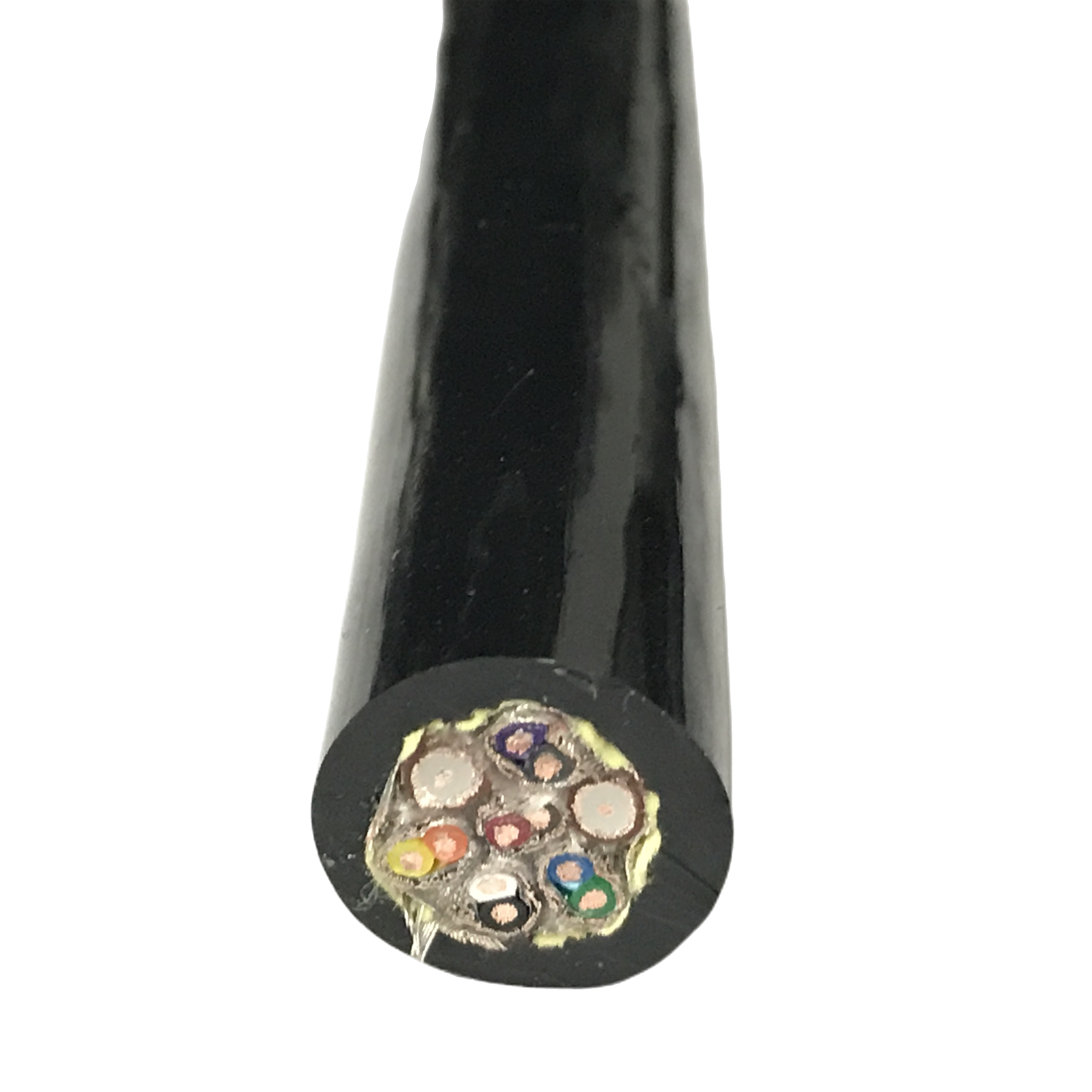
Core identification |
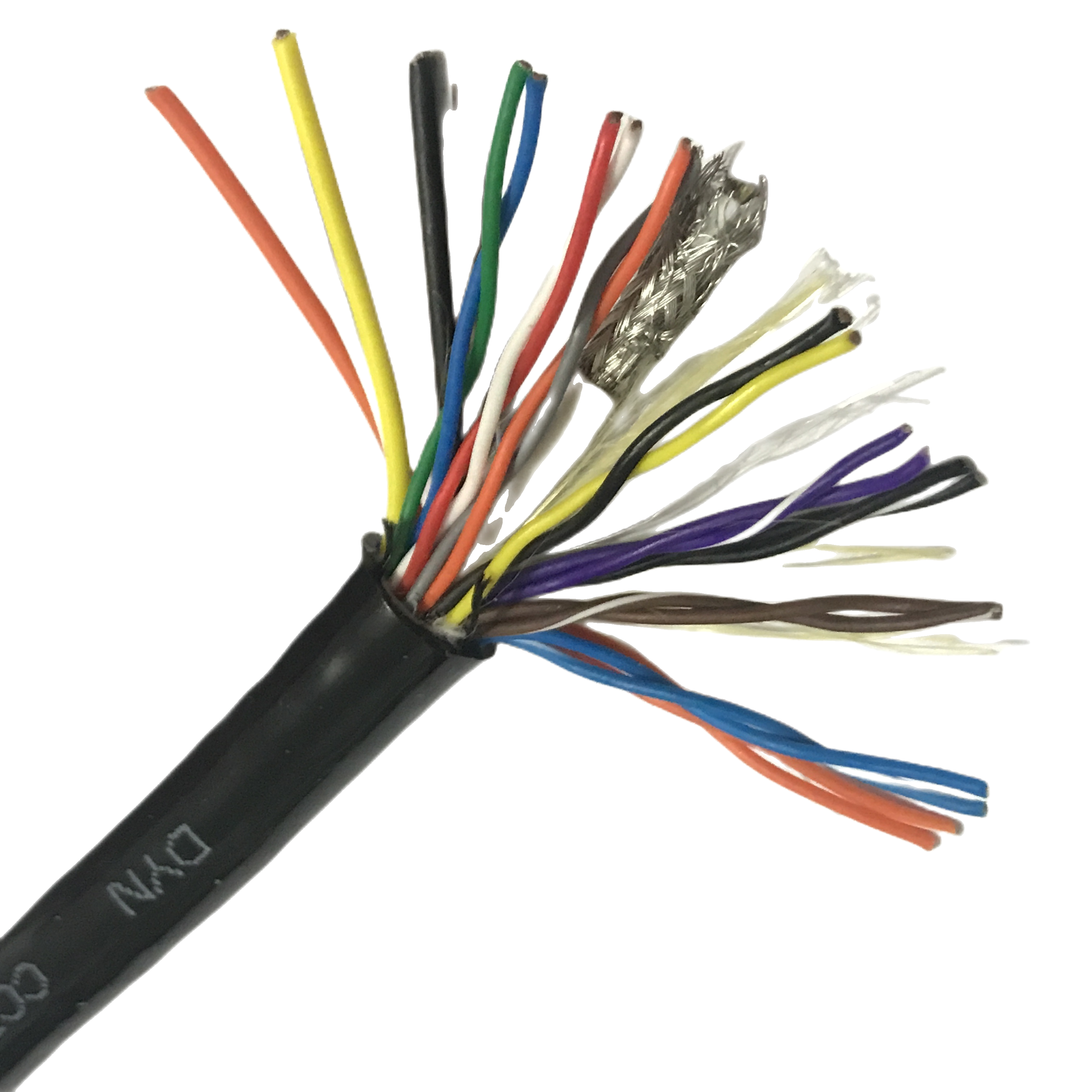
Colour-coded per IEC 60446 (PE: green-yellow; N: blue; L: brown; remaining: black with white numbering). Numbering printed at 50 mm intervals, readable through 10M flex cycles. |
|
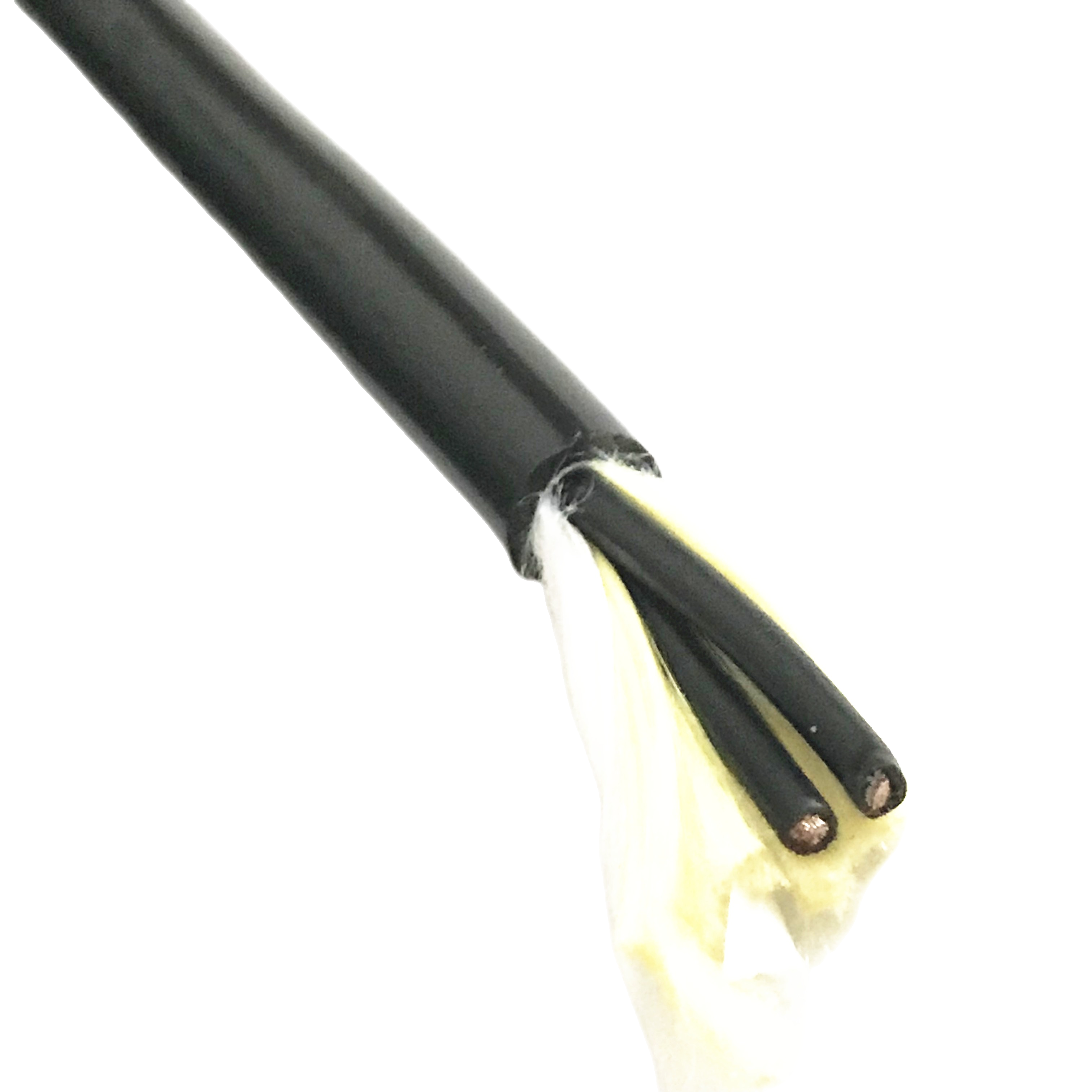
Core lay |
Cores stranded in concentric layers with reverse lay between layers; reverse lay prevents layer-to-layer unlaying during flex that causes uneven stress distribution |
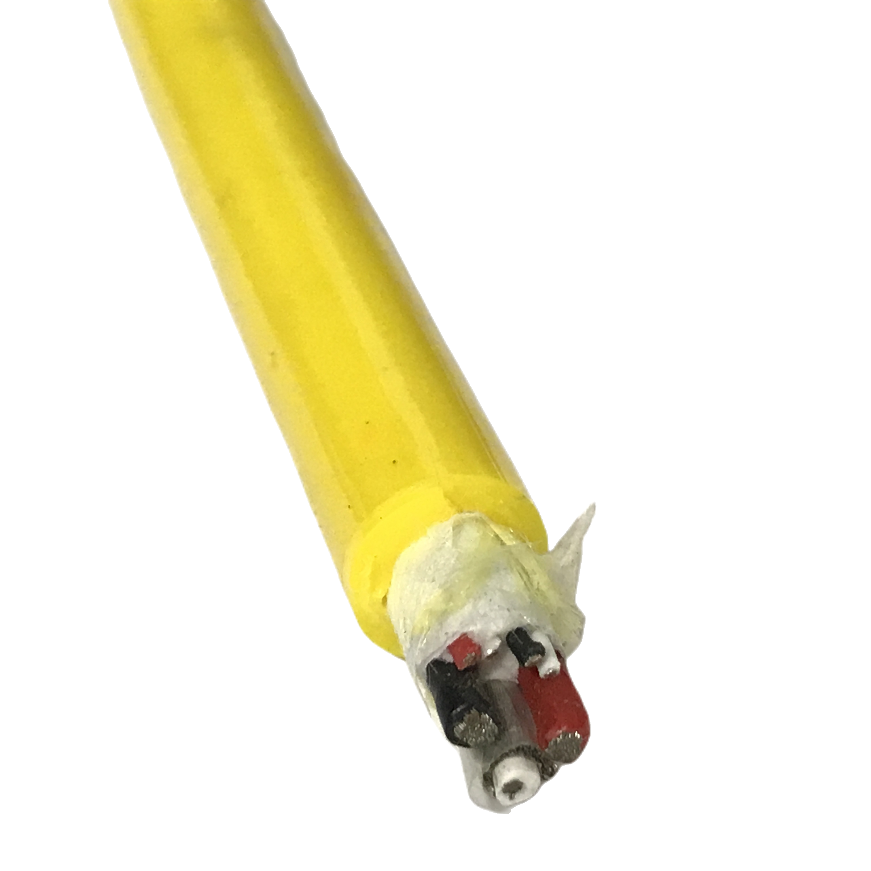
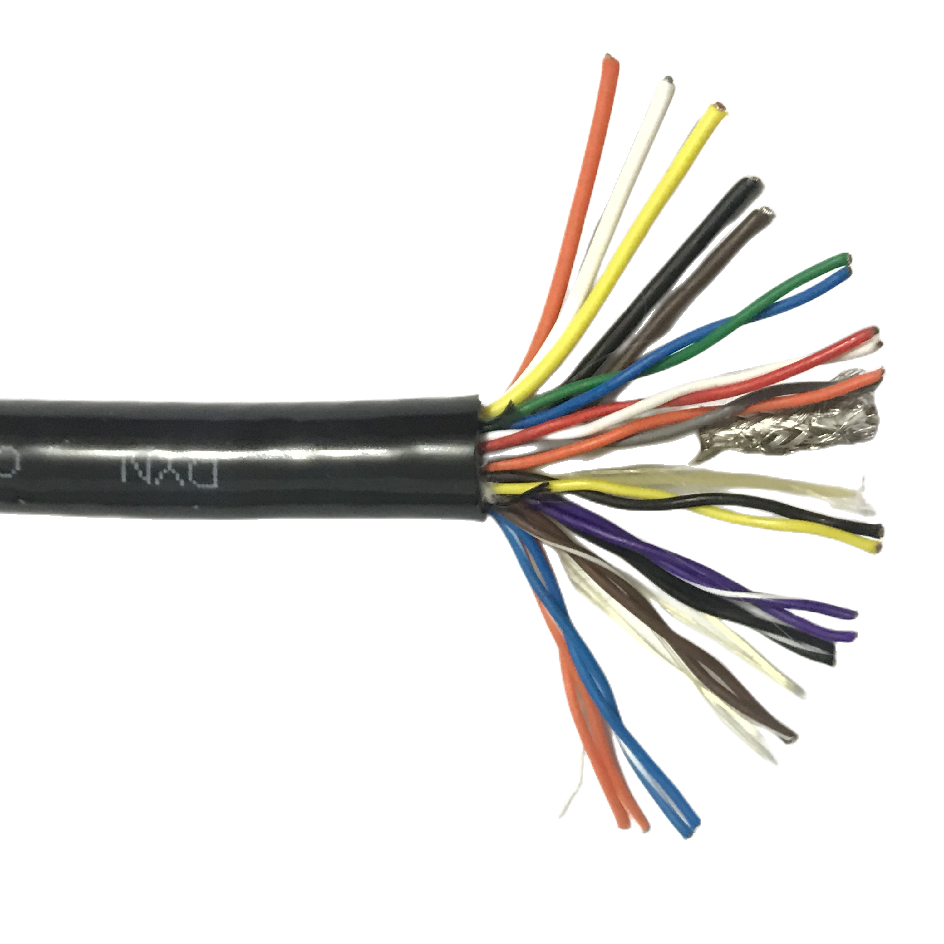
Shielding options for EMC-sensitive drag chain applications
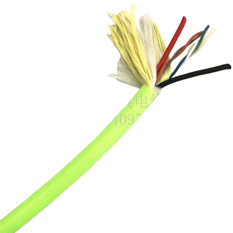
Shielded models (RST-DC-2xx and RST-DC-320) are specified in applications where the drag chain cable runs adjacent to servo drives, variable-frequency drives, or other sources of high-frequency electromagnetic interference.
|
Parameter |
Specification |
|
Shield type |
Tinned copper braid, ≥ 85% optical coverage; spiral wrap available ETO for higher coverage (95%) at reduced flex life (8M cycles) |
|
Transfer impedance |
< 50 mΩ/m at 1 MHz (braid); < 25 mΩ/m at 1 MHz (spiral + braid ETO); measured per IEC 62153-4-3 |
|
Min bend radius (shielded) |
7.5× OD dynamic; 3.5× OD static. Shielding braid adds torsional stiffness — shielded models cannot use the 4× OD minimum of unshielded variants |
|
Shield continuity under flex |
Transfer impedance verified at 0, 1M, 5M, and 10M cycle checkpoints; must remain < 50 mΩ/m throughout. Braid breakage produces a characteristic spike in the TI frequency curve that is distinguishable from cable-end contact resistance |
PUR jacket — abrasion resistance data
The PUR jacket is the primary mechanical protection layer. Its performance under abrasion contact with chain link surfaces determines when the cable requires replacement in a correctly designed drag chain system.
|
Parameter |
Specification |
|
Compound |
Polyurethane (PUR) 92 Shore A; ether-type PUR for oil resistance; oil immersion test per IEC 60811-2-1 Group 2 fluids; tensile retention ≥ 80% after 7-day immersion |
|
Abrasion resistance |
Taber abrasion: 15 mg/1000 cycles (CS-10 wheel, 500 g); versus PVC standard at 65 mg/1000 cycles. RST-DC jacket removes 4.3× less mass per 1000 abrasion cycles under equivalent contact load |
|
Operating temperature |
−40 °C to +90 °C continuous; cold-flex test at −40 °C: no cracking at 4× OD (IEC 60811-1-4); short-term excursion to +105 °C (15 min) permissible |
|
Chemical resistance |
Mineral oil, hydraulic oil, cutting fluid (oil-water emulsion), weak acids (pH ≥ 4), caustic solutions (pH ≤ 10); not resistant to concentrated aromatic solvents, ketones, or concentrated acids |
|
Flame retardancy |
IEC 60332-1 (single cable); LSZH variant meets IEC 60332-3-22 and EN 50575 Class Eca; halogen-free per IEC 60754-1 |
|
Surface friction coefficient |
Dynamic friction vs polished steel: μ = 0.28 ± 0.03 at 0.1 m/s traverse speed; low-friction surface texture reduces stick-slip contact with chain link interior |
Mechanical flex parameters
|
Parameter |
Specification |
|
Flex life (unshielded) |
≥ 10,000,000 cycles at 4× OD dynamic bend radius; criterion: no conductor break, resistance change < 10%, no jacket cracking |
|
Flex life (shielded) |
≥ 10,000,000 cycles at 7.5× OD; transfer impedance < 50 mΩ/m maintained throughout |
|
Min dynamic bend radius |
Unshielded: 4× OD · Shielded: 7.5× OD · Power variants (RST-DC-3xx): 5× OD unshielded, 10× OD shielded |
|
Max traverse speed |
Standard: 5 m/s · High-speed ETO (reinforced filler): 10 m/s · At speed > 5 m/s, centrifugal loading of the cable in the chain trough requires filler elements bonded to the jacket inner surface to prevent core migration |
|
Max acceleration |
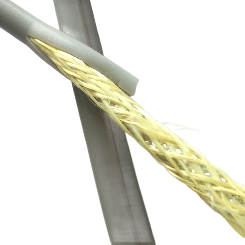
50 m/s² standard; 100 m/s² ETO high-acceleration variant with Kevlar tensile member |
|
Torsion resistance |
RST-DC is a pure flex cable, not a torsion cable. For applications with combined flex and torsion (robot arm twist axes), specify RST-DC-C ETO with torsion-rated helical conductor lay |
Drag Chain Installation Design: Parameters That Determine Cable Life
How drag chain geometry affects PUR flexible control cable service life
Drag chain cable life is determined as much by the chain installation geometry as by the cable’s own flex rating. A cable rated for 10,000,000 cycles will fail in 500,000 cycles if the chain radius is below the cable’s minimum dynamic bend radius, or if the chain trough is too wide for the cable OD — allowing the cable to cross-wind between cycles.
The following parameters must be confirmed before specifying cable model and OD. Rousheng’s application engineering team reviews chain geometry drawings and confirms the RST-DC model and fill ratio before order confirmation — this review is provided at no charge.
Chain radius and cable minimum bend radius
The chain’s inner radius at the bend point must be ≥ the cable’s minimum dynamic bend radius. For RST-DC unshielded models: minimum dynamic bend radius = 4× cable OD. For a 7.2 mm OD cable (RST-DC-120), the minimum chain inner radius is 4 × 7.2 = 28.8 mm.
If the chain radius is below this value, the cable’s bend stress exceeds the conductor fatigue limit regardless of how many flex cycles the cable is rated for. Cable life in this condition is unpredictable and typically falls below 200,000 cycles.
Chain trough width and cable fill ratio
In a multi-cable drag chain, the total cable cross-section must not exceed 60% of the chain trough’s cross-sectional area. This is the standard fill ratio that allows cables to rearrange during direction changes without binding.
Below 60% fill: cables slide freely in the trough and do not exert excessive compressive force on adjacent cables. Above 60% fill: cables bind against each other and the chain link walls during direction change, generating compressive loads that accelerate jacket abrasion and cross-section ovality.
Cable separation and fixing intervals
RST-DC cables must be fixed at the chain’s fixed end with a cable clamp applying 60–80% of the cable OD as clamping width — tight enough to prevent cable migration into the chain during rapid retraction, loose enough not to deform the circular cross-section.
At the moving end, allow a service loop of 150–200% of the cable OD before the clamp. This loop absorbs the small amount of longitudinal migration that occurs in every cable during flex cycling — preventing the cable from being placed in tension as it reaches the end of stroke.
|
DESIGN RULE SUMMARY |
1. Chain inner radius ≥ cable minimum dynamic bend radius (4× OD unshielded; 7.5× OD shielded) 2. Total cable fill ≤ 60% of chain trough cross-sectional area 3. Fixed-end clamp width: 60–80% of cable OD; 60–80 N clamping force 4. Moving-end service loop: 1.5–2.0× cable OD before the clamp 5. Do not bundle cables with cable ties inside the chain trough — ties create local compression points that accelerate abrasion |
Application Selection Guide
Choosing the right flexible control cable for your drag chain axis
The RST-DC model is determined by four parameters: signal type (control or power), EMC shielding requirement, installation environment (oil, clean-room, standard), and cycle rate / traverse speed. The table below maps common machine axis types to the recommended model.
|
Machine axis type |
Signal type |
EMC required |
Recommended model |
Selection rationale |
|
CNC linear axis (X/Y/Z) |
Control 24 V DC |
Yes (servo drive nearby) |
RST-DC-220 |
4 × 0.75 mm² covers limit switches, tool changer signals, and encoder screen connections; overall braid shields against servo drive EMI |
|
Pick-and-place robot (SCARA) |
Control + 24 V power |
Yes |
RST-DC-230 |
12 × 0.75 mm² covers all I/O in a single cable; 10M cycle rating at 13.5 mm OD — verify chain inner radius ≥ 101 mm for shielded model |
|
Conveyor transfer carriage |
Control only |
No (low-noise environment) |
RST-DC-130 |
7 × 0.75 mm² adequate for carriage position, sensor, and valve signals; unshielded reduces OD to 9.0 mm, fitting smaller chain troughs |
|
Gantry crane (horizontal traverse) |
Power + control |
Optional |
RST-DC-320 |
3 × 1.5 mm² power + 4 × 0.75 mm² control in single cable; reduces chain trough occupancy versus two separate cables; 5M cycle rating adequate for crane duty (≤ 200 moves/hr) |
|
Semiconductor handling robot |
Control + signal |
Yes (strict EMC) |
RST-DC-410 (LSZH) |
LSZH jacket required for clean-room and fab environments; no halogen outgassing; 8M cycle rating at 4× OD; confirm chain radius ≥ 31.2 mm (4 × 7.8 mm OD) |
|
High-speed linear motor axis (> 3 m/s) |
Control + encoder |
Yes |
RST-DC-C ETO |
Standard RST-DC is rated to 5 m/s. Above 3 m/s, centrifugal loading requires bonded-filler ETO design. Specify traverse speed, stroke length, and acceleration in enquiry |
Jacket Material Comparison: PUR vs PVC vs TPE for Drag Chain Applications
Why PUR outperforms PVC and TPE as a drag chain cable jacket
The jacket compound comparison below is drawn from Rousheng’s accelerated wear testing programme. All three materials were tested on the same cable core assembly in the same chain trough geometry at the same traverse speed and compressive load.
|
Property |
PUR (RST-DC standard) |
PVC (generic flex cable) |
TPE (thermoplastic elastomer) |
|
Abrasion resistance |
15 mg / 1,000 cycles (Taber CS-10, 500 g) |
65 mg / 1,000 cycles |
28 mg / 1,000 cycles |
|
Cold flex (−40 °C) |
No cracking at 4× OD per IEC 60811-1-4 |
Cracks at −25 °C at 4× OD |
No cracking at −30 °C |
|
Oil resistance |
Excellent — ether-type PUR; tensile retention ≥ 80% after 7-day immersion |
Moderate — oil causes plasticiser migration in PVC over 6–12 months |
Good — TPE resists most mineral oils |
|
Flex life at 4× OD |
≥ 10M cycles (RST-DC series) |
1–3M cycles typical (stiffens as plasticiser migrates) |
4–8M cycles (softer than PUR; more compressible in chain trough) |
|
Halogen content |
Halogen-free; IEC 60754-1 compliant |
Contains chlorine — not halogen-free |
Halogen-free |
|
Cost vs PUR |
Baseline (100%) |
60–70% of PUR |
80–90% of PUR |
|
Recommendation |
Default for all drag chain applications with ≥ 1M cycle requirement or oil exposure |
Not recommended for drag chain applications; adequate for static-flex installation only |
Suitable for medium-duty drag chain (< 4M cycles); lower cost alternative where oil exposure is absent |
Common Drag Chain Cable Installation Failures: Causes and Corrections
Field diagnostic guide for flexible control cable failures in drag chains
These failure patterns are identified from Rousheng’s field service records. Each includes the measurable threshold at which the failure becomes detectable.
|
Symptom |
Root cause |
Measurable threshold |
Correction |
|
Intermittent signal loss at end of stroke |
Conductor work-hardening — Class 5 stranding specified instead of Class 6 |
Resistance increase > 10% at bend reversal point vs straight section |
Replace with Class 6 (≥ 196 wires/core for 0.75 mm²). Verify by measuring per-core resistance with Kelvin bridge at full bend vs straight — Class 5 shows > 10% resistance increase at 500,000 cycles; Class 6 remains within 2%. |
|
Jacket worn through at chain link contact points |
Cable fill ratio too high (> 60%) — cables under compressive load from adjacent cables |
Visible abrasion wear within 200,000 cycles |
Calculate total cable cross-section fill ratio. If > 60%: split into two chain troughs, increase chain width, or reduce cable count. PVC jacket accelerates abrasion 4× faster than PUR — confirm jacket compound if sourcing from multiple suppliers. |
|
Cable corkscrew — cable twists in trough during flex |
Cable installed with pre-existing twist, or torsional side-load from misaligned chain end clamps |
Visible twist after 10,000 cycles; cable exits trough at direction-change point |
Unroll RST-DC cable from drum — do not pull from coil end (introduces twist). Verify both end clamps are aligned with the chain direction of travel to within ±3°. Torsion applications require RST-DC-C ETO torsion variant. |
|
Cross-section collapse — cable becomes oval, fits loosely in chain trough |
Fill ratio too low (< 30%) — cable migrates laterally and folds in trough |
Ovality > 10% measured with calliper at bend point after 100,000 cycles |
Minimum fill ratio is 30% — too loose is as problematic as too tight. Use spacers between cables to maintain position, or select a smaller chain trough width. Alternatively, increase cable OD to match trough dimensions. |
|
Shielded cable EMC performance degrades after 2–3M cycles |
Braid shield wire breakage at bend reversal — exceeded shielded minimum bend radius (7.5× OD) |
Transfer impedance rises above 100 mΩ/m at 1 MHz |
Verify chain inner radius ≥ 7.5× cable OD for shielded models. If chain radius cannot be increased: use RST-DC-C ETO with spiral-wound inner shield (maintains lower transfer impedance at tighter bend radii, 8M cycle rating at 6× OD). |
Frequently Asked Questions
What is the difference between a PUR flexible control cable and a standard PVC flexible cable?
PVC flexible cables (Class 5 stranding, 65–75 Shore A jacket) are designed for occasional flexing — installation bending, periodic repositioning. They are not drag chain cables. The differences that matter for drag chain applications: Class 6 versus Class 5 stranding (4× the wire count, far lower bend stress per wire); PUR 92 Shore A versus PVC 75 Shore A jacket (4× abrasion resistance at equivalent contact load); foamed PE filler versus void filling (cross-section ovality control under compressive load). In drag chain applications, a PVC flexible cable typically fails in 500,000–1,000,000 cycles. RST-DC is rated 10,000,000.
How do I calculate the minimum chain inner radius for my RST-DC cable?
Multiply the cable OD by the minimum dynamic bend radius factor. For unshielded RST-DC models: minimum chain inner radius = 4 × cable OD. For shielded models: 7.5 × cable OD. For power variants (RST-DC-3xx): 5 × cable OD unshielded, 10 × cable OD shielded. Example: RST-DC-220 shielded, OD 8.8 mm — minimum chain inner radius = 7.5 × 8.8 = 66 mm. If your chain has a tighter radius, contact our engineering team for an ETO design with a smaller outer diameter or a torsion-capable construction.
Can RST-DC cables be used in robot arm torsion axes as well as drag chains?
Standard RST-DC models are designed for single-axis flex — bend reversal in one plane, no torsion. Robot arm axes that combine flexing with rotation (wrist joints, twist axes) generate torsional loading that the helical conductor lay in a standard drag chain cable cannot accommodate. For combined flex-and-torsion applications, specify RST-DC-C ETO with torsion-rated construction (modified lay length, Kevlar tensile member, alternative filler geometry). Describe the joint motion type and the required flex angle and rotation angle in your enquiry.
What is the maximum traverse speed the RST-DC series supports?
Standard RST-DC models are rated to 5 m/s traverse speed. Above 3 m/s, centrifugal acceleration of the cable in the chain trough exerts lateral forces on the cable that cause core migration within the jacket if the filler elements are not bonded. The standard RST-DC uses unbonded foamed PE fillers — adequate to 5 m/s. For traverse speeds above 5 m/s (up to 10 m/s), an ETO high-speed variant with bonded fillers and a reinforced outer jacket is available. Specify traverse speed, stroke length, and acceleration in your enquiry.
Is RST-DC cable available with halogen-free insulation for clean-room applications?
Yes — RST-DC-410 uses an LSZH outer jacket and halogen-free insulation throughout. It is rated 8M flex cycles at 4× OD (compared to 10M for PUR models — LSZH compounds are less elastic than PUR at equivalent hardness). The LSZH jacket complies with IEC 60754-1 for halogen content (< 0.5% HCl equivalent) and IEC 61034-2 for smoke density (≥ 60% light transmission). RST-DC-410 is the standard specification for semiconductor fab, pharmaceutical, and food-processing drag chain installations where no halogen outgassing is permitted.
Request Samples, Test Data, or a Quotation
How to get the right flexible control cable specified for your drag chain
Rousheng provides a free application engineering review — chain geometry confirmation, bend radius check, and fill ratio calculation — before order placement. Cable samples with flex life test data and abrasion test report are available on request. For a complete single-reply response, include:
- Machine axis type and brief description of the motion (traverse speed, stroke length, cycle rate)
- Chain make and model if known, or inner radius, trough width, and number of cables
- Core count and cross-section required (or list of signals / currents to be carried)
- EMC shielding requirement: yes/no; if yes, interference source type (servo drive, VFD, other)
- Installation environment: standard industrial, oil-immersion, clean-room, outdoor
- Traverse speed (m/s) and peak acceleration (m/s²)
- Required service life in cycles or years at stated cycle rate
- Jacket compound preference: PUR (default), LSZH, or TPE
|
CONTACT |
Email: Jerry@rstlkable.com WhatsApp / Phone: +86 134 8219 7396 Address: No. 2591 Fengzhe Road, Fengxian District, Shanghai, China Sample requests: state RST-DC model number, cable OD, and chain geometry for targeted sample selection. |