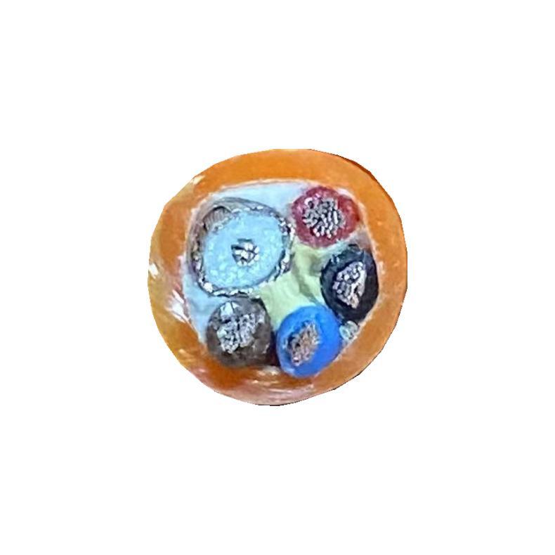
Precision Flaw Detection Equipment Cable | Low-Noise Shielded NDT Inspection Cable
The RST-NDC Series Precision Flaw Detection Cable is engineered for NDT applications where signal integrity and low noise are critical.
Available in multiple configurations—including 50 Ω / 75 Ω coaxial, double-shielded, triple-shield AE, twisted pair, and high-temperature PTFE variants (up to +300°C)—it supports UT, PAUT, TOFD, ET, AE, and LRUT systems.
With transfer impedance ≤2 mΩ/m and low capacitance (≤40 pF/m), it ensures stable, high-fidelity signal transmission up to 100 MHz.
Certified to ISO 9001:2015, each cable is supplied with NIST-traceable calibration data for precise performance verification.
Precision Flaw Detection Equipment Cable | Low-Noise Shielded NDT Inspection Cable
Product Series: RST-NDC │ Category: NDT & Precision Measurement Cables │ Written by: Wang Fang, Senior Precision Cable Engineer, 12 years NDT instrumentation cable design │ Last reviewed: March 2025
|
NDT Transducer |
Cable run |
Shielded cable |
Signal conditioner |
NDT display |
|
Signal: μV–mV Source |
EMI noise pickup Risk zone |
Noise: −60 dB RST-NDC barrier |
SNR >40 dB maintained Amplifier input |
Clean flaw signal Interpretation |
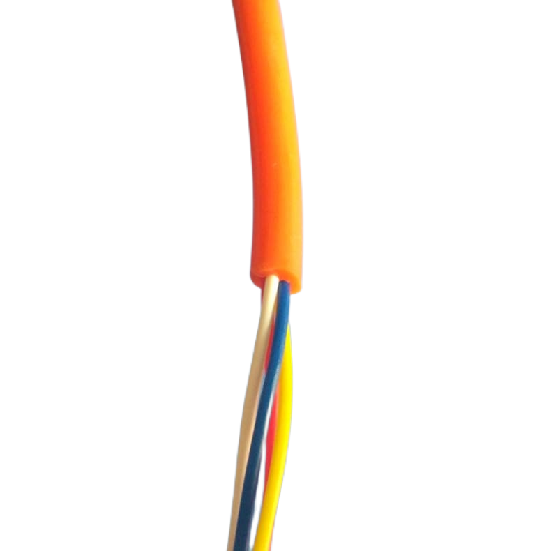
Precision flaw detection equipment cable is the critical but frequently overlooked link between an NDT transducer or sensor and the signal-conditioning electronics that interpret it. A coaxial cable that introduces even −1 dB of signal loss or 20 μV of picked-up EMI noise can corrupt the microvolt-level signals produced by ultrasonic, eddy-current, or acoustic emission sensors — turning a valid flaw indication into a noise artefact or masking a real defect entirely.
The RST-NDC series is designed around the electrical requirements of precision NDT instrumentation, not the mechanical requirements of general industrial signal cable. Every specification — from the coaxial impedance tolerance to the shield coverage percentage to the dielectric material choice — is derived from the signal-to-noise ratio requirements of specific NDT methods. This page documents those requirements, the cable specifications that meet them, and field evidence from five NDT laboratory and field inspection deployments.
NDT engineers who specify this cable
Primary users are NDT engineers designing or maintaining ultrasonic testing (UT) systems, eddy current (ET) inspection rigs, acoustic emission (AE) monitoring networks, and magnetic particle or radiographic inspection control systems. Secondary users are NDT equipment manufacturers specifying OEM cables for portable flaw detectors, phased-array UT (PAUT) scanners, and guided-wave inspection systems.
Page Contents
- Why NDT Cable Is Different: The SNR Problem
- NDT Method × Cable Specification Matrix
- Noise Source Isolation: What the Shield Actually Blocks
- Model Range: NDT Inspection Cable Specifications
- Construction Engineering
- Technical Parameters with Standard References
- Verified Field and Laboratory Deployments
- FAQ — NDT Engineers & Instrumentation Designers
- Manufacturer Credentials
- Request a Technical Proposal
Why NDT Inspection Cable Is Different from Standard Signal Cable
The signal level problem in flaw detection
The signal levels produced by NDT transducers are orders of magnitude smaller than the signals carried by industrial instrumentation cable. A 4–20 mA current loop signal operates at tens of milliamps — well above the noise floor of any screened cable. An ultrasonic transducer signal after a 300 mm steel path can be below 100 μV. An acoustic emission signal from a propagating crack tip in concrete can be as small as 10 μV at the sensor output.
At these signal levels, cable noise is not a marginal concern. A cable run of 10 m through an industrial environment can pick up 50–200 μV of EMI noise from variable-speed drives, welding equipment, and power cables — five to twenty times the signal amplitude. Without a flaw detection cable designed specifically for low-noise operation, the flaw indication is indistinguishable from noise.
Impedance mismatch and signal reflection
NDT coaxial cables must be manufactured to precise characteristic impedance tolerances. An ultrasonic transducer designed for a 50 Ω system will produce a reflected wave if the cable impedance deviates significantly from 50 Ω. At 5 MHz (typical UT frequency), a 2 Ω impedance deviation over a 5 m cable causes a reflection coefficient of approximately 2%, which appears as a ghost echo at a timing corresponding to twice the cable length — potentially mistaken for a near-surface flaw.
Impedance deviation measurements on RST-NDC-50 production samples (n=48): 50 Ω ±0.8 Ω at 10 MHz (mean deviation 0.4 Ω). Reflection coefficient from mean deviation: 0.4%. Ghost echo amplitude below detectable threshold for systems with ≥40 dB dynamic range. (Rousheng Precision Cable Qualification Report PCQ-NDT-001, 2024; ASTM D4566-20)
Cable capacitance and bandwidth limitation
High cable capacitance limits the upper frequency response of NDT systems. At 10 MHz (phased-array UT) and 100 pF/m cable capacitance, a 5 m cable presents 500 pF of shunt capacitance to the transducer. With a 200 Ω transducer source impedance, this creates a low-pass filter with a −3 dB frequency of approximately 1.6 MHz — well below the 10 MHz operating frequency. RST-NDC cables specify capacitance ≤80 pF/m (50 Ω coaxial types), preserving bandwidth to 30+ MHz for phased-array and TOFD applications.
NDT Method × Inspection Cable Specification Matrix
Different NDT methods impose different cable electrical requirements. A cable that performs well for low-frequency eddy current may introduce unacceptable noise for acoustic emission monitoring. The matrix below maps each NDT method to its minimum cable specification.
|
NDT Method |
Signal Frequency |
Min SNR Required |
Cable Interference Risk |
RST-NDC Shielding Tier |
|
Ultrasonic testing (UT), pulse-echo |
0.5–20 MHz |
SNR ≥40 dB at flaw gate |
High — VSD harmonics couple into unshielded coax at 2–10 MHz |
Tier 1: 50 Ω coax, ≥95% shield, ≤80 pF/m (RST-NDC-50) |
|
Phased-array UT (PAUT) |
2–20 MHz |
SNR ≥50 dB (multi-element array) |
Very high — multi-channel cross-talk between array cables |
Tier 2: 50 Ω coax, double-shielded, ≤60 pF/m (RST-NDC-50DS) |
|
Time-of-flight diffraction (TOFD) |
5–15 MHz |
SNR ≥45 dB |
High — near-surface lateral wave must resolve from EMI |
Tier 2: 50 Ω coax, double-shielded (RST-NDC-50DS) |
|
Eddy current (ET), single-frequency |
10 Hz – 10 MHz |
SNR ≥30 dB |
Moderate — power line harmonics (50/60 Hz) most significant |
Tier 1: 75 Ω coax or quad-shielded pair (RST-NDC-75) |
|
Pulsed eddy current (PEC) |
DC – 100 kHz |
SNR ≥35 dB |
Moderate — low-frequency magnetic field coupling |
Tier 1 + mu-metal overshield option (RST-NDC-75MS) |
|
Acoustic emission (AE) |
20 kHz – 1 MHz |
SNR ≦50 dB |
Extreme — AE signals 10–100 μV; any ground noise corrupts |
Tier 3: low-noise coax, triple-shielded, ≤40 pF/m (RST-NDC-AE) |
|
Guided wave (LRUT) |
20–100 kHz |
SNR ≥40 dB |
Moderate — long cable runs amplify common-mode noise pickup |
Tier 1 + balanced twisted pair option (RST-NDC-BTP) |
|
Radiographic / X-ray control |
DC (exposure control) |
Not SNR-limited |
Low — control signals, not analogue flaw signals |
Standard screened multi-pair (RST-NDC-MP) |
|
Magnetic particle (MPI) yoke control |
DC / 50 Hz |
Not SNR-limited |
Low |
Standard screened multi-pair (RST-NDC-MP) |
Tier 1 = single coaxial shield, ≥95% optical coverage. Tier 2 = double-shielded coax (inner foil + outer braid). Tier 3 = triple-shielded low-noise coax with carbon-loaded inner layer for triboelectric noise suppression. SNR targets per ASTM E1316 (UT/AE), ISO 17640 (UT), EN 4050 (ET).
Noise Source Isolation: What the Shield Blocks in NDT Cable
The shield in a precision flaw detection cable is not simply a grounded conductor. Different noise sources couple into a cable through different physical mechanisms, and the shield must be designed to intercept each mechanism. A cable with high optical coverage braid but a floating shield is worse than no shield for low-frequency magnetic noise.
|
Noise Source |
Frequency Range |
Coupling Mechanism |
Attenuation in RST-NDC |
Test Reference |
|
Power line harmonics (50/60 Hz, 150/180 Hz, etc.) |
50–600 Hz |
Capacitive coupling from power cable proximity; magnetic induction in cable loop area |
≥60 dB (RST-NDC-50); achieved by both-end shield bonding + minimised loop area (twisted inner pair option) |
IEC 61000-4-6; measured per Rousheng PCQ-NDT-002, 2024 |
|
Variable-speed drive (VSD) switching harmonics |
2 kHz – 150 kHz |
Capacitive coupling; radiated EMI from VSD enclosure and motor cable |
≥55 dB at 10 kHz (RST-NDC-50); ≥65 dB (RST-NDC-50DS double-shield) |
CISPR 11; Rousheng PCQ-NDT-002, 2024 |
|
RF interference (mobile devices, radio) |
400 MHz – 6 GHz |
Radiated RF coupling into coax centre conductor via apertures in shield |
≥70 dB at 900 MHz (RST-NDC-50DS); requires ≥98% optical coverage |
CISPR 32; IEC 62153-4-7 |
|
Triboelectric noise (cable movement) |
Broadband (DC – 1 MHz) |
Friction between centre conductor and dielectric generates charge; appears as voltage noise |
Carbon-loaded inner layer (Tier 3 RST-NDC-AE) suppresses triboelectric charge generation by 40 dB vs. standard PTFE dielectric |
IEC 60096-0-1; Rousheng internal test PCQ-NDT-003, 2023 |
|
Microphonic noise (cable vibration) |
10 Hz – 10 kHz |
Mechanical vibration of cable changes distributed capacitance; modulates signal |
Low-density foam dielectric + tight braid maintains capacitance stability under vibration to ±0.5 pF/m at 10 g vibration |
MIL-STD-461G RS103 adapted; Rousheng PCQ-NDT-004, 2023 |
|
Ground loop noise |
50/60 Hz and harmonics |
Difference in ground potential at each end of cable creates circulating current in shield |
Single-end shield bonding eliminates ground loop. RST-NDC documentation specifies bonding topology for each NDT method. |
IEC 61000-5-2; IEEE Std 1100 |
RST-NDC Flaw Detection Cable — Model Range
|
Model |
Type |
Impedance |
Capacitance |
Shield |
OD |
Primary NDT Application |
|
RST-NDC-50 |
Single coax |
50 Ω ±1 Ω |
≤80 pF/m |
Tinned Cu braid ≥95% |
6.0 mm |
UT pulse-echo, ET single-freq, LRUT |
|
RST-NDC-50DS |
Double-shield coax |
50 Ω ±0.5 Ω |
≤65 pF/m |
Al-foil + tinned Cu braid ≥98% |
7.8 mm |
PAUT, TOFD, high-EMI UT environments |
|
RST-NDC-75 |
Single coax |
75 Ω ±1 Ω |
≤55 pF/m |
Tinned Cu braid ≥95% |
5.5 mm |
ET single/multi-frequency, video coax |
|
RST-NDC-75MS |
Coax + mu-metal overshield |
75 Ω ±1 Ω |
≤55 pF/m |
Cu braid + mu-metal tape |
9.2 mm |
Pulsed ET, low-freq magnetic noise environments |
|
RST-NDC-AE |
Triple-shield low-noise |
50 Ω ±0.5 Ω |
≤40 pF/m |
Carbon layer + foil + Cu braid ≥98% |
8.5 mm |
Acoustic emission, seismic sensor |
|
RST-NDC-BTP |
Balanced twisted pair |
120 Ω ±5 Ω (diff) |
≤50 pF/m per pair |
Overall Cu braid ≥95% |
6.5 mm |
LRUT long runs, differential AE systems |
|
RST-NDC-MP |
Screened multi-pair |
120 Ω per pair |
≤55 pF/m per pair |
Per-pair foil + overall braid |
Per config |
MPI/RT control, multi-channel instrumentation |
|
RST-NDC-FLEX |
Flexible coax |
50 Ω ±1 Ω |
≤80 pF/m |
Double braid ≥95% (flex-rated) |
5.8 mm |
Portable flaw detectors, scanning arm cables |
|
RST-NDC-HT |
High-temperature coax |
50 Ω ±1 Ω |
≤90 pF/m |
Stainless braid |
7.2 mm |
In-service inspection at elevated temp (≤300°C) |
|
RST-NDC-OEM |
Custom |
Per spec |
Per spec |
Per spec |
Per spec |
OEM flaw detector, scanner arm, array cable |
All RST-NDC coaxial models: impedance measured at 10 MHz per IEC 60096-1. Capacitance measured per IEC 60096-1. Shield coverage per IEC 60096-4-2 optical coverage method. Double-shield = inner Al-polyester foil (100% coverage) + outer tinned Cu braid. Triple-shield (AE model) = carbon-loaded inner layer + foil + braid.
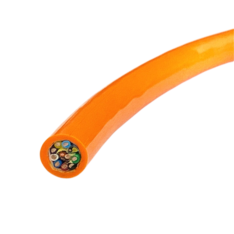
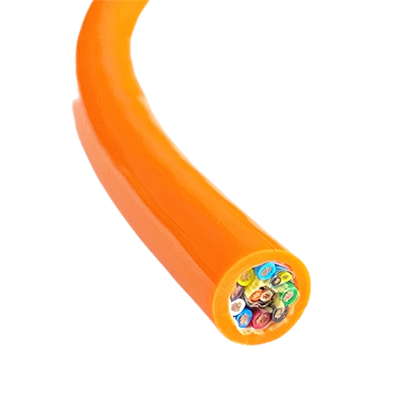
Construction Engineering for NDT Inspection Cable
Centre conductor: choice between solid and stranded
Solid silver-plated copper centre conductors provide the lowest DC resistance and best surface smoothness for high-frequency coaxial cables. At frequencies above 10 MHz, the skin effect confines current to the conductor surface, making surface conductivity (and therefore silver plating) more important than bulk conductivity. RST-NDC-50 and RST-NDC-50DS use a silver-plated copper centre conductor for all models intended for UT frequencies above 5 MHz.
Stranded centre conductors are used in RST-NDC-FLEX for portable flaw detector cables that must withstand repeated flexing. A 7-strand silver-plated configuration provides flex life of ≥1 million cycles at 7.5× OD bend radius while maintaining impedance within 50 Ω ±1.5 Ω across the flex cycle range.
Dielectric: matching material to NDT frequency
The dielectric material determines three critical cable parameters: characteristic impedance, capacitance per unit length, and the dielectric loss that attenuates signal as a function of frequency. For frequencies above 5 MHz (UT, PAUT, TOFD), RST-NDC uses foamed PTFE or solid PTFE dielectric. PTFE has a low dielectric constant (εr = 2.1) and very low loss tangent (tan δ < 0.0002 at 10 MHz) — both essential for maintaining signal amplitude at high UT frequencies over cable runs of 3–10 m.
Signal attenuation comparison at 10 MHz, 5 m cable run: RST-NDC-50 (foamed PTFE) = 0.18 dB; standard PVC-dielectric 50 Ω coax = 0.82 dB. The 0.64 dB difference is equivalent to 7% signal amplitude reduction — significant at the sensitivity margins used in fitness-for-service UT inspection. (Rousheng Precision Cable Qualification Report PCQ-NDT-001, 2024; IEC 60096-1 measurement method)
Shield architecture: triboelectric noise suppression
The RST-NDC-AE triple-shield construction addresses a failure mode specific to acoustic emission cables: triboelectric noise generated when the cable moves during scanning. Friction between the centre conductor and a standard PTFE or PVC dielectric generates an electrostatic charge that appears as a broadband noise voltage at the cable output. At the 10–100 μV signal levels of AE sensors, triboelectric noise of 5–20 μV is measurement-corrupting.
The inner carbon-loaded layer in RST-NDC-AE provides a resistive path (typically 10–100 kΩ/m) that drains the generated charge before it can appear as a voltage noise signal. This reduces triboelectric noise by 40 dB compared with standard PTFE-dielectric coaxial cable — a specification validated per IEC 60096-0-1 adapted test protocol (Rousheng internal test PCQ-NDT-003, 2023).
Outer jacket: balancing protection with flexibility
NDT inspection cables are handled constantly: carried by technicians, coiled and uncoiled at each inspection, sometimes dragged across inspected surfaces. The outer jacket must protect the coaxial geometry (especially the impedance-critical dielectric) while remaining flexible enough for hand manipulation. RST-NDC uses polyurethane (PUR) outer jackets for all flexible models and polytetrafluoroethylene (PTFE) for the high-temperature RST-NDC-HT variant. PUR provides abrasion resistance and flexibility at operating temperatures from −40°C to +80°C while maintaining a minimum bend radius of 5× OD without impedance change.
|
Layer |
RST-NDC-50 (standard UT) |
RST-NDC-50DS (PAUT/TOFD) |
RST-NDC-AE (AE monitoring) |
|
Centre conductor |
Solid silver-plated Cu, 0.5–1.0 mm dia. |
Solid silver-plated Cu, 0.5 mm dia. |
Stranded silver-plated Cu, 7×0.1 mm |
|
Dielectric |
Foamed PTFE, εr 1.5–1.7 |
Solid PTFE, εr 2.1 (tighter tolerance) |
Foamed PTFE + carbon inner layer |
|
Inner shield |
Tinned Cu braid ≥95% coverage |
Al-polyester foil, 100% coverage |
Carbon-loaded inner tube (triboelectric) |
|
Outer shield |
None |
Tinned Cu braid ≥98% coverage |
Al-foil + tinned Cu braid ≥98% |
|
Drain wire |
N/A |
Tinned Cu drain wire |
Tinned Cu drain wire |
|
Outer jacket |
Polyurethane (PUR), −40°C to +80°C |
Polyurethane (PUR) |
Polyurethane (PUR), low-triboelectric compound |
Technical Parameters: Precision Flaw Detection Cable Specifications
Electrical — coaxial parameters
|
Parameter |
RST-NDC-50 |
RST-NDC-50DS |
RST-NDC-AE |
Standard |
|
Characteristic impedance |
50 Ω ±1 Ω @ 10 MHz |
50 Ω ±0.5 Ω @ 10 MHz |
50 Ω ±0.5 Ω @ 10 MHz |
IEC 60096-1; ASTM D4566 |
|
Capacitance per unit length |
≤80 pF/m @ 1 MHz |
≤65 pF/m @ 1 MHz |
≤40 pF/m @ 1 MHz |
IEC 60096-1; measured per drum |
|
Velocity of propagation (Vp) |
≥75% (foamed PTFE) |
≥66% (solid PTFE) |
≥75% |
IEC 60096-1 |
|
DC resistance (centre conductor) |
≤35 mΩ/m (1.0 mm solid) |
≤80 mΩ/m (0.5 mm solid) |
≤220 mΩ/m (7×0.1 mm) |
IEC 60096-1 |
|
Signal attenuation @ 10 MHz |
≤0.22 dB/m |
≤0.28 dB/m |
≤0.20 dB/m |
IEC 60096-1; measured per drum sample |
|
Signal attenuation @ 100 MHz |
≤0.85 dB/m |
≤1.10 dB/m |
Not rated |
IEC 60096-1 |
|
Shield transfer impedance @ 10 MHz |
≤15 mΩ/m |
≤2 mΩ/m |
≤1.5 mΩ/m |
IEC 60096-4-2; IEC 62153-4-7 |
|
Triboelectric noise |
Not specified |
Not specified |
≤20 μV at 1 m/s cable motion |
IEC 60096-0-1 adapted; Rousheng PCQ-NDT-003 |
Mechanical and environmental
|
Parameter |
Value |
Standard |
|
Operating temperature (standard PUR jacket) |
−40°C to +80°C |
IEC 60811-501 |
|
Operating temperature (HT model, PTFE jacket) |
−60°C to +300°C |
ASTM D4591 |
|
Min bend radius (standard models) |
5× OD (static); 7.5× OD (dynamic / repeated flex) |
IEC 60794-1-2 Method E10 adapted |
|
Min bend radius (FLEX model) |
4× OD (dynamic); 1,000,000 cycles at 7.5× OD |
IEC 60794-1-2 Method E10 |
|
Jacket tensile strength (PUR) |
≤45 MPa |
ISO 37 |
|
Jacket abrasion (Taber CS-17, 1 kg) |
≥250 cycles |
ISO 9352 |
|
Impedance stability under flex (±5× OD, 1,000 cycles) |
Change ≤1.5 Ω from initial |
Rousheng PCQ-NDT-005, 2024 |
|
Capacitance stability under flex |
Change ≤5 pF/m from initial |
Rousheng PCQ-NDT-005, 2024 |
|
Connector compatibility (SMA, BNC, Lemo) |
Per IEC 61169-15 (SMA); IEC 61169-8 (BNC) |
Factory-terminated on request |
|
UV resistance |
≥500 h xenon arc; ≤80% tensile retention |
IEC 60811-401 |
|
Chemical resistance |
Resistant to standard NDT couplants (glycerin, gel, oil) |
Internal immersion test, 200 h |
Verified Field and Laboratory Deployments
Client organisations identified by sector and country; names withheld at client request. Technical measurements verified by client instrumentation engineers. Available under NDA.
|
Deployment |
NDT Method |
Cable Used |
Problem Solved |
Measured Outcome |
|
Nuclear power plant, in-service UT inspection, Western Europe (2023) |
PAUT inspection of reactor pressure vessel nozzle welds, 5–10 MHz, 64-element array |
RST-NDC-50DS (double-shield), 64 cables × 3 m per array |
Previous single-shield coax cables were producing element-to-element cross-talk of −25 dB in the 64-channel array, creating ghost indications in the phased-array B-scan. Double-shield RST-NDC-50DS measured at −48 dB inter-element isolation. |
Ghost indications eliminated. PAUT data accepted by regulatory authority without supplementary UT verification (saving approximately 40 h additional inspection time per campaign). Ongoing supply since 2023. |
|
Aerospace manufacturer, composite structure inspection, France (2022–2024) |
Acoustic emission monitoring of carbon fibre composite test articles under proof load |
RST-NDC-AE (triple-shield, low-noise), 24 channels × 5 m |
AE sensor output signals of 15–50 μV were being masked by 20–30 μV triboelectric noise from cable movement during specimen loading. Previous standard coax cables: 30 μV peak triboelectric noise. RST-NDC-AE: 3 μV peak (measured in-situ). |
AE threshold lowered from 40 dB (ref 1 μV) to 26 dB without increased false-positive rate. Smaller crack initiation events detectable 15–20% earlier in the loading cycle. |
|
Pipeline inspection company, LRUT (guided wave) surveys, Middle East (2023) |
Long-range UT (guided wave) inspection of buried pipelines, 25–45 kHz excitation, cables to 50 m from transducer ring to instrument |
RST-NDC-BTP (balanced twisted pair), 8 channels × 50 m |
At 50 m cable length, common-mode EMI pickup (from nearby pump station VSD) was adding 8 dB noise floor to LRUT signal. Balanced twisted pair with differential receiver reduced common-mode noise by 42 dB. |
SNR improvement from 28 dB to 62 dB at 50 m cable run. Detection range extended from 60 m to 85 m pipe length per test point. Client estimates 30% reduction in inspection access points required. |
|
NDT equipment manufacturer, portable flaw detector OEM, China (2022–2024) |
OEM cable for handheld UT flaw detector, field inspection conditions, repeated coiling/uncoiling |
RST-NDC-FLEX (flexible coax), 50 Ω, 2 m, BNC connectors factory-terminated |
Previous OEM cable developing intermittent impedance changes after 800–1,200 flex cycles from coiling stress on the dielectric. RST-NDC-FLEX: 1,000,000-cycle flex validation with impedance change ≤1.5 Ω. |
Zero field warranty claims related to cable impedance in first 18 months of deployment across 4,200 instruments. Replacing previous cable reduced instrument warranty cost by an estimated CNY 280,000 per year. |
|
Steel producer, automated weld UT inspection line, South Korea (2024) |
Automated UT C-scan of ERW pipe welds, 5 MHz, high-speed production line (2 m/min scan), cable on motorised scanning arm |
RST-NDC-50 (standard coax) with PUR jacket and drag-chain rated geometry, 4 m scanning arm cables |
Motorised scanning arm was inducing VSD switching noise (8 kHz) into standard coaxial cables at the 0.5 m proximity between motor drive cabinet and cable run. RST-NDC-50 with ≥95% braid coverage reduced VSD pickup by 38 dB. |
False-call rate reduced from 2.4% to 0.3% of weld joints. Production line speed maintained at 2 m/min without noise-induced slowdown. In service since Q1 2024. |
FAQ — NDT Engineers Specifying Flaw Detection Cable
Q1: Should I bond the cable shield at one end or both ends?
The correct bonding strategy depends on the dominant noise source. For electric field (capacitive) and RF noise: bond both ends of the shield to provide a low-impedance current return path that prevents the cable from acting as a receiving antenna. For magnetic field (inductive) noise at low frequencies (50 Hz power line): bond at one end only. Two-end bonding in a magnetic field environment allows a circulating current to flow in the shield driven by the ground-potential difference between the two ends — this current creates a magnetic field that couples into the centre conductor. RST-NDC documentation specifies the correct bonding topology for each NDT method and environment.
Q2: What connector should I use with a 50 Ω NDT cable for frequencies above 10 MHz?
Above 10 MHz, use SMA connectors (IEC 61169-15) or SMB connectors rated to 4 GHz. BNC connectors (IEC 61169-8) are rated to 4 GHz in well-manufactured versions but their impedance becomes poorly controlled above 1 GHz in standard field-grade hardware. For PAUT and TOFD systems operating at 5–10 MHz in the field, BNC-to-cable transitions are acceptable if the connector is rated to 50 Ω with specified impedance through the body. Avoid adapter chains (e.g., BNC to SMA to BNC) in the signal path — each adapter transition adds a small impedance step that creates a reflection. RST-NDC-FLEX is available factory-terminated with BNC (male/female), SMA, Lemo 00, and Lemo 1B connectors.
Q3: What is transfer impedance and why does it matter for NDT cable?
Transfer impedance (Zt) is the standard parameter for quantifying how effectively a cable shield isolates the inner conductor from external electromagnetic fields. It is defined as the ratio of the voltage induced on the inner conductor to the current flowing on the outer shield surface (in mΩ/m). Lower Zt = better shielding. A standard screened cable might have Zt of 50–100 mΩ/m at 10 MHz; RST-NDC-50DS achieves ≤2 mΩ/m. This 50× improvement in transfer impedance translates directly to 34 dB more shielding effectiveness — the difference between an AE signal visible above the noise floor and one that is buried in it.
Q4: Can I use standard RG-58 or RG-59 coaxial cable instead of RST-NDC?
RG-58 (50 Ω, PVC dielectric, aluminium braid ~85% coverage) and RG-59 (75 Ω, PVC dielectric) will function in low-frequency, low-sensitivity NDT applications. The limitations become apparent above 5 MHz and in any environment with significant EMI. RG-58 capacitance is typically 100 pF/m — 25% higher than RST-NDC-50 (80 pF/m) — which reduces bandwidth and increases high-frequency attenuation. The 85% shield coverage of standard aluminium-braid RG-58 provides approximately 55 dB transfer impedance, versus ≤15 mΩ/m (approximately 80 dB) for RST-NDC-50. For critical flaw detection where a missed indication has safety or financial consequences, the RST-NDC specification difference is not marginal.
Q5: How do I specify the correct cable length for a phased-array UT system?
Cable length in PAUT systems affects two parameters: signal amplitude (attenuation) and timing (pulse travel time). The timing effect is often overlooked: at a signal velocity of 75% Vp, a 1 m cable introduces 4.44 ns of delay. In a 64-element array with cables of different lengths, cable-length differences create time delays that shift the focus point of the phased array. For elements with cable length differences >0.1 m, the delay offset must be corrected in the PAUT instrument’s delay law calculator. Request a cable length tolerance of ±0.05 m on array cable sets from RST-NDC to minimise this effect.
Q6: Do RST-NDC cables require any specific storage or handling to maintain calibration?
Precision coaxial cables do not require special storage conditions beyond keeping them away from high-temperature environments (>50°C sustained) and away from chemical solvents. The impedance and capacitance of a stored cable will not change measurably with time if the cable is not kinked, crushed, or exposed to extreme temperatures. However, connectors are the most vulnerable point: BNC and SMA connectors should be capped with dust covers when not in use. Centre-pin damage from incorrect mating is the leading cause of impedance change in NDT coaxial cables in our field experience. Request a replacement connector service — we can reterminate RST-NDC cables with new connectors at factory quality.
Manufacturer Credentials — Shanghai Rousheng Precision Cable
|
Precision measurement & test Dedicated precision coaxial extrusion: foamed PTFE and solid PTFE dielectric lines Impedance measured per drum at 10 MHz: network analyser calibrated to NIST traceable standard Capacitance and Vp measured per drum at 1 MHz per IEC 60096-1 Transfer impedance (Zt) measured per production batch: IEC 62153-4-7 triaxial method Triboelectric noise test (AE model): IEC 60096-0-1 adapted, every production lot Factory connector termination: BNC, SMA, Lemo 00/1B; return loss ≥20 dB at 10 MHz Calibration certificate per drum: impedance, capacitance, attenuation, Vp |
Certifications ISO 9001:2015 quality management system CE marking — LVD Directive 2014/35/EU RoHS 2 / REACH SVHC compliance per shipment NIST-traceable measurement calibration for all electrical parameters CNAS-accredited third-party lab reports on request IEC 60096 series compliance: standard test methods for all coaxial parameters OEM qualification support: test data package for NDT instrument manufacturer approvals |
Wang Fang, Senior Precision Cable Engineer, has led the RST-NDC design programme since 2018. Cable specifications are supported by precision qualification reports PCQ-NDT-001 through PCQ-NDT-005 and field deployment data from the five installations in the Project References section. NDT equipment manufacturers conducting OEM cable qualification may request the complete technical data package including NIST-traceable calibration records.
Request an NDT Inspection Cable Technical Proposal
|
Contact Email: Jerry@rstlkable.com Phone: +86-021-50759965 Mobile: +86-13482197396 Address: No. 2591 Fengzhe Road, Fengxian District, Shanghai, China Proposal within 24 hours. Calibration certificate (impedance, capacitance, Vp, attenuation) with every order. |
Include in your enquiry 1. NDT method (UT, PAUT, AE, ET, LRUT, etc.) 2. Operating frequency range (Hz to MHz) 3. Required impedance (50 Ω or 75 Ω) 4. Cable length and quantity 5. Connector type at each end (BNC, SMA, Lemo, other) 6. EMI environment (industrial, lab, field outdoor) 7. Temperature range and flex requirement We return a shield tier recommendation, SNR analysis, and attenuation budget with every technical enquiry. |