Kevlar-Reinforced Fiber Optic Cable | High Tensile Strength Armored Fiber for Subsea & Industrial Use
|
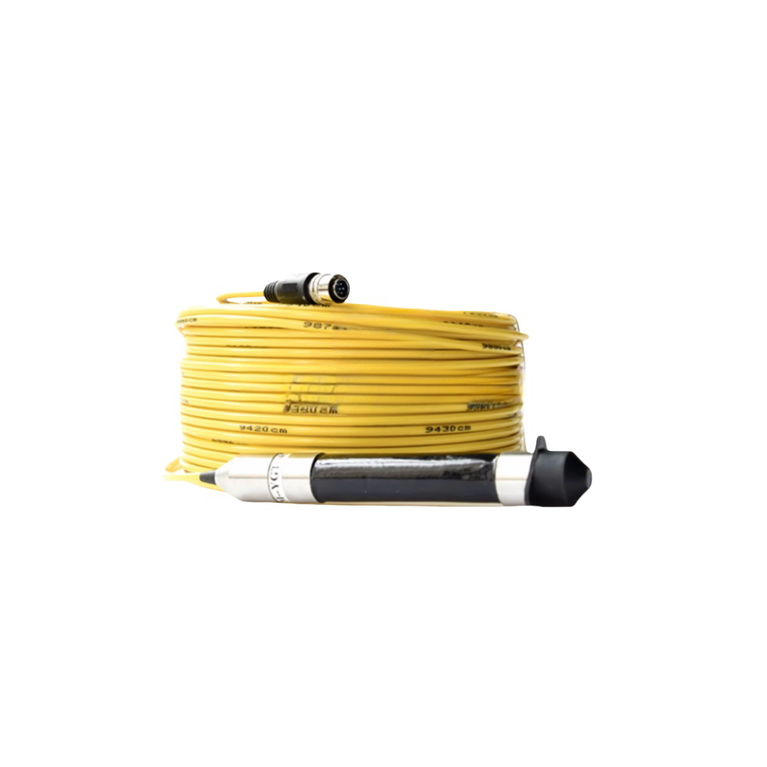
The RST-KFC Series Kevlar-Reinforced Fiber Optic Cable delivers high tensile strength for subsea, aerial, and industrial fiber runs where steel armoring is excluded by weight, magnetic signature, or galvanic corrosion risk. Kevlar 49 counter-wound torque-balanced construction achieves ≤0.5°/m self-rotation at rated load, SM G.657.A1 fiber in gel-filled loose tubes, depth-rated to 3,000 m, tensile ratings 0.5–12 kN, every drum load-tested and OTDR-traced. |
Kevlar-Reinforced Fiber Optic Cable | High Tensile Strength Armored Fiber for Subsea & Industrial Use
Product Series: RST-KFC │ Category: High-Tensile Armored Fiber Optic Cables │ Reviewed by: Rousheng Fiber Engineering Team
|
Why Kevlar, not steel wire? 5× stronger than steel at equal mass Non-conductive — no galvanic risk in seawater No magnetic signature — critical for naval MCM Torque-balanced construction eliminates self-rotation Lighter than steel: enables longer unsupported spans Available in 0.5 kN – 12 kN ratings per model |
RST-KFC at a glance Fibre: SM G.657.A1 or MM OM4, 1–48 fibres Depth: to 3,000 m (gel-fill + pressure-tested) Tensile: 0.5–12 kN, load-tested to 1.5× per drum OD: 6.5–22 mm depending on configuration Jacket: polyether PUR, 5,000 h seawater immersion tested OTDR trace + tensile certificate per drum |
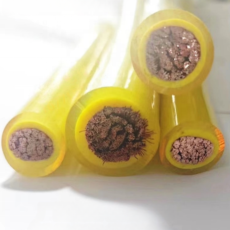
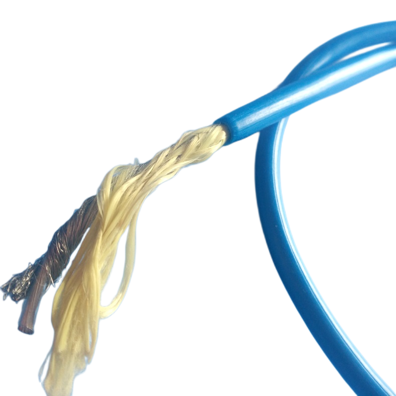
Kevlar-reinforced fiber optic cable occupies a specific performance envelope that neither bare fiber cable nor steel-armored cable can fill: applications that require substantial tensile strength — enough to support long unsupported cable spans, withstand towing loads, or survive rough handling — but where steel armoring is excluded by weight, magnetic signature, galvanic corrosion, or installation constraints. The aramid fiber (Kevlar) tensile member achieves a strength-to-weight ratio approximately five times that of steel wire, making it the enabling technology for lightweight deep-sea ROV tethers, aerial fiber runs to offshore structures, and military MCM umbilicals where a zero magnetic signature is operationally mandatory.
The RST-KFC series is engineered around Kevlar 49 high-modulus aramid in a counter-wound torque-balanced configuration — the geometry that prevents cable self-rotation under tensile load, a failure mode that defeats sensor platforms and ROV navigation systems alike. Every RST-KFC drum is load-tested to 1.5× its rated tensile capacity before the fibre is installed, ensuring that the structural element is verified before the optical elements are committed.
▶ Tensile Material Selection — Why Kevlar 49, and When to Choose Alternatives
Four materials are specified as tensile members in high-performance fiber optic cables. Understanding the mechanical trade-offs between them is the foundation of correct cable selection for subsea, aerial, and industrial applications.
|
Property |
Kevlar 29 |
Kevlar 49 |
Vectran HS |
304 SS Wire |
|
Tensile strength (GPa) |
2.9 |
3.6 |
3.2 |
0.9 (304 annealed) |
|
Young’s modulus (GPa) |
70 |
125 |
103 |
193 |
|
Elongation at break (%) |
3.5 |
2.4 |
3.3 |
40 |
|
Density (g/cm³) |
1.44 |
1.44 |
1.41 |
7.90 |
|
Strength-to-weight ratio |
2.0 GPa·cm³/g |
2.5 |
2.3 |
0.11 |
|
Torque balance achievable |
Yes |
Yes |
Yes |
With contra-wound layers |
|
Magnetic signature |
None |
None |
None |
Ferromagnetic if not SS |
|
Galvanic risk in seawater |
None |
None |
None |
High (unless 316L SS) |
|
UV resistance |
Poor — needs UV jacket |
Poor |
Good |
Excellent |
|
Creep under sustained load |
Low |
Very low |
Very low |
Negligible |
|
RST-KFC application |
Dynamic flex, ROV |
Deep tow, survey, industrial |
High modulus alternative |
Not used (RST-FOC-A series) |
|
RST-KFC default: Kevlar 49. High modulus (125 GPa) limits elongation at rated load to ≤1.5%, preserving cable length accuracy in towed sensor arrays and preventing fibre strain from conductor elongation under sustained tensile load. Kevlar 29 (lower modulus, higher elongation) is used only in floating surface cables (RST-FFC series) where elastic energy absorption under wave impact is prioritised over length accuracy. If your application requires elongation <2% at rated load, specify Kevlar 49 — which is the RST-KFC standard. |
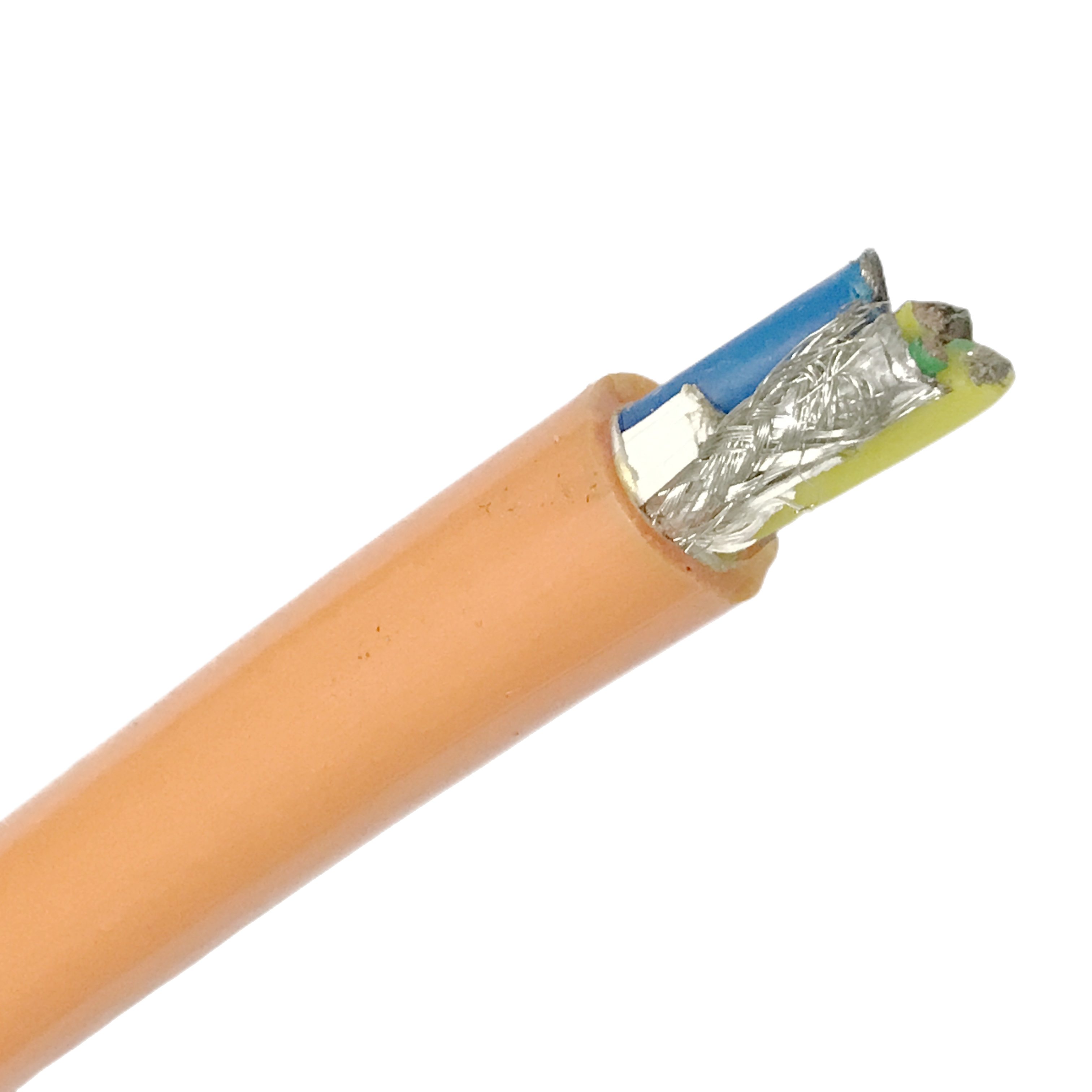
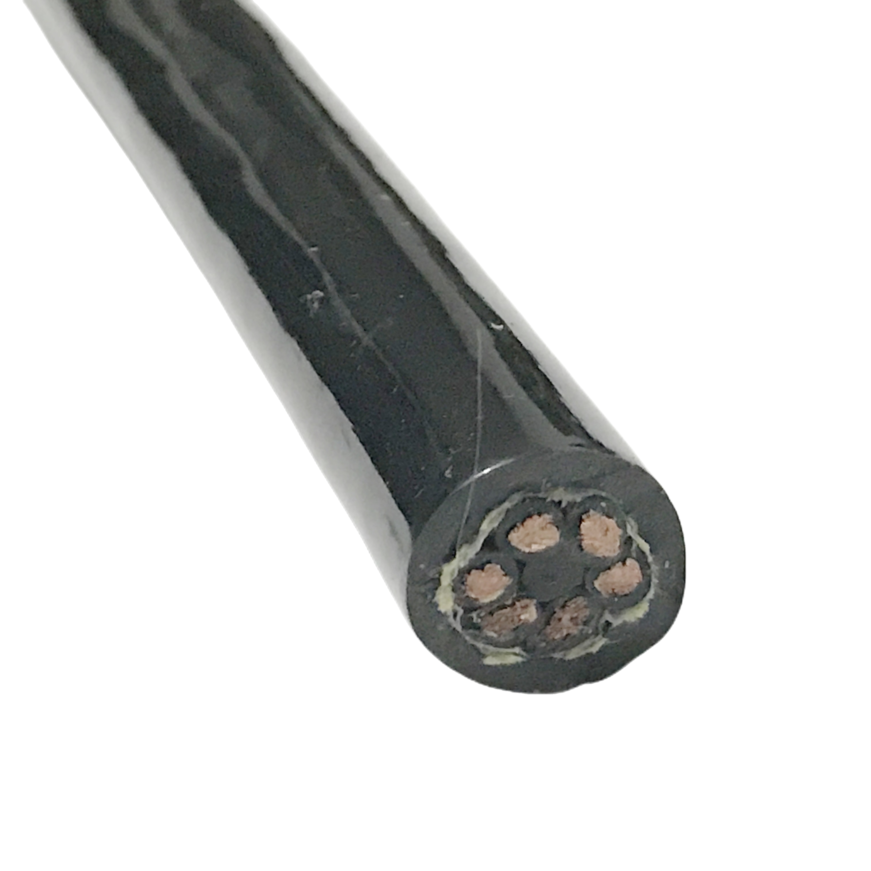
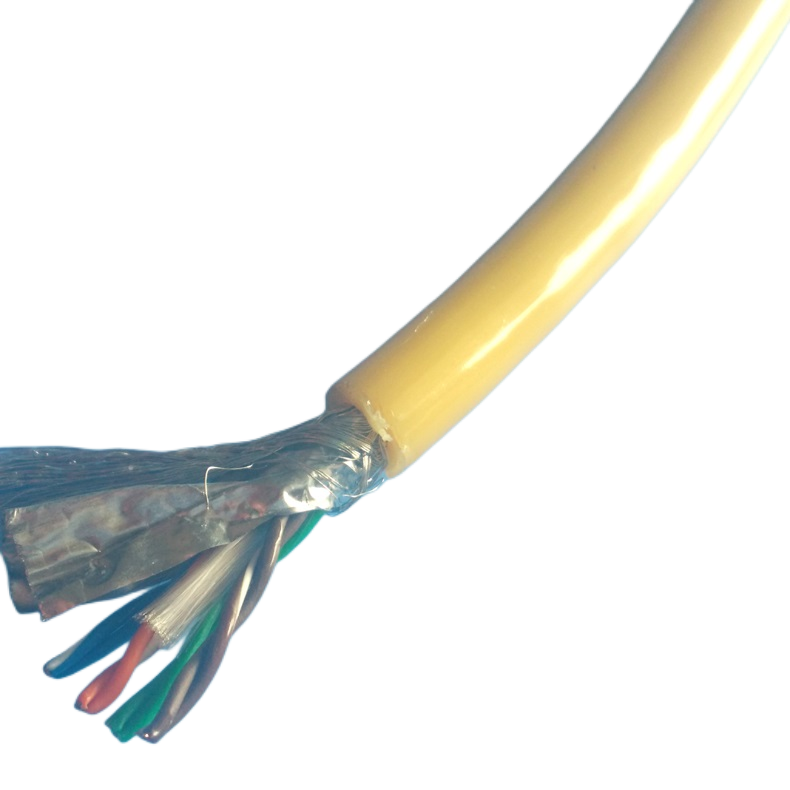
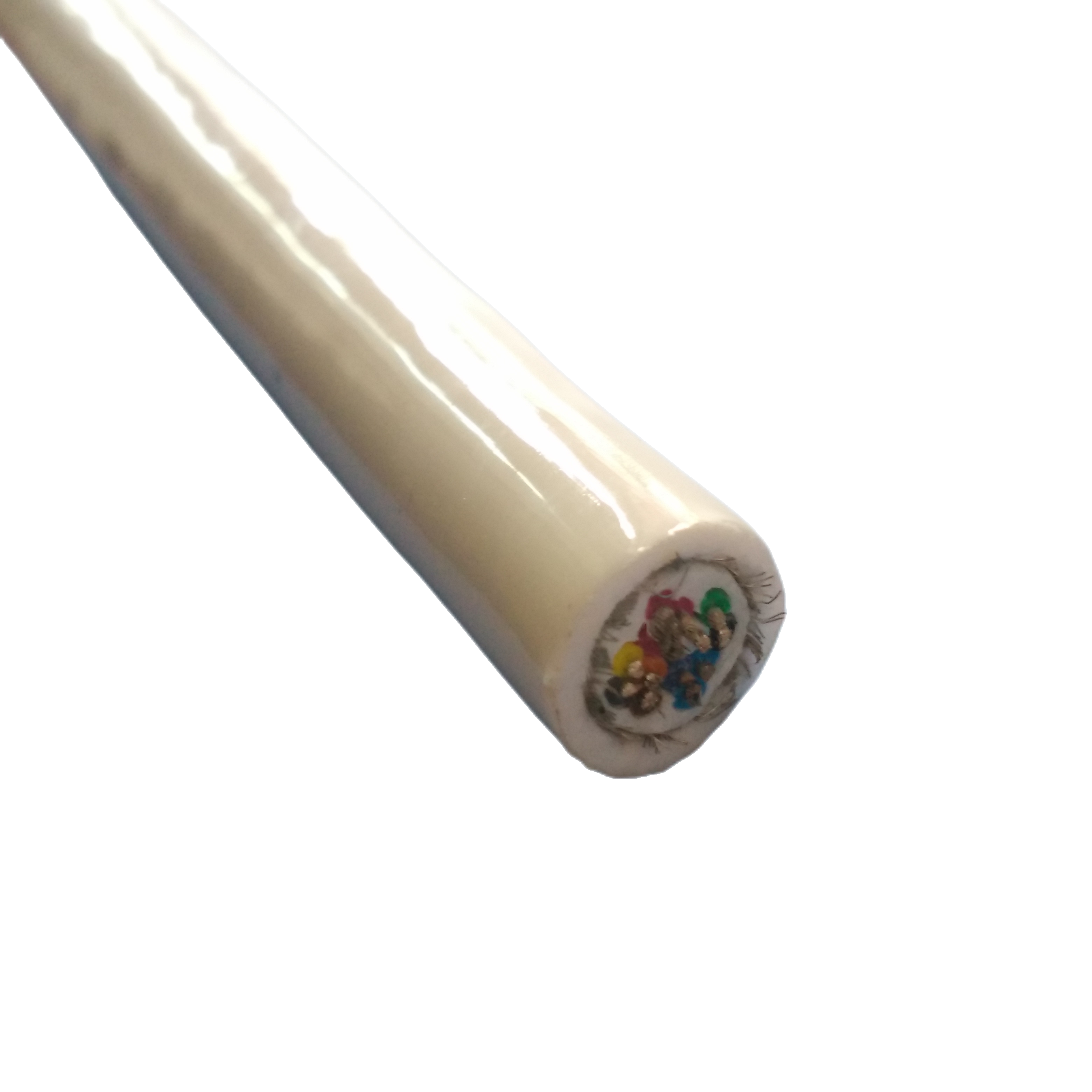
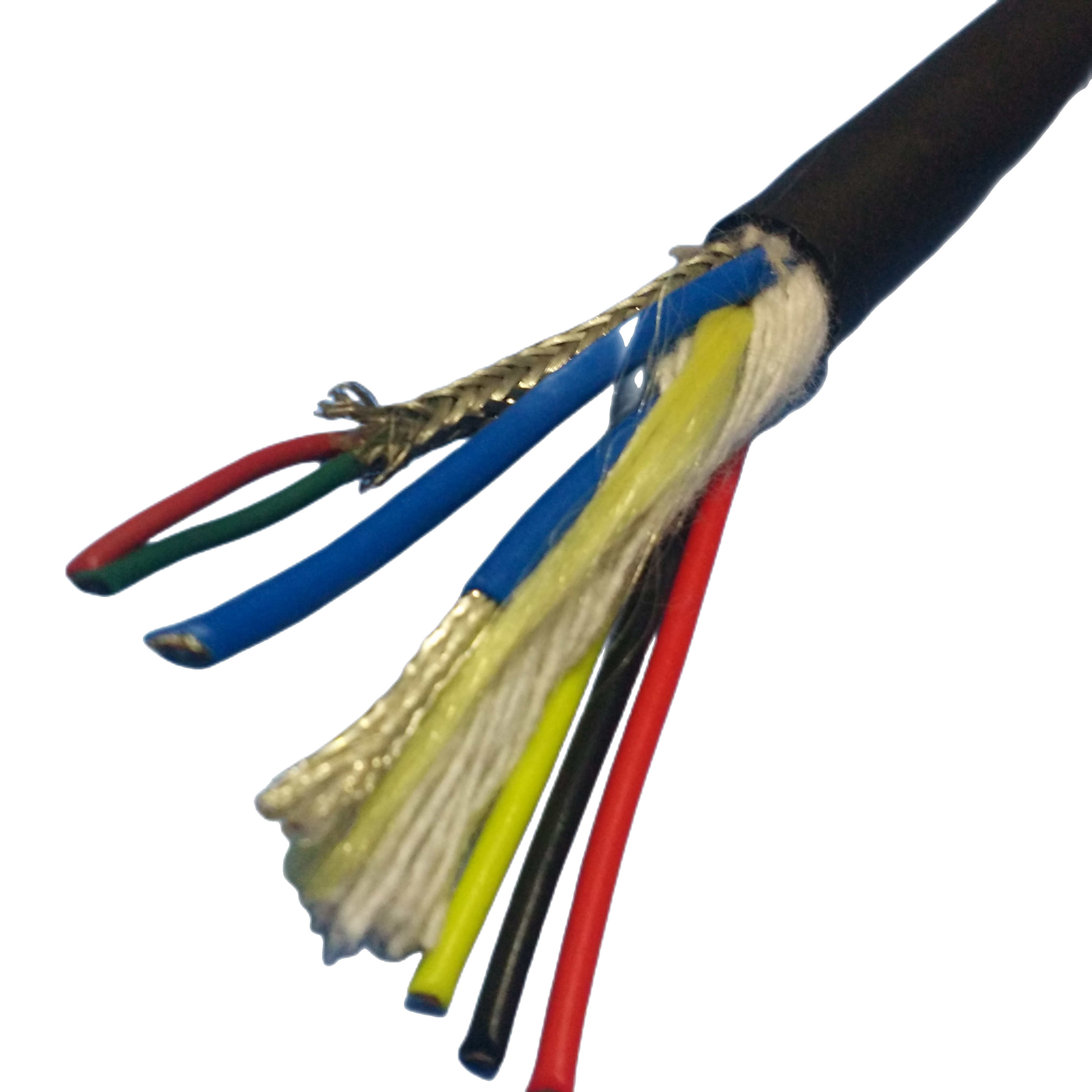
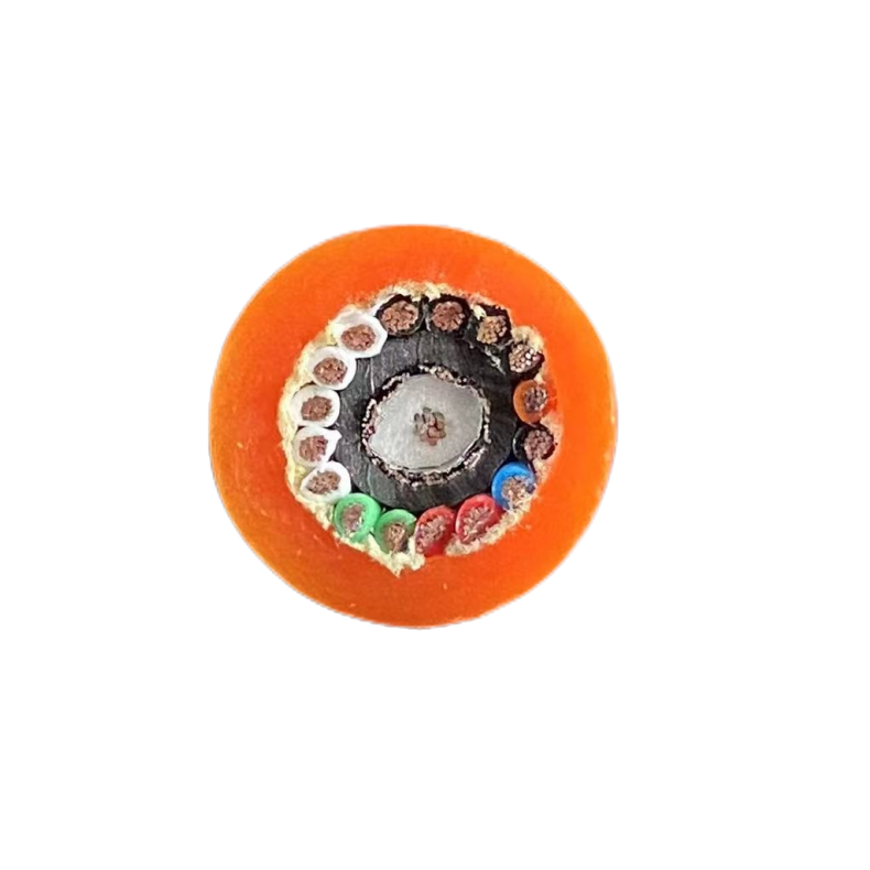
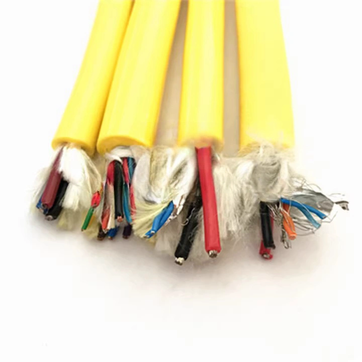
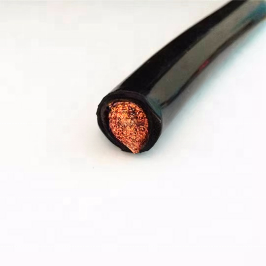
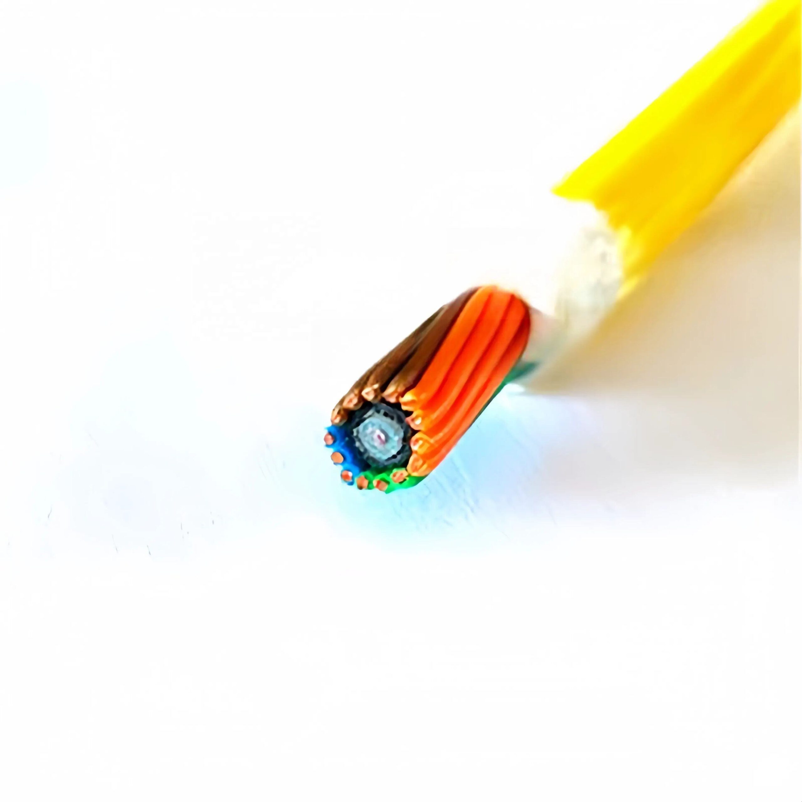
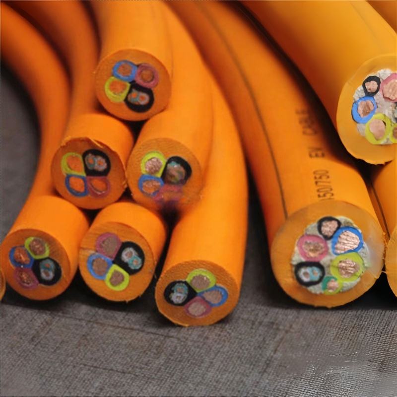
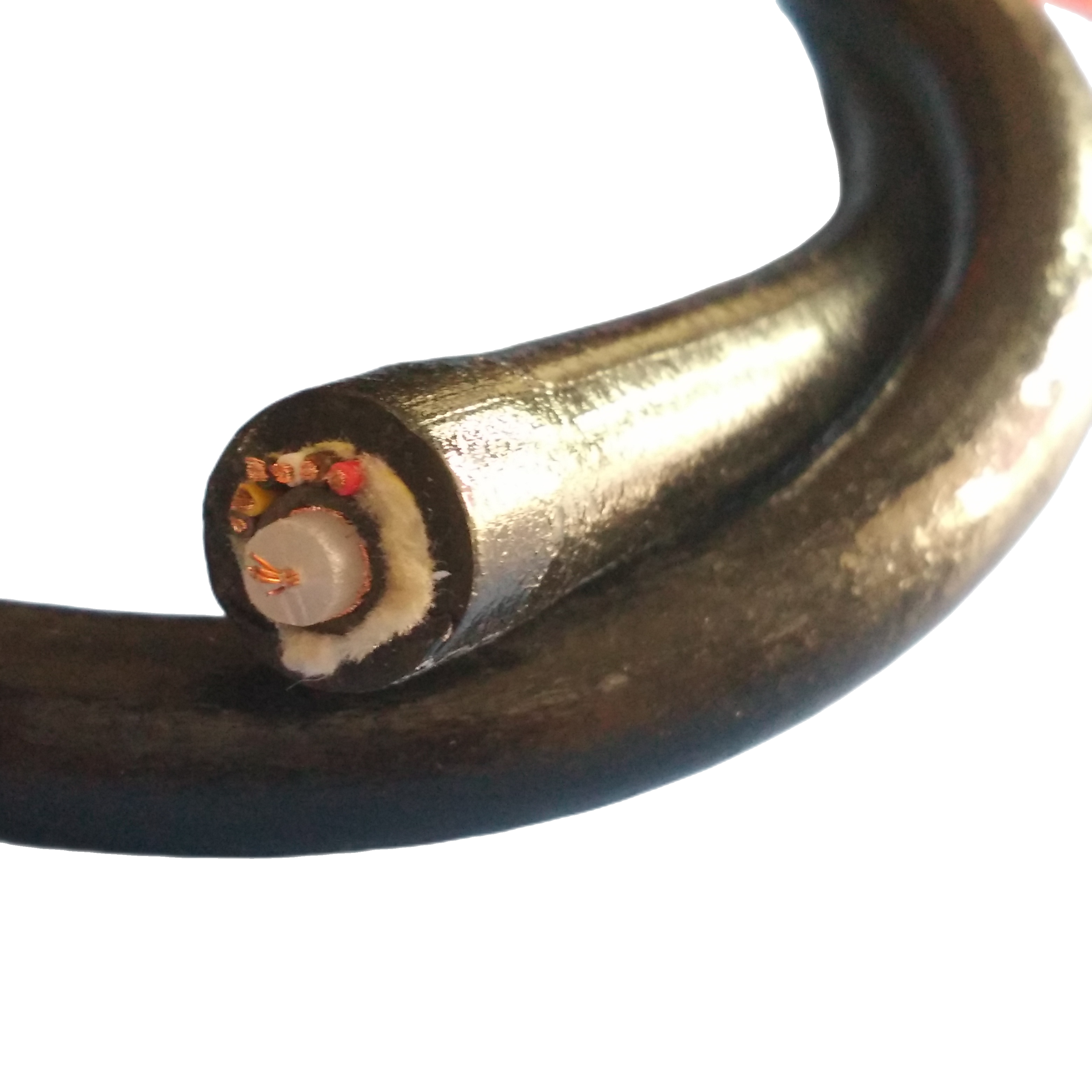
▶ Cross-Section Anatomy — Reading the RST-KFC Structure
The RST-KFC cross-section is read from outside to centre. Each layer is indented relative to the layer outside it, mirroring the physical nesting of the cable construction.
|
Layer 5: Outer jacket — polyether PUR Shore A 82±3 | Tensile ≥48 MPa | Taber ≥350 cycles | 5,000 h seawater immersion tested |
|
Layer 4: Kevlar 49 tensile member — counter-wound two layers Equal & opposite helix angles | Torque-balanced | 0.5–12 kN rated | load-tested 1.5× |
|
Layer 3: Water-blocking barrier — SAP tape + gel fill SAP absorption ≥400× | Migration ≤0.5 m from breach | IEC 60794-1-2 F5B |
|
Layer 2: Core assembly — loose tube bundle PBT tubes, gel-filled | Fibre at neutral axis | Polyester fleece binder |
|
Layer 1: Optical fibre — SM G.657.A1 or MM OM4 ≤0.20 dB/km @ 1,550 nm | Loose in gel tube | <0.08 dB/km additional at 1.5× rated depth |
Each RST-KFC cable positions the optical fibre bundle at the geometric centre (neutral axis) of the cross-section — the zone of minimum bending strain in any dynamic application. The Kevlar tensile member surrounds the optical core, carrying tensile load in a layer that never contacts the fibre elements directly.
▶ RST-KFC Series — Model Reference
|
Model |
Fibre |
Count |
Kevlar Rating |
OD |
Depth |
Elongation @ Load |
Key Application |
|
RST-KFC-1-2SM |
SM G.657.A1 |
2 |
0.5 kN |
6.5 mm |
200 m |
≤1.5% |
Drone tether, light aerial span |
|
RST-KFC-2-4SM |
SM G.657.A1 |
4 |
1.0 kN |
8.8 mm |
500 m |
≤1.5% |
ROV inspection umbilical, buoy link |
|
RST-KFC-3-4SM |
SM G.657.A1 |
4 |
2.0 kN |
10.4 mm |
1,000 m |
≤1.5% |
Work-class ROV, offshore sensor |
|
RST-KFC-4-8SM |
SM G.657.A1 |
8 |
3.0 kN |
13.2 mm |
1,500 m |
≤1.5% |
Deep ROV, towed instrument |
|
RST-KFC-5-12SM |
SM G.657.A1 |
12 |
5.0 kN |
16.0 mm |
2,000 m |
≤1.5% |
Survey array, mooring backbone |
|
RST-KFC-6-24SM |
SM G.657.A1 |
24 |
8.0 kN |
20.5 mm |
3,000 m |
≤1.5% |
Deep survey, oceanographic tow |
|
RST-KFC-7-48SM |
SM G.657.A1 |
48 |
12.0 kN |
26.8 mm |
3,000 m |
≤1.5% |
Dense array, research backbone |
|
RST-KFC-MM-4 |
MM OM4 |
4 |
1.5 kN |
9.6 mm |
200 m |
≤1.5% |
Short aerial span, industrial flex |
|
RST-KFC-HB-4SM |
SM G.657.A1 + 2×1.5 mm² power |
4+power |
2.5 kN |
14.0 mm |
500 m |
≤1.5% |
Powered ROV, sensor with supply |
|
RST-KFC-OEM |
Custom SM/MM |
1–48 |
0.5–12 kN |
Per spec |
Per spec |
≤1.5% |
Naval, offshore, industrial custom |
All models: Kevlar 49 counter-wound torque-balanced | Gel-filled loose tube | Polyether PUR jacket | Pressure-tested at 1.5× rated depth | OTDR trace + load certificate per drum. HB = hybrid (fiber + power). OEM: specify fibre count, Kevlar rating, depth, and hybrid requirement.
▶ Tensile Sizing Guide — Safety Factor Selection by Application
Tensile member selection is not simply ‘pick the closest rating above expected load’. Each application type has an industry-accepted minimum safety factor (SF = tensile rating ÷ peak operating load) that accounts for dynamic load amplification, fatigue, and the consequence of failure. The table below maps common RST-KFC applications to the correct SF and resulting minimum cable rating.
|
Application |
Peak Cable Load |
Required SF |
Min Tensile Rating |
RST-KFC Model |
|
Static hanging (mooring, fixed vertical drop) |
Cable dead weight + 20% dynamic |
SF ≥2.0 |
= (dead load × 1.2) × 2.0 |
RST-KFC-2 to RST-KFC-5 per calculation |
|
ROV umbilical (thruster-assisted, ROV neutrally buoyant) |
Cable catenary weight + ROV emergency pull-out force |
SF ≥3.0 |
= (catenary load + pull-out) × 3.0 |
RST-KFC-3 or RST-KFC-4 typical |
|
Towed survey cable (vessel tow, <3 kts) |
Hydrodynamic drag at max tow speed |
SF ≥3.5 (IOC guideline for scientific tow) |
= drag load × 3.5 |
RST-KFC-5 or RST-KFC-6 per catenary model |
|
Aerial span (structure to structure, outdoor) |
Cable dead weight + ice load + wind load (per EN 50182) |
SF ≥5.0 (EN 50182 aerial guideline) |
= (gravity + ice + wind) × 5.0 |
RST-KFC-3 or RST-KFC-4 typical spans <100 m |
|
Naval MCM (rapid deployment, impulsive loads) |
Max deployment speed tension + safety margin |
SF ≥5.0 (naval MIL-spec guidance) |
= (deployment tension) × 5.0 |
RST-KFC-4 or RST-KFC-5 per scenario |
|
Industrial drag track (moving machinery, cyclic load) |
Peak drag load at rated speed + acceleration spike |
SF ≥4.0 (IEC 62440 guidance for cable carriers) |
= (drag + acceleration spike) × 4.0 |
RST-KFC-2 or RST-KFC-3 typical |
|
Rescue / emergency retrieval tether |
Human body + equipment weight + 3× dynamic impact |
SF ≥10.0 (life-safety) |
= total load × 10.0 (life-critical applications) |
RST-KFC-4 minimum (2.0 kN × 10 SF = 20 kN: consult engineering) |
|
Worked example — ROV umbilical, 800 m depth: Cable mass in water: 0.08 kg/m × 800 m = 64 kg = 0.63 kN dead load. Emergency pull-out force (stuck ROV): estimated 0.5 kN. Total peak load: 1.13 kN. SF = 3.0 → required tensile rating: 1.13 × 3.0 = 3.4 kN. Selection: RST-KFC-4-8SM (3.0 kN) is slightly below; select RST-KFC-5-12SM (5.0 kN) for SF = 4.4 — acceptable for a depth-rated ROV umbilical with no onboard buoyancy. If ROV is positively buoyant, recalculate with reduced cable catenary weight. |
▶ Application Matrix — What Kevlar Reinforcement Provides in Each Context
|
Application |
Tensile Load Source |
Why Kevlar vs Steel Armour |
Typical Model |
Critical Spec |
|
Deep-sea ROV umbilical |
Catenary weight of hanging cable at depth |
Steel armour too heavy; adds negative buoyancy that overloads ROV thrusters. Kevlar at equal strength weighs 5.5× less per unit length in air. |
RST-KFC-3 to RST-KFC-5 |
Elongation ≤1.5% at rated load (prevents fibre strain) |
|
Towed acoustic array (hydrophone streamer) |
Hydrodynamic drag at tow speed, catenary angle |
Steel armour causes cable self-rotation, destroying hydrophone calibration geometry. Kevlar torque-balanced ≤0.5°/m. |
RST-KFC-5-12SM or RST-KFC-6-24SM |
Torque-balanced; self-rotation ≤0.5°/m at rated load |
|
Naval mine countermeasures (MCM) umbilical |
Deployment and recovery forces from MCM vessel |
Steel armour creates magnetic signature detectable by mine fuzes. Kevlar is non-magnetic. |
RST-KFC-4-8SM (custom non-magnetic jacket) |
Zero magnetic signature; all-dielectric construction |
|
Aerial fiber span, offshore platform |
Dead weight of cable span + wind + ice |
Weight is critical: lighter Kevlar cable reduces sag and termination load on platform structure. Non-conductive: no lightning path. |
RST-KFC-3-4SM or RST-KFC-4-8SM |
SF ≥5.0 per EN 50182; non-conductive tensile member |
|
Subsea observatory mooring |
Mooring tension from ocean current drag on instruments |
Kevlar all-dielectric; no galvanic corrosion in multi-year unattended deployment. Steel armour corrodes without maintenance. |
RST-KFC-5-12SM or RST-KFC-6-24SM |
Galvanic inertness; 5-year+ unattended service life |
|
Industrial overhead crane camera |
Dead weight of cable + dynamic load from crane acceleration |
Kevlar provides high SF in a small OD cable that fits within the cable management channels of the crane structure. |
RST-KFC-2-4SM |
OD ≤9 mm for standard crane cable channels; SF ≥5.0 |
|
Offshore wind turbine blade inspection |
Wind loading on cable paid out from inspection UAV/drone |
Non-conductive: safe for deployment from a drone in proximity to live HV cables. Lightweight: extends drone flight time. |
RST-KFC-1-2SM |
Mass per metre ≤30 g/m; non-conductive all-dielectric |
|
Seismic survey streamer lead-in |
Tow drag from seismic vessel at 4–5 knots |
Torque balance essential: streamer array geometry depends on zero cable rotation. Non-magnetic for towed magnetometer surveys. |
RST-KFC-6-24SM |
Torque balance; ≤0.5°/m; rated to 8 kN for 3.5 SF at 4 knots |
▶ Torque Balance — The Engineering Mechanism
Torque balance is specified in every RST-KFC model, but the mechanism is rarely explained in cable data sheets. Understanding it matters because it is the property that differentiates a Kevlar-reinforced cable from a steel-armored cable in sensor and navigation applications.
Why unbalanced cables self-rotate
Any helical tensile element — whether a single-layer Kevlar braid or a helical steel wire — converts axial tension into a torsional moment. The physics: tension in a helix of pitch angle θ produces a torsional moment M = T × r × sin(θ) × cos(θ), where T is tension, r is helix radius, and θ is the helix angle. A cable free to rotate at one end will rotate until this moment is reduced to zero by coiling — which is exactly what happens to an unbalanced ROV umbilical or towed array lead-in.
How counter-winding achieves balance
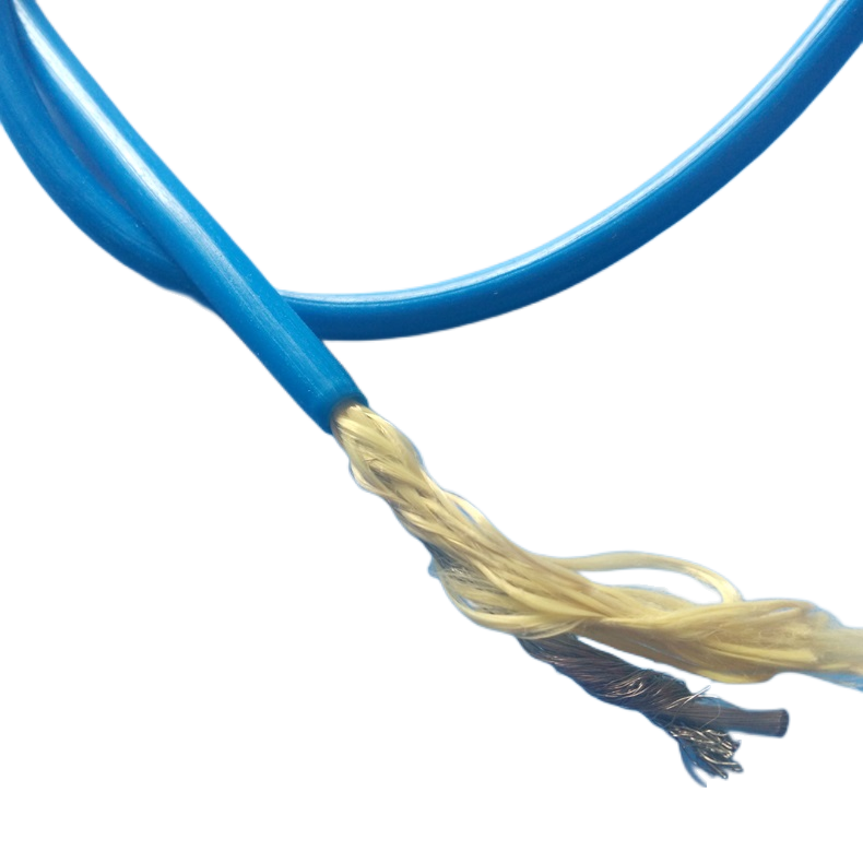
RST-KFC uses two Kevlar yarn layers wound at the same absolute helix angle but in opposite directions — one layer has a right-hand lay, the other a left-hand lay. If both layers have the same yarn count, the same helix radius, and the same helix angle, the torsional moments from the two layers are equal and opposite, summing to zero net torque. The cable does not rotate under any tensile load within its rated capacity.
|
Measured performance: RST-KFC torque balance validation is performed on a 10 m free-hanging sample with the top end fixed and a calibrated load cell at the bottom. At 100% of rated tensile load, rotation is measured at the bottom end. RST-KFC specification: ≤0.5°/m — equivalent to 5° rotation over a 10 m free length at full rated load. This is the threshold below which hydrophone calibration geometry and AUV INS accuracy are unaffected by cable self-rotation in published field experience from oceanographic institutions. Test data on request: Torque rotation test data for the specific drum and Kevlar lay configuration is available on request for qualification purposes. Specify ‘torque balance test data required’ when placing your order or submitting an RFQ. |
When torque balance is not needed
Torque balance adds approximately 10–15% to cable cost because it requires two Kevlar winding passes at identical helix geometry. For applications where the cable is restrained against rotation at both ends — such as a fixed vertical mooring or a cable pulled through conduit — torque balance provides no operational benefit. Specify the single-layer Kevlar variant (RST-KFC-SL suffix) to reduce cost for these applications. Contact our engineering team to confirm whether your installation geometry prevents cable rotation.
▶ Technical Parameters
Optical — SM G.657.A1
|
Parameter |
Specification |
Standard |
|
Attenuation @ 1,310 nm |
≤0.36 dB/km |
IEC 60793-2-50 |
|
Attenuation @ 1,550 nm |
≤0.20 dB/km |
IEC 60793-2-50 |
|
Additional attenuation at 1.5× rated depth |
≤0.08 dB/km |
IEC 60794-1-2 F12B |
|
Additional attenuation: 1,000 bending cycles at 10× OD |
≤0.03 dB/km |
IEC 60794-1-2 E10 |
|
PMD |
≤0.04 ps/√km |
IEC 60793-2-50 |
|
Min bend radius (G.657.A1, long-term) |
≥10 mm |
IEC 60793-2-50 |
|
OTDR trace supplied |
.SOR + PDF; 1,310 + 1,550 nm; per fibre per drum |
Factory measurement |
Mechanical
|
Parameter |
Value |
Reference / Test |
|
Tensile member |
Kevlar 49 aramid, counter-wound, torque-balanced |
— |
|
Kevlar tensile rating |
0.5 kN – 12 kN per model |
— |
|
Proof load (per drum) |
1.5× rated tensile load; load-cell certified |
ASTM D7269 |
|
Self-rotation |
≤0.5°/m at rated load (torque-balanced models) |
Internal 10 m hanging test |
|
Elongation at rated load |
≤1.5% (Kevlar 49) |
ISO 6892 |
|
Creep (sustained load) |
<0.05% additional elongation after 24 h at 50% rated load |
Internal test |
|
Min bending radius (dynamic) |
10× OD |
IEC 60794-1-2 E10 |
|
Min bending radius (static) |
5× OD |
— |
|
Working depth (per model) |
200 m – 3,000 m |
Pressure-tested at 1.5×; IEC 60794-1-2 F12B |
|
Crush resistance |
≥100 N/cm without permanent attenuation change |
IEC 60794-1-2 E3 |
|
Impact resistance |
≥5 J, no fibre break |
IEC 60794-1-2 E4 |
|
Torsion (±180°/m, 2 m gauge) |
No fibre break; ≤0.05 dB/km attenuation change |
IEC 60794-1-2 E7 |
Environmental
|
Parameter |
Value |
Standard |
|
Jacket material |
Polyether TPU, Shore A 82±3 |
ISO 868 |
|
Jacket tensile strength |
≥48 MPa |
ISO 37 |
|
Jacket elongation |
≥380% |
ISO 37 |
|
Jacket abrasion |
≥350 cycles Taber CS-17 1 kg |
ISO 9352 |
|
Seawater hydrolysis |
<1% tensile change after 5,000 h at 23°C |
ISO 175 |
|
Operating temperature |
−40°C to +70°C (surface); 0°C–4°C (seabed) |
IEC 60811-501 |
|
UV resistance (standard) |
1,000 h xenon arc; ≤80% tensile retention |
IEC 60811-401 |
|
Longitudinal watertightness |
≤0.5 m migration from breach |
IEC 60794-1-2 F5B |
|
Electrical conductivity |
All-dielectric — zero conductivity (no metal elements) |
— |
|
Magnetic signature |
None (all-dielectric construction) |
MIL-DTL-24643 guidance |
▶ Project References
Customer identities withheld. Technical data verified and available under NDA for qualified organisations.
|
Project |
System |
Model |
Technical Challenge |
Result |
|
European Navy, MCM programme |
Sonar deployment umbilical, 300 m, mine countermeasures AUV, zero magnetic signature required |
RST-KFC-4-8SM custom, all-dielectric, non-magnetic jacket compound |
Standard cable with SS armour failed MCM magnetic signature test at 1 m standoff. RST-KFC-4-8SM Kevlar-only construction passed at 0.05 m standoff. Torque balance measured: 0.18°/m at 2.0 kN — within specification. |
Adopted as programme-standard umbilical. 18 units supplied 2023. |
|
Seismic contractor, Atlantic survey |
Streamer lead-in section, 24 fibres, 1,800 m, 4-knot tow |
RST-KFC-6-24SM, 8.0 kN Kevlar, torque-balanced |
Previous single-layer Kevlar cable rotated at 2.1°/m at 4 knots tow tension, distorting hydrophone array geometry by 3.8 m at 1,800 m range. RST-KFC torque balance: 0.42°/m — array distortion reduced to 0.76 m, within navigation tolerance. |
Full season completed 2023. Array geometry within spec throughout. |
|
Offshore wind O&M, North Sea |
Turbine inspection drone fiber tether, 150 m, blade inspection in live HV environment |
RST-KFC-1-2SM, 0.5 kN Kevlar, all-dielectric, 20 g/m |
Conductive steel-armored tether created safety exclusion zone of 5 m around any HV cable. All-dielectric RST-KFC-1-2SM cleared for operation within 0.5 m of live cables under DNV risk assessment. |
Inspection programme completed. 40% reduction in inspection time vs previous tethered drone. |
|
Oceanographic institution, Pacific mooring |
3-year unattended mooring, 12 instruments, 2,400 m depth, 24 fibres |
RST-KFC-6-24SM, 8.0 kN, galvanic-inert all-dielectric |
Previous steel-armored cable required zinc anode replacement every 18 months for corrosion protection, impossible on an unattended mooring. RST-KFC all-dielectric construction requires zero corrosion maintenance. |
Year 2 of 3-year deployment. Annual OTDR check: 0.22 dB/km @ 1,550 nm, stable. |
|
Industrial automation, automotive plant |
Overhead crane camera system, 15 m aerial span between crane bridge and fixed structure |
RST-KFC-2-4SM, 1.0 kN Kevlar |
Steel messenger wire previously used for camera cable support induced EMI artifacts in camera signal at 50 Hz from crane motor drive. All-dielectric Kevlar eliminated the conductive path; EMI artifacts removed without filtering. |
12 crane cameras upgraded. Zero signal interference reported since installation 2022. |
▶ FAQ — Engineers & System Integrators
Q1: How do I terminate the Kevlar tensile member at each end of the cable?
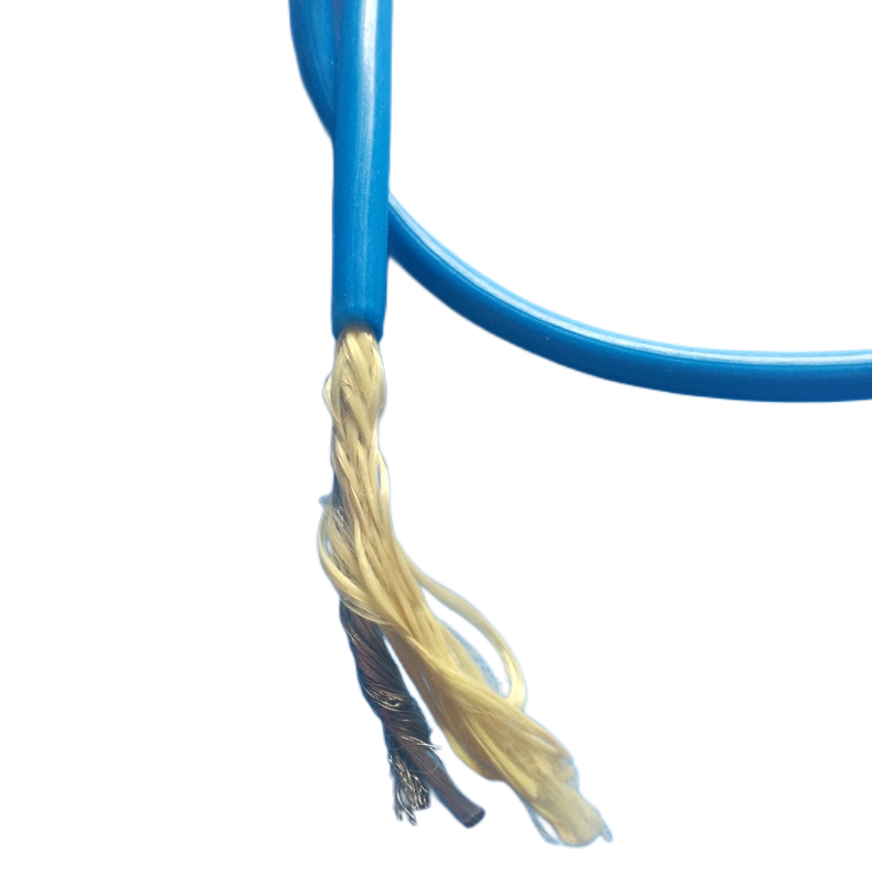
Kevlar cannot be clamped by crimping in the same way as steel wire — crimping compresses the yarn bundle and reduces tensile strength at the termination by up to 40%. The correct termination methods for Kevlar in fiber optic cable are: (1) Resin potting: the Kevlar yarn end is fanned out in a conical steel or aluminium pot and filled with low-shrink epoxy resin. Pull-out strength from a correctly potted termination is >90% of yarn rated strength. This is the standard method for RST-KFC factory terminations. (2) Woven pulling grip (Kellems grip): a braided metal sleeve is pulled over the Kevlar and cable jacket, and a wedge action locks the grip under tension. This method is used for field-installed mid-run tensile grips and for temporary installations. (3) Braided aramid spliced knot: for very light loads (<200 N), a simple double-fisherman’s knot in the yarn bundle is acceptable. Provide your termination hardware details when ordering — RST-KFC factory-terminated cables are available with potted termination ends installed.
Q2: Does Kevlar degrade in seawater over time?
Kevlar 49 (poly-para-phenylene terephthalamide) is resistant to seawater immersion but has two known degradation mechanisms that must be managed. First, UV sensitivity: Kevlar loses strength rapidly under direct UV exposure. In RST-KFC, the Kevlar is enclosed inside the outer jacket and is never directly exposed to UV — this is a non-issue in the cable as supplied. Second, hydrolytic degradation under sustained tension at elevated temperature: Kevlar in constant tension in hot water (>40°C) can hydrolyse slowly over years. At seabed temperatures of 2–4°C, this degradation rate is negligible. At tropical surface temperatures (30°C+) with sustained load, degradation should be assessed for deployments exceeding 5 years. Rousheng can provide accelerated aging test data for specific temperature and load profiles on request.
Q3: What is the minimum bend radius for a Kevlar-reinforced cable, and what happens if it is exceeded?
The minimum bend radius for RST-KFC cables is 10× OD for dynamic applications and 5× OD for static installation. The minimum is set by the Kevlar, not the fibre: G.657.A1 fibre can tolerate bends as tight as 7.5 mm radius, but Kevlar yarn bent below a critical radius begins to develop kink deformation in individual yarn filaments, reducing tensile strength locally. A Kevlar cable bent once below its minimum radius may show no immediate optical performance change but has reduced tensile capacity at the kink point. After installation, inspect any point where the cable has contacted a sharp edge, pipe, or structure — if the cable shows a permanent kink (a deviation that does not relax when tension is removed), the tensile capacity at that point is compromised and the cable section should be replaced.
Q4: Can RST-KFC cables be coiled on a drum reel for long-term storage?
Yes. RST-KFC cables are supplied on wooden or steel shipping drums with core diameters that satisfy the minimum bend radius requirement. For long-term storage (>6 months), store drums horizontally (drum axis vertical) in a dry, dark environment below 30°C and away from ozone sources. Kevlar is not damaged by prolonged storage under its own weight; however, do not stack heavy objects on a drum that compresses the cable — the outer layer experiences sustained compression that can cause the gel fill to migrate from the fibre tube interstices over time, reducing longitudinal water-blocking effectiveness. A drum stored correctly for 5+ years and inspected to confirm jacket integrity can be deployed without loss of mechanical or optical performance.
Q5: Is RST-KFC compatible with standard fiber optic cable termination tools and fusion splicers?
Yes. The optical fibre elements in RST-KFC are standard G.657.A1 or OM4 fibres in PBT loose tubes — identical to the fibre elements in any terrestrial or standard subsea fiber cable. They can be fusion-spliced with any standard fusion splicer (Fujikura, Sumitomo, INNO, etc.) using normal splicing parameters for G.657.A1 (same as G.652.D). The Kevlar yarn layer must be cut and the jacket stripped before accessing the fibre tubes; a cable-jacket stripper tool and Kevlar shears (standard in any fiber termination kit) are required. RST-KFC cables are available factory-terminated with fusion-spliced pigtails on request — specify the connector type (FC/APC, SC/APC, LC/APC) and pigtail length at order.
▶ Manufacturer Background — Shanghai Rousheng
|
Kevlar cable capabilities Dedicated Kevlar 49 winding line: dual contra-wound layers, helix angle calibrated to ±0.5° Per-drum torque balance validation: 10 m hanging test with calibrated load cell Per-drum tensile proof load to 1.5× rated: load-cell certificate included Hyperbaric test chamber to 600 bar for depth-rated models 100% OTDR trace: 1,310 + 1,550 nm per fibre per drum, .SOR archive Factory potted Kevlar termination service (resin-pot method) |
Certifications ISO 9001:2015 quality management CE marking — LVD Directive 2014/35/EU RoHS 2 / REACH SVHC compliance DNV / Bureau Veritas type approval on request MIL-DTL-24643 all-dielectric compliance guidance (naval) CNAS-accredited third-party lab reports on request |
▶ Request a Quote or Engineering Review
|
Contact Email: Jerry@rstlkable.com Phone: +86-021-50759965 Mobile: +86-13482197396 Address: No. 2591 Fengzhe Road, Fengxian District, Shanghai, China Quote within 24 hours. OTDR trace, torque balance test data, and tensile load certificate included per drum. |
Include in your enquiry 1. Application type (ROV, towed array, aerial, mooring, etc.) 2. Peak tensile load estimate (N or kN) and safety factor required 3. Depth rating required (m) and deployment duration 4. Fibre count and type (SM, MM, or hybrid with power) 5. Magnetic signature requirement (yes/no) 6. Torque balance requirement (yes/no) We return a tensile member calculation, SF analysis, model recommendation, and OD/mass estimate with every technical enquiry. |