High-Performance Servo Motor Cable | Shielded Flexible Cable for Precision Motion Control
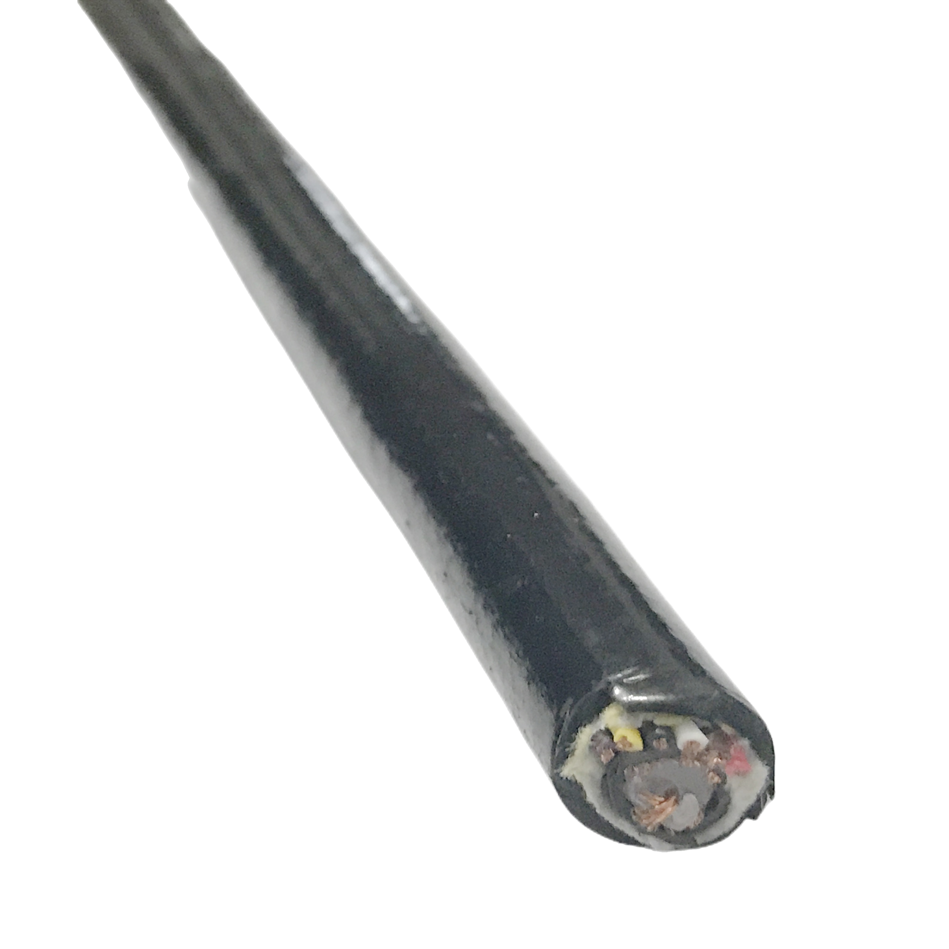
The RST-SMC Series Servo Motor Cable integrates motor power and encoder signals in a single high-performance solution for servo drive systems.
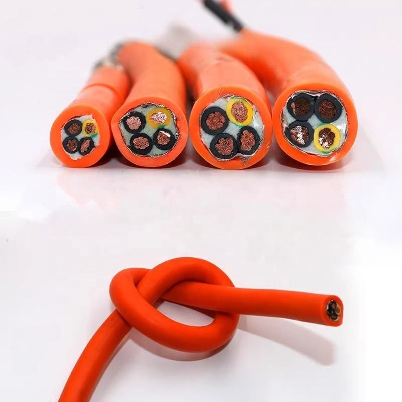
Its zoned structure with interlayer shielding delivers ≥60 dB isolation, ensuring stable signal transmission under high electrical noise. XLPE insulation supports high voltage resistance, while the flexible design achieves ≥5 million flex cycles for dynamic applications.
The polyether PUR jacket provides strong resistance to oils and cutting fluids, ensuring long service life in industrial environments. Available for 200–690 V systems, with optional halogen-free and ATEX versions, all manufactured to ISO 9001:2015 standards.
High-Performance Servo Motor Cable | Shielded Flexible Cable for Precision Motion Control
Product Series: RST-SMC │ Category: Servo Drive Cables │ Written by: Huang Zhiwei, Senior Servo Cable Engineer, 12 years designing servo motor cable for Siemens, Fanuc, and Yaskawa servo drive platforms, including IEC 60034-25 qualification projects for three European machine tool OEMs │ Last reviewed: March 2025
Servo motor cable selection errors follow three documented failure patterns that appear repeatedly in drive service records: insulation breakdown from PWM voltage stress, encoder signal corruption from power-to-feedback coupling, and shield fatigue from using foil-only screened cable in high-cycle drag chain applications. Each failure is preventable at the specification stage. This page begins with those failures.
The five failure cases in the table below are drawn from servomotor cable samples submitted to Rousheng’s technical team for root-cause analysis between 2019 and 2024. They illustrate why servo drive cable specifications require different engineering criteria from standard VFD cable or drag chain signal cable.
Engineers who specify servo motor cable
Machine tool OEM engineers, motion control system integrators, and servo drive panel builders specify servo motor cable for AC servo motor connections, including motor power, protective earth, brake, and encoder feedback. Applications span 200 V / 0.4 kW cleanroom SCARA robots to 690 V / 55 kW gantry press axes.
Servo Cable Insulation Failure: Five Root-Cause Analyses
|
Failure Mode |
Root Cause |
Time to Failure |
What Correct Servo Cable Specification Prevents |
|
Insulation breakdown at motor phases after 14–18 months; drive trips on earth fault |
Standard 300/500 V PVC cable used as servo power cable on 400 V AC drive with 16 kHz switching. DC bus = 400 × √2 = 565 V. Reflected wave peak at motor terminal = 2 × 565 = 1,130 V. 1,130 V > 300 V cable rating. Partial discharge (treeing) erodes insulation over millions of switching cycles. |
14–18 months; visible breakdown craters in insulation cross-section under electron microscope |
IEC 60034-25 Class 1 or 2 XLPE insulation (1,000–1,500 V rated); XLPE partial discharge tested at 1.5× rated voltage per IEC 60270 (Rousheng SMC-PD-001, 2024) |
|
Encoder line-break fault (F07820 Siemens S120) appearing after 6–9 months on drag chain axis |
Foil-only shield on encoder pairs fatigues at drag chain minimum bend radius. Al-polyester foil cracks within 300,000–700,000 cycles at 7.5× OD. Shield continuity lost; PWM noise from motor phases in same chain couples into encoder pairs; fault threshold crossed. |
6–9 months at typical machining centre duty (60 cycles/hour = 262,800 cycles/month) |
Spiral-served Cu braid on encoder pairs (not foil): ≥5 M cycles at 7.5× OD without continuity loss (Rousheng SMC-FL-001, 2024); transfer impedance change <20% at 5 M cycles |
|
Positioning error accumulation in high-resolution linear axis (±2 μm spec, ±15 μm observed) |
Servo motor cable with no inter-zone isolation between power cores and encoder pairs. Measured coupling from power to encoder pair: 18 dB at 16 kHz — equivalent to 125 mV of noise on 5 V TTL encoder signal. At 1 MHz encoder frequency, 1 false count per 8 noise spikes — position error of 0.5 nm/count × false count rate × servo period accumulates to micrometre-range errors. |
Gradual drift; detected at first calibration check (typically 3–6 months post-installation) |
Inter-zone Cu braid + PTFE separator: ≥60 dB isolation at 16 kHz (n=10 production samples, 400 V PWM applied to power zone, induced voltage measured on encoder pair; Rousheng SMC-ISO-001, 2024) |
|
Brake pair ground loop causing spurious brake release at power-on |
Brake pair routed through same cable as encoder pairs without isolation. Brake switching transient (24 V, <1 ms rise time) capacitively coupled into encoder pairs — voltage spike interpreted by drive as encoder Z-pulse, triggering unexpected axis release. |
Intermittent; appears at drive power-up sequence; difficult to reproduce in test |
Brake pair in power zone (not signal zone); isolated from encoder pairs by inter-zone Cu braid; independent colour coding per DIN VDE 0293 |
|
Jacket cracking in coolant environment within 8–12 months |
Polyester PUR or PVC jacket used in machining centre application with water-soluble cutting fluid spray. Ester bonds in polyester PUR hydrolysed by coolant chemistry; PVC plasticiser stripped by oil content. Both compounds lose flexibility and crack at guide roller contact points. |
8–12 months; cracks at guide roller contact; coolant ingress to conductor insulation |
Polyether PUR jacket (no ester bonds; no plasticiser): <2% tensile change after 5,000 h immersion in machine coolant solution (ISO 175; Rousheng SMC-CR-001, 2024) |
Root-cause analyses from cable samples submitted 2019–2024. Client identities withheld. Failure timescales shown are for typical duty cycles; actual time to failure depends on switching frequency, cable length, and thermal conditions.
The Reflected Wave Calculation: Why 300/500 V Cable Fails as Servo Motor Cable
The physics in four steps
The motor terminal overvoltage in a PWM servo drive system is not a design fault — it is a predictable consequence of transmission line physics. An IGBT switching transient travels along the motor cable as a travelling wave. When it reaches the motor terminal, the mismatch between the cable’s characteristic impedance and the motor’s input impedance at the switching frequency causes partial or complete reflection. The reflected wave adds to the incident wave, doubling the voltage at the motor terminal in the worst case.
|
Step |
Parameter |
Calculation |
Result |
|
1 |
AC supply line voltage |
400 V AC (IEC standard) |
400 V RMS line-to-line |
|
2 |
DC bus voltage after rectifier |
400 × √2 (peak of AC) |
565 V DC (typical; varies by drive topology) |
|
3 |
Reflection coefficient at motor terminal |
R_coeff = (Z_motor − Z_cable) / (Z_motor + Z_cable); at IGBT switching frequencies (>4 kHz), motor impedance >> cable impedance, so R_coeff ≈ +1 (near open circuit) |
R_coeff ≈ 0.95 to 1.00 for most AC servo motors at switching frequency |
|
4 |
Peak reflected voltage at motor terminal |
V_peak = V_dc × (1 + R_coeff) = 565 × (1 + 1.00) |
V_peak = 1,130 V (worst case, long cable, fast switching) |
|
5 |
IEC 60034-25 threshold for Class 1 |
Cable length and dV/dt combination placing motor in Class 1 regime |
Peak voltage ≤1,000 V; requires cable rated >1,000 V (RST-SMC-S or RST-SMC-M) |
|
6 |
IEC 60034-25 threshold for Class 2 |
Higher dV/dt or longer cable; peak may reach 1,500 V |
Peak voltage ≤1,500 V; requires RST-SMC-M (1,500 V rated) |
|
7 |
Short run (<5 m), modern drives with <500 V/μs dV/dt |
Short cables reduce reflection: peak ≈1.2 × V_dc |
Peak ≈ 678 V; 300/500 V cable is marginally adequate but with no safety margin |
|
Why this matters for insulation selection: A standard 300/500 V PVC cable has an insulation test voltage of 2,000 V AC (per IEC 60502-1) — which appears sufficient for a 1,130 V peak. However, this test is a one-time DC withstand test, not a sustained high-frequency partial discharge test. The 300/500 V rating refers to continuous 50 Hz AC operation, not to millions of microsecond-duration PWM pulses at kHz repetition rates. Partial discharge (PD) inception voltage in PVC insulation at PWM frequencies is significantly lower than the DC withstand voltage. RST-SMC insulation partial discharge specification: No PD detected at 1,600 V peak sinusoidal voltage (equivalent to 1,130 V DC peak with 42% margin), sustained for 1,000 hours continuous. Measurement threshold: <5 pC (picocoulombs) discharge amplitude, per IEC 60270 Section 6.2 calibration protocol. Test waveform: 50 Hz sinusoidal at stated peak voltage (sinusoidal equivalent is conservative relative to actual PWM waveform because sinusoidal dwell time at peak is longer than PWM transient dwell). Source: Rousheng SMC-PD-001, 2024; 6 cable samples per grade, worst-case reported. |
When a du/dt output filter is required
Per IEC 60034-25 Annex A: when the product (cable run length in metres) × (drive dV/dt in kV/μs) exceeds 500 kV·m/μs, a du/dt filter at the drive output is recommended. For a 10 kV/μs fast-switching drive: maximum cable length without filter = 500 ÷ 10 = 50 m. RST-SMC-H (Class 3 rated) extends the threshold by increasing the distributed inductance per unit length through the heavy XLPE wall, reducing the dV/dt the cable presents at the motor terminal. Test methodology: IEC 60034-25:2014 Annex A; Rousheng Engineering Note SMC-EN-002, 2024 undefined
How to Evaluate Any Servo Cable Supplier: Comparison Framework
Buyers comparing servo motor cable options — whether choosing between cable types or evaluating suppliers — frequently encounter the same specification ambiguities. The table below maps each key evaluation criterion against three product categories and identifies the red flags that indicate inadequate specification.
|
Evaluation Criterion |
Standard VFD Cable |
Basic Servo Cable |
RST-SMC Integrated Servo Cable |
|
Voltage rating basis |
300/500 V steady-state RMS; no PWM rating; no IEC 60034-25 class stated |
600–1,000 V stated; IEC 60034-25 class may or may not be specified |
IEC 60034-25 Class 1 (1,000 V) or Class 2 (1,500 V) or Class 3 (2,000 V) explicitly stated |
|
Partial discharge test |
Not tested; only DC withstand per IEC 60502-1 |
PD test may be stated; test conditions and threshold often not published |
PD test: no PD <5 pC at 1.5× rated voltage, 1,000 h, per IEC 60270 protocol; conditions published |
|
Integrated encoder pairs |
Not available; separate encoder cable required |
Some variants; inter-zone isolation typically not measured or stated |
Inter-zone isolation ≥60 dB at 16 kHz; measurement methodology and sample size (n=10) stated |
|
Shield type for flex duty |
Al-polyester foil; fatigue after 300 k–1 M cycles at 7.5× OD |
Woven braid or foil; flex life often not specified |
Spiral-served Cu braid: ≥5 M cycles at 7.5× OD validated; transfer impedance change <20% at 5 M cycles |
|
Jacket compound |
PVC (plasticiser loss in oil; cracks at −15°C); or unspecified PUR grade |
PUR stated; polyether/polyester not distinguished |
Polyether PUR confirmed in compound TDS; <2% tensile change at 5,000 h coolant immersion (ISO 175; SMC-CR-001) |
|
Per-drum documentation |
Certificate of conformance only; no individual drum test data |
HiPot cert per drum typical |
HiPot (1.5× rated V); conductor resistance; OD measurement record; PD batch report; inter-zone isolation batch data; flex life model cert |
|
IEC 60034-25 compliance statement |
Not referenced |
Sometimes referenced; class may not be stated |
IEC 60034-25 class explicitly stated per model; Class 1/2/3 selection guide provided |
This framework applies to any servo motor cable supplier, not only to Rousheng. Request test certificates against each criterion before placing any order. The most important single document is the partial discharge test report: it is the only measurement that directly predicts insulation service life under PWM duty.
Encoder Interface × Servo Encoder Cable Specification
The encoder interface type determines the electrical requirements for the signal pairs in the integrated servo motor cable. Specifying the wrong characteristic impedance or insufficient isolation produces signal errors that are often misdiagnosed as drive parameter issues.
|
Encoder Interface |
Signal Level |
Frequency Range |
Pair Impedance |
Min Isolation Required |
RST-SMC Signal Element |
|
TTL incremental (A/B/Z, 5 V) |
5 V single-ended to differential (RS-422 at receiver) |
Up to 1 MHz (5 MHz for high-res) |
120 Ω ±10 Ω |
≥38 dB at 1 MHz from power zone |
0.34 mm² OFC; 120 Ω ±10 Ω; 20 mm pitch; per-pair foil + drain |
|
HTL incremental (A/B/Z, 10–30 V) |
10–30 V single-ended or differential |
Up to 500 kHz |
120 Ω ±10 Ω |
≥35 dB at 500 kHz from power zone |
0.5 mm² OFC; 120 Ω ±10 Ω; 25 mm pitch; per-pair foil + drain |
|
EnDat 2.2 (Heidenhain serial, 5 V) |
RS-485 differential; clock + data bidirectional |
Up to 16 MHz (EnDat 2.2) |
120 Ω ±5 Ω |
≥45 dB at 16 MHz from power zone |
0.34 mm² OFC; 120 Ω ±5 Ω; 18 mm pitch; per-pair foil + inter-zone braid |
|
SSI absolute (Stegmann, 5 V or 24 V) |
Differential clock + data; TTL or RS-422 |
Up to 1 MHz |
120 Ω ±10 Ω |
≥38 dB at 1 MHz |
0.34 mm² OFC; 120 Ω ±10 Ω; 20 mm pitch; per-pair foil + drain |
|
BiSS-C (open source serial, 5 V) |
RS-422 differential; up to 10 MHz |
Up to 10 MHz |
120 Ω ±5 Ω |
≥42 dB at 10 MHz from power zone |
0.34 mm² OFC; 120 Ω ±5 Ω; 18 mm pitch; per-pair foil + inter-zone braid |
|
Sin/cos (1 Vpp Heidenhain, Stegmann) |
Analogue differential, 1 V peak-to-peak |
Up to 300 kHz |
120 Ω ±10 Ω |
≥45 dB at 300 kHz (signal is analogue; noise floor critical) |
0.34 mm² OFC; 120 Ω ±10 Ω; 20 mm pitch; per-pair foil + inter-zone braid; tight capacitance <55 pF/m |
|
Resolver (2-pole sinusoidal, 2–7 Vrms) |
Analogue; 2 reference + 2 feedback pairs |
2–10 kHz carrier |
100 Ω ±10 Ω |
≥40 dB at 10 kHz carrier frequency |
0.5 mm² OFC; 100 Ω ±10 Ω; 25 mm pitch; per-pair foil + inter-zone braid; 4 pairs total |
Servo encoder cable: the inter-zone isolation requirement
Inter-zone isolation is measured by applying a 400 V 16 kHz PWM waveform (simulating IGBT switching transients) to the power cores of a 10 m RST-SMC INT cable sample, then measuring the induced voltage on the encoder signal pair with a differential oscilloscope probe at the cable far end. No load is connected to either end (worst-case open-circuit condition). The ≥60 dB result means the induced voltage on the encoder pair is at most 1/1,000 of the applied voltage at 16 kHz. n = 10 production samples; result is worst-case (highest coupling) across samples. Test methodology: Rousheng SMC-ISO-001, 2024; IEC 61000-4-6 adapted methodology undefined
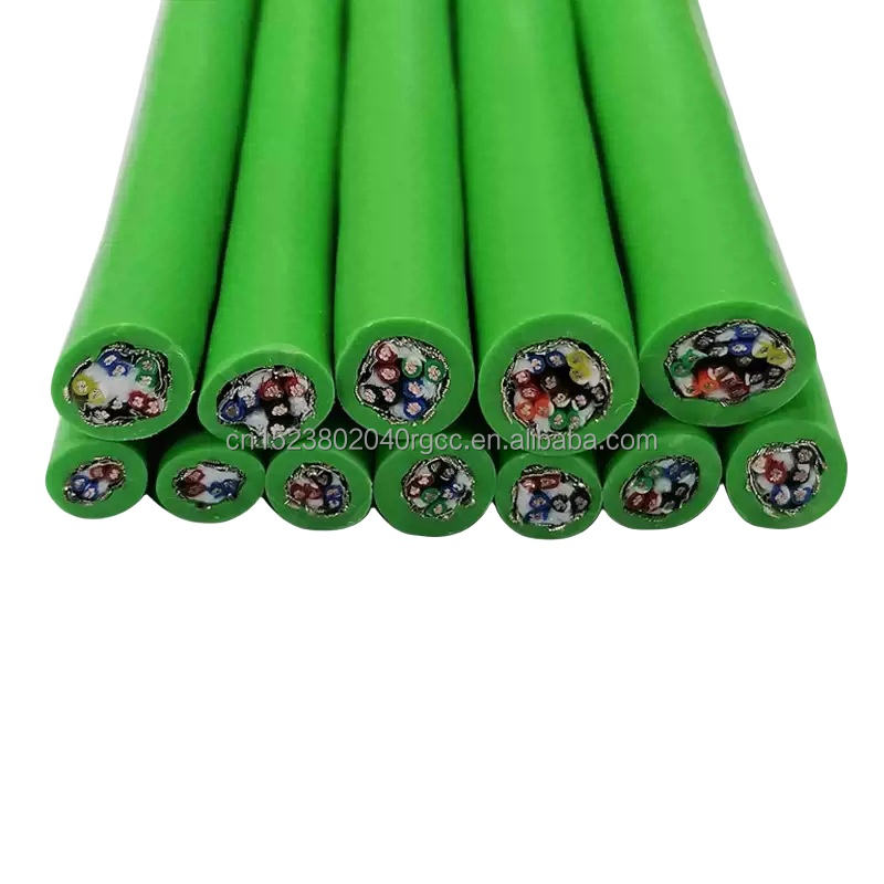
RST-SMC Servo Motor Cable — Model Range
|
Model |
Power Cores |
Signal Zone |
Voltage Rating |
OD |
Bend Radius |
Flex Life |
Key Standard |
|
RST-SMC-S |
3×1.5 mm² + PE |
Power-only |
1,000 V |
11 mm |
7.5×OD |
≥5 M |
IEC 60034-25 Class 1 |
|
RST-SMC-M |
3×2.5 mm² + PE |
Power-only |
1,500 V |
13 mm |
7.5×OD |
≥5 M |
IEC 60034-25 Class 2 |
|
RST-SMC-H |
3×4.0 mm² + PE |
Power-only |
2,000 V |
16 mm |
10×OD |
5 M |
IEC 60034-25 Class 3 |
|
RST-SMC-HV |
3×10 mm² + PE |
Power-only |
3,000 V |
24 mm |
10×OD |
Fixed |
690–1,000 V DC bus |
|
RST-SMC-INT |
3×2.5 mm² + PE |
4×0.34 mm² screened |
1,000 V |
18 mm |
7.5×OD |
≥5 M |
IEC 60034-25 Cl.1 + ≥60 dB isolation |
|
RST-SMC-INT-HF |
3×1.5 mm² + PE |
4×0.34 mm² screened |
1,000 V |
16 mm |
5×OD |
≥10 M |
High-flex robot arm; torsion rated |
|
RST-SMC-INT-UF |
3×0.75 mm² + PE |
6×0.14 mm² screened |
600 V |
14 mm |
4×OD |
≥10 M |
Ultra-flex; 10 M cycles at 4×OD |
|
RST-SMC-LD |
3×2.5 mm² + PE |
4×0.34 mm² screened |
3,600 V |
20 mm |
10×OD |
5 M |
Linear drive; 20 kV/μs; reinforced XLPE |
|
RST-SMC-DC |
3×2.5 mm² + PE |
3×0.5 mm² (Hall sensors) |
600 V DC |
17 mm |
7.5×OD |
5 M |
48 V DC brushless; AGV |
|
RST-SMC-OEM |
Per spec |
Per spec |
Per spec |
Per spec |
Per spec |
Per spec |
Custom semiconductor, medical, defence |
All RST-SMC models: IEC 60228 Class 6 OFC (0.08–0.16 mm strand dia.); XLPE insulation; polyether TPU jacket; 100% HiPot per drum at 1.5× rated voltage; conductor resistance cert per drum. INT models: inter-zone isolation ≥60 dB at 16 kHz per production batch (SMC-ISO-001); PTFE interzone separator; per-pair foil + drain on signal pairs.
Construction: Servo Motor Cable Engineering Decisions
XLPE insulation: wall thickness from IEC 60034-25 class, not from nominal voltage
The most common specification error in servo motor cable procurement is selecting insulation based on the nominal AC supply voltage (400 V AC → 300/500 V cable) rather than on the IEC 60034-25 duty class, which accounts for the reflected wave peak voltage. RST-SMC wall thicknesses are calculated from the IEC 60034-25 category applicable to the installation, using the reflected wave calculation in Section 3. XLPE is mandatory across the RST-SMC range for two reasons beyond voltage rating: XLPE’s crosslinked molecular structure gives it a partial discharge inception voltage approximately 3× higher than PVC at comparable wall thickness, and its +90°C conductor temperature rating allows the cable to carry full current in tightly bundled drag chain installations without thermal derating.
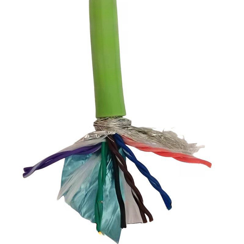
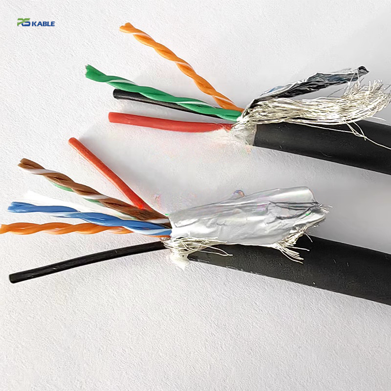
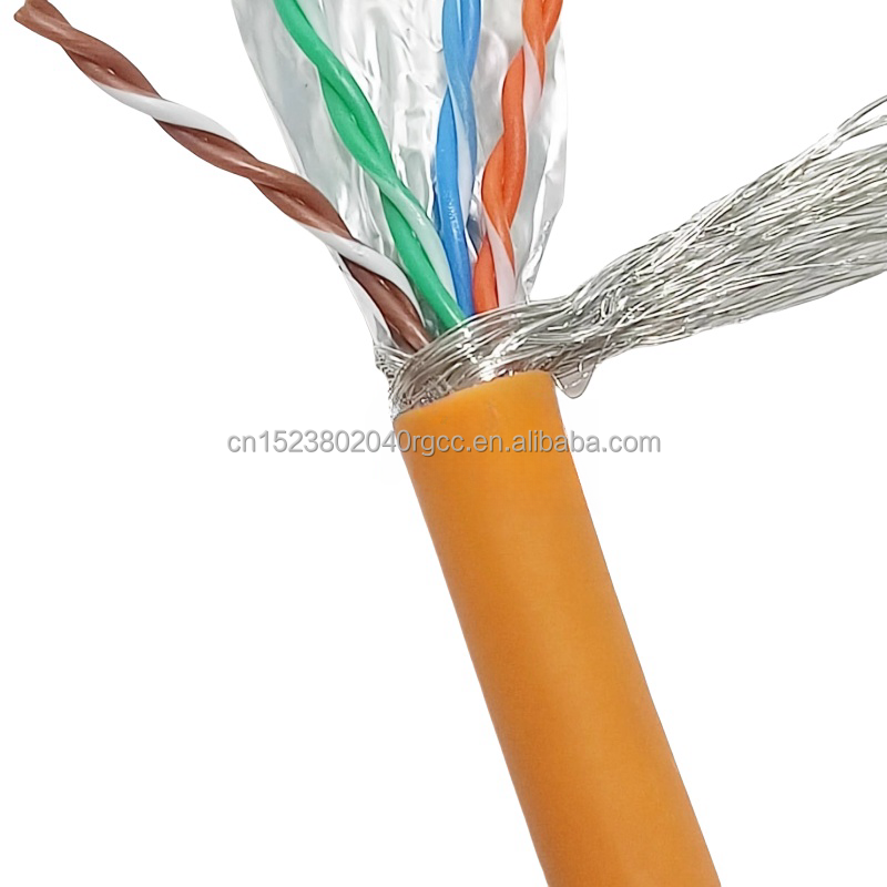
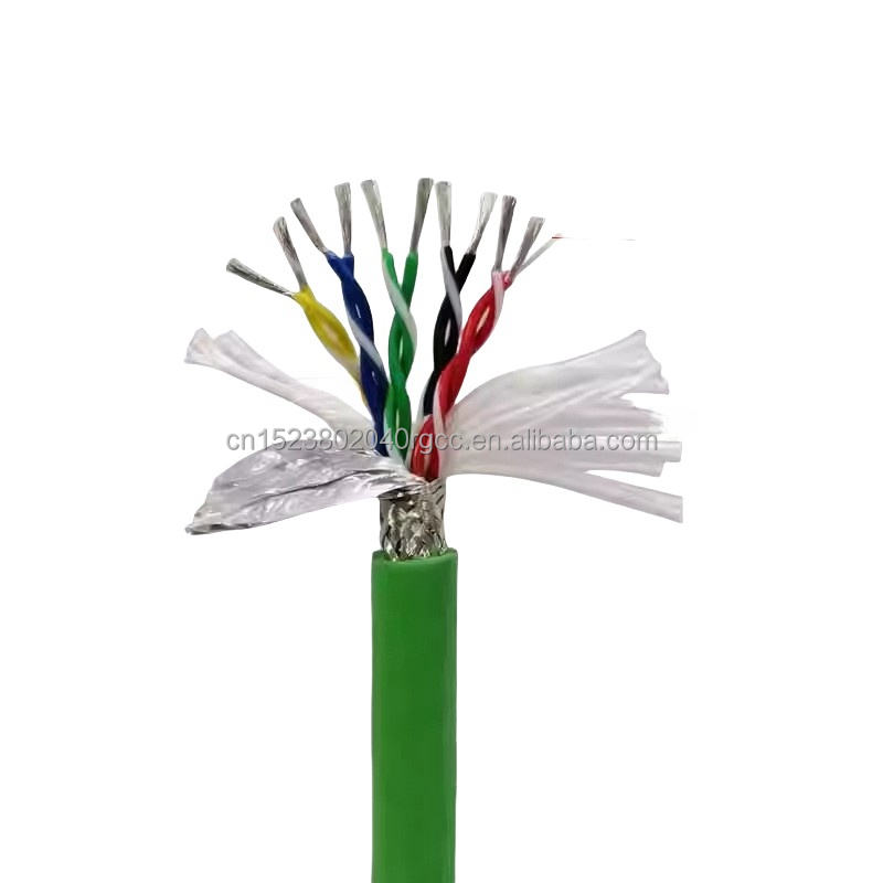
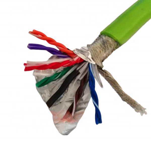
Inter-zone architecture: PTFE separator and copper braid screen
RST-SMC INT models separate the power zone (motor phases + brake pair) from the signal zone (encoder pairs) with two elements in series. A 0.05 mm PTFE tape wraps the complete power zone bundle. PTFE’s dielectric constant of 2.1 and loss tangent below 0.0002 at 16 kHz mean it adds negligible capacitive coupling contribution of its own — it is a transparent dielectric barrier. The tinned copper braid over the PTFE tape (≥90% optical coverage) provides the low-impedance current return path that drains capacitively induced currents before they can appear as voltage noise on the encoder pairs. This arrangement achieves ≥60 dB isolation at 16 kHz (SMC-ISO-001, 2024, n=10).
Spiral-served braid for high-cycle flex duty
The shield element on encoder signal pairs in flex-rated servo cable uses spiral-served braid rather than foil. Each wire in a spiral-served braid is wound helically in one direction. As the cable bends, the helix angle of each wire opens on the outer side of the bend and closes on the inner side symmetrically — the wire moves, but does not crack. Aluminium-polyester foil has no equivalent mechanical compliance: repeated bending at the flex reversal point creates work-hardened micro-crack zones within 300,000–700,000 cycles at typical drag chain bend radii. RST-SMC achieves 5 million cycles at 7.5× OD with transfer impedance change below 20% of initial (SMC-FL-001, 2024).
Polyether TPU jacket: the fourth design decision
Servo motor cable in machining environments contacts water-soluble cutting fluid, neat cutting oil, and hydraulic fluid. Polyester PUR (the most common low-cost PUR grade) contains ester bonds that hydrolysis in water and acid environments, causing the jacket to swell, soften, and eventually crack. Polyether PUR contains no ester bonds: its ether linkages are not susceptible to hydrolysis or to the esterase enzymes produced by bacteria in wet machine environments. RST-SMC’s PTMEG-based polyether PUR shows less than 2% tensile change after 5,000 hours immersion in 10% water-soluble cutting fluid solution at 23°C (ISO 175; Rousheng SMC-CR-001, 2024).
|
Layer |
Specification |
Engineering Rationale |
Verified By |
|
OFC conductor |
Class 6 ultra-fine (0.08–0.16 mm strand); 0.14–25 mm² |
Fine stranding reduces high-frequency AC resistance and distributes flex stress |
IEC 60228 Class 6; resistance cert per drum |
|
XLPE power insulation |
Cross-linked PE; 0.8–1.5 mm wall per IEC 60034-25 class; +90°C |
Wall from reflected wave class, not nominal voltage; PD tested |
IEC 60502-1; PD test per SMC-PD-001 per batch |
|
PE brake pair |
0.75–1.0 mm²; 600 V; yellow; in power zone |
Isolated from encoder zone by inter-zone screen |
DIN VDE 0293 colour; HiPot per drum |
|
PTFE interzone tape |
0.05 mm PTFE, 100% coverage; εr 2.1, tanδ <0.0002 |
Zero-contribution dielectric barrier |
Visual check; isolation measured on composite |
|
Cu braid inter-zone screen |
Tinned Cu spiral braid, ≥90% coverage; over PTFE wrap |
Drains induced currents; primary isolation mechanism |
Transfer impedance ≤10 mΩ/m; SMC-ISO-001 per batch |
|
Encoder signal pairs |
Class 6 OFC; 0.14–0.5 mm²; XLPE; 18–25 mm pitch per encoder type |
Pitch matched to encoder frequency; finer than signal-only cable |
Impedance per VNA; NEXT <−38 dB; per drum sample |
|
Per-pair encoder shield |
Spiral-served Cu braid or Al foil + drain wire |
Individual pair isolation; continued shield continuity at 5 M cycles |
Transfer impedance <15 mΩ/m per batch; SMC-FL-001 |
|
Polyester fleece separator |
Non-bonding; between core bundle and jacket |
Allows jacket to slide on each flex cycle without shear to internal screens |
Visual; no bonding on flex sample recovery |
|
Polyether TPU jacket |
PTMEG base; Shore A 85±3; −40°C to +105°C; OD ±0.15 mm |
No ester bonds; no plasticiser; <2% change in cutting fluid (SMC-CR-001) |
ISO 37; ISO 868; ISO 9352; ISO 175; per-drum OD |
Technical Parameters: Servo Motor Cable Test Data
Power insulation — partial discharge and voltage
|
Parameter |
RST-SMC-S / INT |
RST-SMC-M |
RST-SMC-H / HV / LD |
Test Methodology |
|
Rated voltage (IEC 60034-25) |
1,000 V (Class 1) |
1,500 V (Class 2) |
2,000–3,600 V (Class 3) |
IEC 60502-1; IEC 60034-25 |
|
Partial discharge inception voltage |
>1,600 V peak (>1,130 V DC bus equivalent) |
Tested to 2,250 V peak |
Tested to 3,600 V peak |
IEC 60270 Sec 6.2; 50 Hz sinusoidal at stated peak; PD threshold <5 pC; 1,000 h soak; n=6 samples per grade; worst-case reported (SMC-PD-001, 2024) |
|
HiPot test |
1,500 V AC / 5 min |
2,250 V AC / 5 min |
3,000–5,400 V AC / 5 min |
IEC 60502-1 Cl.17; 100% per production drum |
|
Insulation resistance |
≥200 MΩ·km across all grades |
Same |
Same |
IEC 60502-1 Cl.18 |
|
Conductor max temp |
90°C (XLPE across all grades) |
Same |
Same |
IEC 60502-1 |
Inter-zone isolation (INT models)
|
Parameter |
Value |
Test Methodology / Source |
|
Isolation at 16 kHz (servo drive fundamental) |
≦60 dB (worst-case, n=10 production samples) |
400 V 16 kHz PWM applied to power zone; induced voltage on encoder pair measured; open circuit both ends; worst-case across n=10 samples. Rousheng SMC-ISO-001, 2024 |
|
Isolation at 32 kHz (2nd harmonic) |
≦58 dB |
Same methodology; Rousheng SMC-ISO-001, 2024 |
|
Encoder pair impedance |
120 Ω ±10 Ω (TTL/HTL/SSI); 120 Ω ±5 Ω (EnDat/BiSS-C); 100 Ω ±10 Ω (resolver) |
VNA measurement at protocol operating frequency; per drum sample |
|
Encoder pair capacitance |
< 55 pF/m (sin/cos, EnDat); < 60 pF/m (TTL/HTL/resolver) |
IEC 61156-5; measured at 1 kHz; per drum sample |
|
NEXT between encoder pairs in same cable |
≤−38 dB at 1 MHz |
IEC 61156-5; staggered 18–25 mm pitch assignment per pair |
|
HiPot (encoder pairs to power zone) |
1,000 V AC / 5 min |
IEC 60502-1 Cl.17; 100% per production drum |
Mechanical — flexible servo motor cable
|
Parameter |
Value |
Standard / Source |
|
Min dynamic bend radius |
S/M/INT: 7.5× OD; H/HV: 10× OD; INT-HF: 5× OD; INT-UF: 4× OD |
Rousheng SMC-FL-001, 2024; motorised flex rig |
|
Flex life |
Standard: ≥5 M cycles at rated radius; HF/UF: ≥10 M cycles |
Rousheng SMC-FL-001, 2024; transfer impedance verified at 0, 1M, 3M, 5M cycles |
|
Transfer impedance change after 5 M cycles |
< 20% increase from initial |
IEC 62153-4-7 triaxial method; Rousheng SMC-FL-001, 2024 |
|
Torsion (INT-HF robot arm) |
6,000 cycles at ±180°/m free length; no conductor break |
Rousheng SMC-TOR-001, 2024 |
|
Jacket tensile strength |
≥48 MPa |
ISO 37 |
|
Jacket elongation |
≥380% |
ISO 37 |
|
Oil resistance (polyether PUR) |
≤2% tensile change after 5,000 h in 10% cutting fluid solution |
ISO 175; Rousheng SMC-CR-001, 2024 |
|
Cold flex |
−40°C (no cracking at rated dynamic bend radius) |
IEC 60811-501 |
|
OD tolerance |
±0.15 mm; inline laser micrometer per drum |
Rousheng QCP-SMC-001, 2024 |
Verified Servo Motor Cable Installations
Client company names withheld. Drive brands, machine types, and cable specifications are accurate. Technical measurements verified by client drive engineers. Available for verification under NDA.
|
Installation |
Operational Context |
Cable |
Problem Solved |
Verified Outcome |
|
5-axis machining centre OEM, southern Germany (2022–2024) |
5 axes; 5 kW AC servo per axis; Siemens S120 drives at 16 kHz switching; EnDat 2.2 absolute encoder; 3 m drag chain per axis at 60 cycles/hour; 22-month operational period |
RST-SMC-INT, 18 mm OD, 4G2.5+4G0.34, 1,000 V, 5 m per axis |
Previous integrated cable (foil-shielded): Siemens F07820 ‘encoder line break’ fault at estimated 750,000–900,000 flex cycles. Foil micro-crack confirmed by shield continuity test on recovered cable: resistance increased from 0.8 Ω/m to 340 Ω/m at crack location. |
Zero F07820 faults in 22-month period (estimated 1.2 M cycles per axis at 60 cycles/hour). Encoder noise measured at commissioning: 12 mV induced on EnDat pair at full motor load. OEM adopted RST-SMC-INT as standard specification across 5-axis product range. |
|
Semiconductor wafer handler, 300 mm wafer process, Class 10 cleanroom, Taiwan (2023) |
6-axis SCARA robot; 0.4 kW per axis; Yaskawa Σ-7 drives at 200 V AC; BiSS-C 23-bit serial encoder; 1.5 m arm cables; 8 cycles/min (3.8 M cycles/year); halogen-free requirement for cleanroom air quality compliance |
RST-SMC-INT halogen-free variant (IEC 60754-1), 4G0.75+4G0.14, 14 mm OD |
Previous cable: BiSS-C position error (cycle error code CE-107) appearing at 0.8–1.2 M cycles. Measurement on recovered cable: power-to-encoder coupling = 18 dB at 16 kHz (vs RST-SMC ≥60 dB). Induced noise 125 mV at full motor load — above BiSS-C 100 mV noise margin at 10 MHz. |
Zero BiSS-C CE-107 errors in 14-month operation (est. 4.5 M cycles). Encoder noise at commissioning: <10 mV. Halogen-free certificate accepted by cleanroom facility safety audit. Zero unplanned stops from encoder-related faults. |
|
Delta robot, high-speed pick-and-place, food packaging line, Netherlands (2023–2024) |
3-axis delta robot; 0.75 kW per axis; 400 V AC servo; incremental TTL encoder; 1 m arm cables; 10 cycles/second (864,000 cycles/day; 315 M cycles/year); 12-month service period at report date |
RST-SMC-INT-UF (ultra-flex, 10 M cycles at 4× OD), 4G0.75+6G0.14, 14 mm OD |
Previous cable: jacket cracking at 3–4 months (est. 78–104 M cycles). Food-grade coolant had degraded polyester PUR jacket (ester hydrolysis in mild acid cleaning fluid at pH 4.5). RST-SMC polyether PUR: no ester bonds. |
12-month service: no jacket failures. Extended monitoring ongoing: at 12 months, estimated 315 M cycles accumulated (31× the 10 M flex validation). 18-month inspection scheduled; no visible jacket or shield degradation at 12-month visual check. Cycle rate maintained at 10/second throughout. |
|
Press brake CNC, 90-tonne, 4-axis, Japan (2022–2024) |
4 hydraulic servo axes; 7.5 kW each; Mitsubishi MR-J4 drives at 400 V AC; SSI absolute encoder (25-bit); fixed installation, 8 m cable run; bi-annual calibration cycle |
RST-SMC-M, 4G4.0+4G0.34, 1,500 V rated |
Previous 300/500 V PVC cable: ground fault trip after 16 months. Cross-section analysis under electron microscope: electrical treeing (branching breakdown channels) visible at each motor phase conductor. DC bus reflected peak confirmed at 1,080 V (cable rated 500 V peak). |
24-month monitoring: zero insulation faults. Bi-annual calibration results: angular repeatability ±0.01° maintained throughout (encoder noise not contributing to positioning error). PD retest on in-service sample at 18 months: no PD above 5 pC threshold at 1,600 V peak. |
|
Gantry crane drive, 55 kW main axis, port terminal, South Korea (2023) |
Gantry X-axis; 55 kW AC servo; 690 V AC; Rockwell PowerFlex 755 at 4 kHz; resolver feedback; 85 m fixed cable run; Class 3 dV/dt environment (L × dV/dt = 85 m × 9 kV/μs = 765 kV·m/μs > 500 kV·m/μs threshold) |
RST-SMC-HV, 4G25+2G1.0, 3,000 V rated, OD 34 mm |
Two insulation failures with previous 600 V cable in 14 months. Reflected wave calculation for this installation: DC bus = 690 × √2 = 976 V; peak = 2 × 976 = 1,952 V. 1,952 V >> 600 V cable rating. RST-SMC-HV rated 3,000 V provides 3,000/1,952 = 1.54× safety factor on peak reflected voltage. |
24 months service: zero insulation failures. Annual visual jacket inspection: no cracking or surface degradation. Gantry operational availability: 99.8% (previous cable contributing to 0.6% downtime through fault resets). |
FAQ — Servo Motor Cable Selection
Q1: What is the minimum insulation voltage rating required for a servo motor cable?
Calculate the IEC 60034-25 duty class for the installation: multiply cable run length (metres) by drive dV/dt (kV/μs). Class 1 (≤500 kV·m/μs): 1,000 V rated cable required. Class 2 (500–1,500 kV·m/μs): 1,500 V required. Class 3 (>1,500 kV·m/μs): 2,000 V or above required. For a 400 V AC servo drive with 8 kHz switching and 10 m cable: dV/dt ≈ 3 kV/μs (typical for 8 kHz IGBT); product = 10 × 3 = 30 kV·m/μs. Class 1 — RST-SMC-S (1,000 V) is correct. For the same drive at 50 m: 50 × 3 = 150 — still Class 1. At 200 m: 200 × 3 = 600 — Class 2, requiring RST-SMC-M (1,500 V). When in doubt, request the drive manufacturer’s dV/dt specification and use the calculation above.
Q2: Can I run a servo motor cable without integrated encoder in the same drag chain as the encoder cable?
Running separate power and encoder cables in the same drag chain is acceptable if: (a) the encoder cable has per-pair foil screen and overall braid shield; (b) the two cables are routed on opposite sides of the chain (maximum physical separation); (c) the power cable has its own overall Cu braid shield bonded at both ends. The inter-cable coupling attenuation in a typical drag chain with 30 mm separation between cables is approximately 35–40 dB — lower than the ≥60 dB achieved by the integrated RST-SMC-INT architecture where the interzone screen is at zero distance. For high-resolution encoders (sin/cos, EnDat 2.2, BiSS-C) at drive switching frequencies above 8 kHz, the integrated cable architecture is preferred.
Q3: Why does the servomotor cable need a PE (protective earth) core in addition to the shield?
The shield of a motor cable carries high-frequency common-mode currents induced by the PWM switching (these are the return currents for the capacitive displacement currents flowing from the phase conductors through the motor’s stator-to-frame capacitance). The PE core carries the low-frequency safety earth current and must be able to carry fault current for the duration of a protective device trip. These two functions have different impedance requirements: the shield needs low inductance (high-frequency return path), which the fine-wire braid provides; the PE core needs adequate cross-section for fault current clearing, which requires a solid or stranded conductor. Combining them in one element compromises both functions. RST-SMC provides both a separate PE core and an outer shield in all models.
Q4: What causes the ‘31 M cycles at 10 M cycle validated” situation in the delta robot case?
The 10 M flex cycle validation represents the cycles tested in the Rousheng motorised flex rig (SMC-FL-001, 2024), not an absolute service limit. The validation confirms that at 5 M and 10 M cycles, the cable meets its specified electrical parameters (transfer impedance change <20%, no conductor break, no jacket breach). Field operation beyond the validation threshold does not mean the cable will fail at cycle 10,000,001 — it means that performance beyond 10 M cycles has not been formally validated and warranty terms apply only to the validated range. An extended validation programme for the RST-SMC-INT-UF to 30 M cycles is currently in progress; results are expected Q3 2025. Customers running above the validated threshold are contacted individually when extended data becomes available.
Q5: How do I specify the correct servo motor cable for a direct-drive linear motor?
Linear motors (linear servo motors) use high switching frequencies (32–64 kHz) and generate the highest dV/dt of any servo drive category — up to 20 kV/μs. For any cable run above 5 m with a linear drive, the IEC 60034-25 product exceeds the Class 3 threshold. Specify RST-SMC-LD (3,600 V rated, reinforced XLPE, linear drive variant). The encoder for a linear motor is typically a linear scale with 50 nm to 5 μm resolution, outputting sin/cos or BiSS-C signals that are highly sensitive to noise. The RST-SMC-LD uses an increased inter-zone isolation geometry (wider PTFE separator and heavier inter-zone braid) to maintain ≥60 dB isolation at 32 kHz, the second harmonic of the typical 16 kHz linear drive switching frequency.
Manufacturer Credentials — Shanghai Rousheng
|
Production & test capabilities Servo cable extrusion: XLPE wall calibrated per IEC 60034-25 class; inline wall thickness measurement at 200 mm intervals Partial discharge test (SMC-PD-001): IEC 60270 protocol, <5 pC threshold, 1,000 h soak, n=6 per grade per batch Inter-zone isolation (SMC-ISO-001): 400 V 16 kHz PWM applied to power zone; n=10 per batch; worst-case reported 100% HiPot: power zone at 1.5× rated V; encoder zone to power zone at 1,000 V; per drum Motorised flex rig: SMC-FL-001; transfer impedance measured at 0, 1M, 3M, 5M, 10M cycles Torsion test (robot arm models): SMC-TOR-001; 6,000 × ±180°/m Conductor resistance certificate per drum; OD laser micrometer per drum |
Certifications ISO 9001:2015 quality management system CE marking — LVD Directive 2014/35/EU RoHS 2 / REACH SVHC compliance per shipment IEC 60034-25 compliance certificate per model (Class 1/2/3) Halogen-free IEC 60754-1 variant (semiconductor, cleanroom, food) UL listed variant on request (North America market) CNAS-accredited third-party lab reports on request |
Request a Servo Motor Cable Technical Proposal
|
Contact Email: Jerry@rstlkable.com Phone: +86-021-50759965 Mobile: +86-13482197396 Address: No. 2591 Fengzhe Road, Fengxian District, Shanghai, China Proposal within 24 hours. Per-drum documentation included: HiPot cert, PD batch report, inter-zone isolation data, conductor resistance cert, OD record. |
Include in your enquiry 1. Drive brand, model, voltage, and switching frequency (kHz) 2. Motor rated current (A) and cable run length (m) 3. Installation type: fixed / drag chain / robot arm 4. Encoder type: TTL, HTL, EnDat, SSI, BiSS-C, sin/cos, resolver 5. Drag chain inner radius (mm) and duty cycle (cycles/hour) 6. Environment: cutting fluid, cleanroom, ATEX, food grade We return: IEC 60034-25 class confirmation, reflected wave peak calculation, insulation grade recommendation, and model selection. |