Floating Fiber Optic Cable | Lightweight Buoyant Fiber Cable for Marine Communication Systems
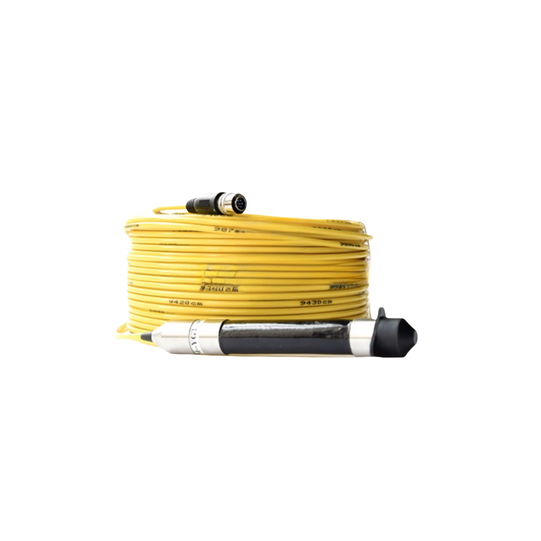
The RST-FFC Series Floating Fiber Optic Cable is a buoyant fibre cable designed for marine surface communication, buoy systems, USV/UAV tethers, and emergency deployments.
With a density of 0.85–0.92 g/cm³, it delivers stable positive buoyancy, keeping the cable afloat without ROV or diver support. A near-neutral buoyancy option (1.00±0.01 g/cm³) is available for freshwater applications.
Built with Kevlar tensile members (0.8–2.5 kN) and G.657.A1 fibre, it ensures flexibility, durability, and low attenuation during dynamic movement. The UV-resistant polyether TPU jacket supports long-term surface exposure with high-visibility color options.
Certified to ISO 9001:2015, compliant with CE, RoHS, REACH, with optional DNV/BV approval. Supplied with buoyancy test reports, OTDR data, and tensile certificates.
Floating Fiber Optic Cable | Lightweight Buoyant Fiber Cable for Marine Communication Systems
Product Series: RST-FFC │ Category: Surface & Near-Surface Marine Fiber Cables │ Reviewed by: Rousheng Marine Cable Engineering Team
The engineering question that defines this product category: why does a marine fiber optic cable need to float?
The answer is not obvious until you consider what happens to a negatively buoyant cable deployed between two surface platforms — a ship and a buoy, two vessels in formation, or a vessel and a shore station. A negative-buoyancy cable sinks. It hangs in a catenary below the water surface, where it is susceptible to propeller strike, anchor fouling, net entanglement, and tidal current drag that loads the termination points asymmetrically. Recovering a fouled negatively buoyant cable in open water requires a diver or ROV and takes hours. In a naval exercise or emergency communications scenario, that is operationally unacceptable.
A floating fiber optic cable eliminates these failure modes by remaining at or just below the water surface. It is visible to vessels, recoverable by hand from a RIB or patrol craft, and imposes near-zero catenary load on its termination points. The trade-off is a more complex cable construction: achieving positive or near-neutral buoyancy in a cable that must also protect glass optical fibers from mechanical damage requires precise density engineering of every material in the cross-section.
The Engineering of Buoyancy — How a Fiber Cable Floats
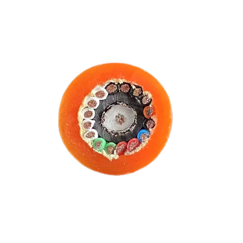
Achieving positive buoyancy in a fiber optic cable requires the average cable density to be less than the water it displaces (1.025 g/cm³ for seawater, 1.000 g/cm³ for fresh water). Every element in the cable cross-section contributes to this density calculation. The table below shows how RST-FFC achieves its target density of 0.85–0.92 g/cm³ — ensuring positive buoyancy in both fresh water and seawater with a reserve margin.
|
Material / Element |
Density (g/cm³) |
Role in Buoyancy Design |
Contribution |
|
Optical fibre (silica glass) |
2.20 |
Weight penalty — cannot be eliminated; minimised by reducing fibre count and using smallest viable tube ID. |
Negatively buoyant; minimised by selecting only required fibre count. |
|
PBT loose tube |
1.31 |
Slightly negative; necessary for fibre protection. Minimised by using thin-wall tubes (0.4 mm wall). |
Minor weight penalty; essential for fibre protection. |
|
Petroleum gel fill |
0.85 |
Slightly positive in fresh water, near-neutral in seawater. Provides water-blocking without significant weight. |
Minor buoyancy contribution; primarily functional. |
|
Closed-cell foam core |
0.05–0.12 |
Primary buoyancy element. Extruded closed-cell polyethylene or polypropylene foam occupies the cable centre and interstitial spaces. Foam density calibrated to achieve target cable density. |
Major positive contribution; critical buoyancy component. |
|
Kevlar tensile member (parallel lay) |
1.44 |
Slightly negative; necessary for tensile load bearing. Minimised by using only the required load rating. |
Minor weight penalty; necessary for mechanical integrity. |
|
Polyurethane outer jacket (polyether grade) |
1.20 |
Slightly negative; necessary for protection. Wall thickness minimised consistent with abrasion and UV requirements. |
Minor weight penalty; minimised by using thin-wall extrusion. |
|
Target cable assembly density |
0.85–0.92 |
Positive buoyancy in both fresh water (1.00) and seawater (1.025) with margin of 0.08–0.18 g/cm³. |
Cable floats at surface with freeboard of approximately 15–30% of OD above waterline. |
Foam density is adjusted during extrusion to hit the target cable assembly density within ±0.02 g/cm³. Each RST-FFC drum is tested for buoyancy by immersing a 1 m sample in fresh water and seawater — buoyancy test certificate included with every order.
Where Floating Fiber Optic Cable Is Specified
Floating fiber optic cable is specified when the operational environment makes a negatively buoyant cable impractical, hazardous, or unrecoverable. The nine scenarios below represent the primary deployment contexts for the RST-FFC series.
|
⚓ Ship-to-Ship Communications Open ocean, vessels in formation Cable must float to avoid propeller strike from either vessel. Recovery between ships requires surface visibility. |
⛵ Vessel-to-Shore Fiber Link Harbour, anchorage, coastal Floating cable avoids fouling on seabed anchors and mooring chains in busy anchorages. Recoverable by harbour launch. |
⛴ Naval Tactical Communications Fleet exercises, mine countermeasures Rapid deployment and recovery from patrol craft. Zero catenary load prevents termination stress during high-speed transit. |
|
⚡ Temporary Offshore Power & Data Installation vessel, offshore platform approach Short-duration high-bandwidth link during platform commissioning. Floating cable avoids entanglement with supply vessel anchors. |
Ὧ6 Oceanographic Research Buoy Array Open ocean, extended mooring Surface sensor buoys connected by floating fiber avoid inter-buoy catenary drag that distorts array geometry. |
⛈ Disaster Response Communications Post-disaster coastal, harbour debris field Floating cable is deployable from a small boat without dive support. Visible from surface for route inspection and rapid recovery. |
|
✈ UAV & USV Data Relay Tether Surface, near-shore operations Lightweight floating tether for unmanned surface vessels (USV) and surface-launched UAV fiber tethers. Low drag, no sinking risk. |
⚓ Dive Support & Saturation Systems Offshore diving support vessels Floating surface cable between diving support vessel and decompression barge. Avoids entanglement with diver umbilicals below. |
⚽ Marine Scientific Survey Vessels Research vessel operations Temporary high-bandwidth link between survey vessel and instrument deployment ship during multi-vessel scientific operations. |
RST-FFC Series — Model Specifications
|
Model |
Fibre Type & Count |
Cable Density |
Tensile Rating |
OD |
Buoyancy in Seawater |
UV Rating |
Primary Use |
|
RST-FFC-2SM |
2× SM G.657.A1 |
0.88 g/cm³ |
Kevlar 0.8 kN |
14.0 mm |
+55 N/100 m |
1,000 h xenon |
Ship-to-ship comms, short tactical link |
|
RST-FFC-4SM |
4× SM G.657.A1 |
0.90 g/cm³ |
Kevlar 1.2 kN |
16.5 mm |
+60 N/100 m |
1,000 h xenon |
Vessel-to-shore, research buoy array |
|
RST-FFC-8SM |
8× SM G.657.A1 |
0.91 g/cm³ |
Kevlar 2.0 kN |
20.2 mm |
+58 N/100 m |
2,000 h xenon |
Naval tactical link, multi-channel comms |
|
RST-FFC-4SM+P |
4× SM G.657.A1 + 2× power pair 1.5 mm² |
0.92 g/cm³ |
Kevlar 1.5 kN |
19.8 mm |
+52 N/100 m |
1,000 h xenon |
Powered buoy, remote instrument with data + power |
|
RST-FFC-12SM |
12× SM G.657.A1 |
0.91 g/cm³ |
Kevlar 2.5 kN |
23.6 mm |
+50 N/100 m |
2,000 h xenon |
Dense comms array, multi-vessel scientific ops |
|
RST-FFC-4MM |
4× MM OM4 50/125μm |
0.87 g/cm³ |
Kevlar 1.0 kN |
15.8 mm |
+62 N/100 m |
1,000 h xenon |
Short-range (<550 m) high-BW video, dive support |
|
RST-FFC-NB |
4× SM G.657.A1 |
1.00±0.01 g/cm³ |
Kevlar 1.2 kN |
17.0 mm |
Near-neutral (±10 N/100 m) |
1,000 h xenon |
USV tether, AUV surface recovery, UAV fiber tether |
|
RST-FFC-OEM |
1–48 fibres, SM/MM/custom |
0.80–1.02 g/cm³ target |
Per spec |
Per spec |
Per spec |
Per spec |
Naval, research, custom buoyancy profile |
Buoyancy force in seawater (1.025 g/cm³) shown as net upward force in Newtons per 100 m of cable. Positive values indicate floating cable. RST-FFC-NB (near-neutral) is tuned for 0±10 N/100 m: floats in fresh water, near-neutral in seawater. UV rating per IEC 60811-401 xenon arc test with ≤80% tensile retention.
Sea-State Performance — How RST-FFC Behaves in Real Conditions
A floating fiber cable’s performance is inseparable from the sea state it is deployed in. Wave action and surface currents create dynamic loading on the cable that affects its surface position, termination tension, and optical performance. The table below maps Beaufort sea states to RST-FFC cable behaviour — a level of operational detail absent from most floating cable data sheets.
|
Sea State (Beaufort) |
Wave Height |
Surface Current |
Cable Behavior |
RST-FFC Recommendation |
|
0–1 (Calm / Light air) |
<0.1 m |
<0.3 kts |
Cable lies flat at surface. Zero catenary load. Fully visible. Propeller-strike risk from slow-moving vessels. |
All models suitable. Mark cable ends with reflective buoys in commercial traffic areas. |
|
2–3 (Light / Gentle breeze) |
0.1–0.9 m |
0.3–1.5 kts |
Cable develops gentle surface wave following the swell. Termination load remains <5% of Kevlar rated capacity. Optical performance unaffected. |
All models suitable for runs up to 1,000 m. RST-FFC-NB near-neutral variant maintains consistent surface profile. |
|
4 (Moderate breeze) |
1.0–1.5 m |
2–3 kts |
Cable begins to submerge in wave troughs, re-surfaces on wave crests. Peak termination load pulses to ~15% of Kevlar rating during wave impact. Attenuation stable. |
Recommended: RST-FFC-4SM or larger (1.2 kN+ Kevlar). Limit run length to 500 m between anchor points. Monitor termination tension. |
|
5 (Fresh breeze) |
1.5–2.5 m |
3–4 kts |
Cable regularly submerges in wave troughs. Surface current loads increase. Termination load pulses to 30–40% of Kevlar rating. OTDR shows marginal attenuation increase (<0.05 dB/km) at peak wave loading from dynamic bending. |
RST-FFC-8SM or 12SM (2.0–2.5 kN Kevlar). Intermediate buoy floats recommended every 100–150 m to maintain surface profile. Active tension monitoring recommended. |
|
6 (Strong breeze) |
2.5–4.0 m |
4–6 kts |
Cable submerged for majority of wave cycle. Tension spikes to 60–80% of Kevlar rating during wave crests. Temporary attenuation increase 0.05–0.15 dB/km recoverable; permanent damage risk if Kevlar is overloaded. |
Not recommended for unattended deployment. If required: RST-FFC-12SM with intermediate anchor buoys every 50 m. Consider RST-FFC-NB semi-submerged deployment profile. |
|
7+ (Near gale and above) |
>4.0 m |
>6 kts |
Cable cannot maintain surface profile. Operates as a semi-submerged or submerged cable. Operational use not recommended. |
Recover and re-deploy after weather moderates. RST-FFC cables are designed for sea states 0–5 operational use. For sea state 6+ permanent installations, switch to RST-UTC or RST-EOC armoured subsea cable. |
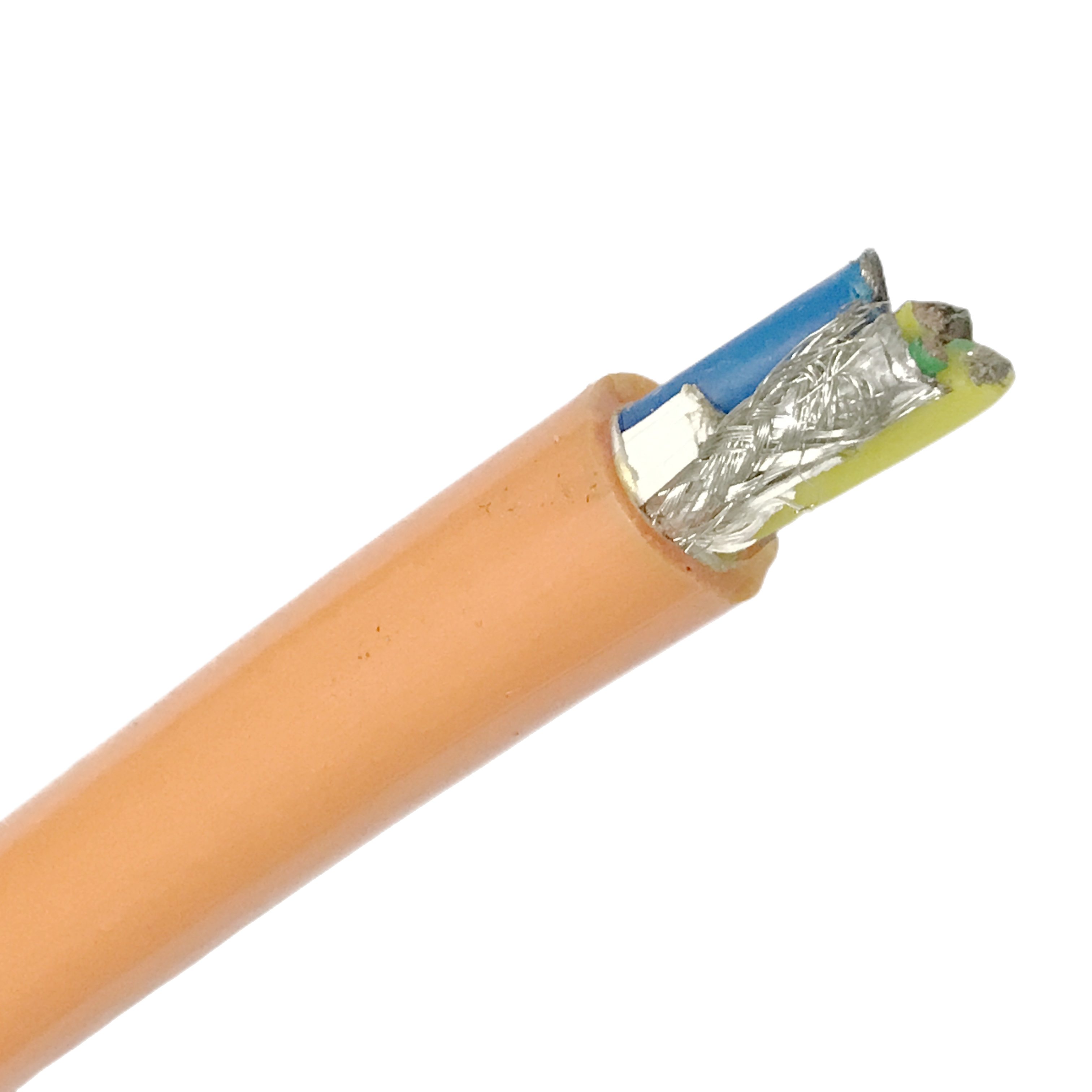
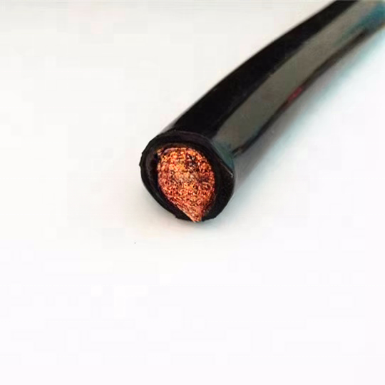
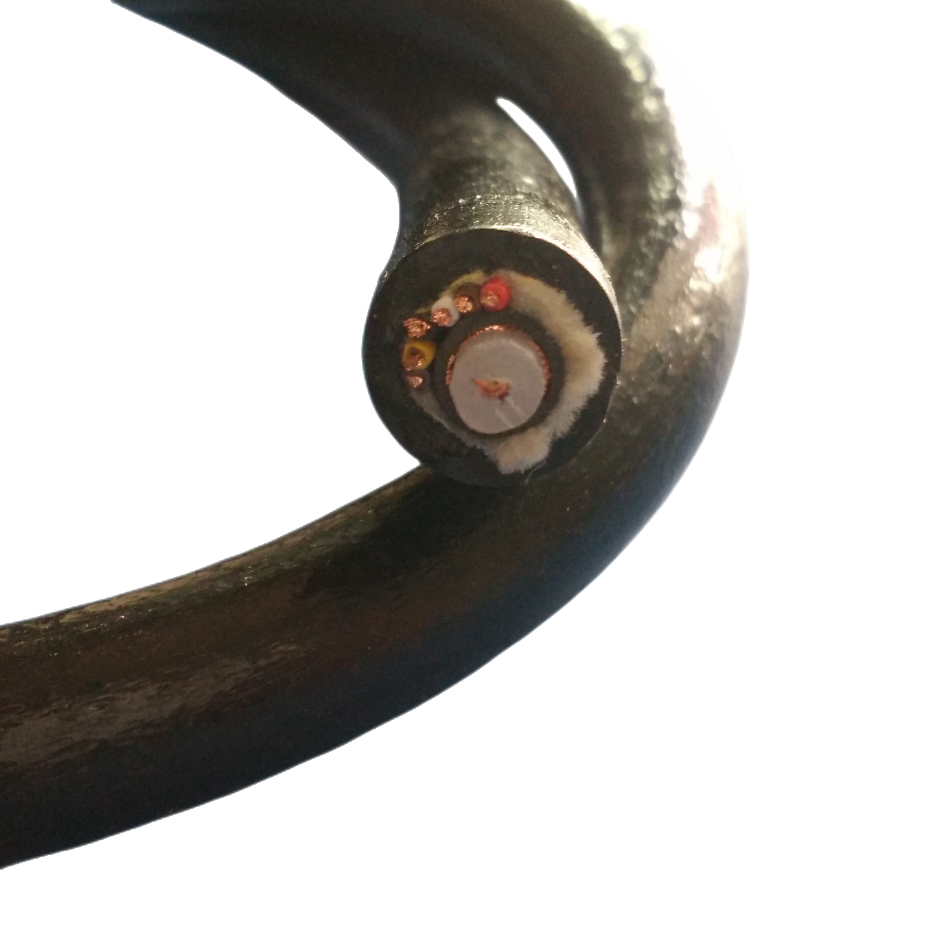
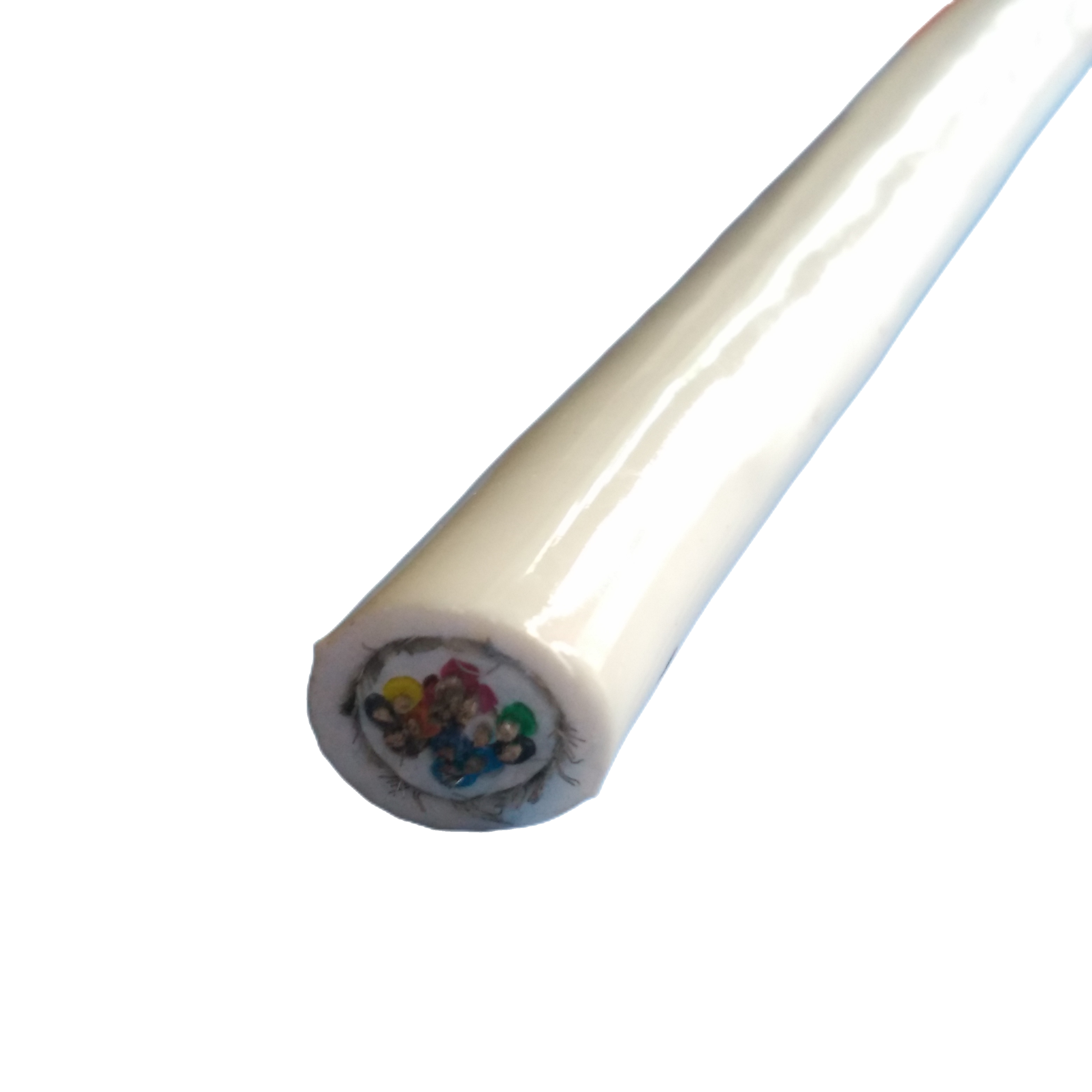
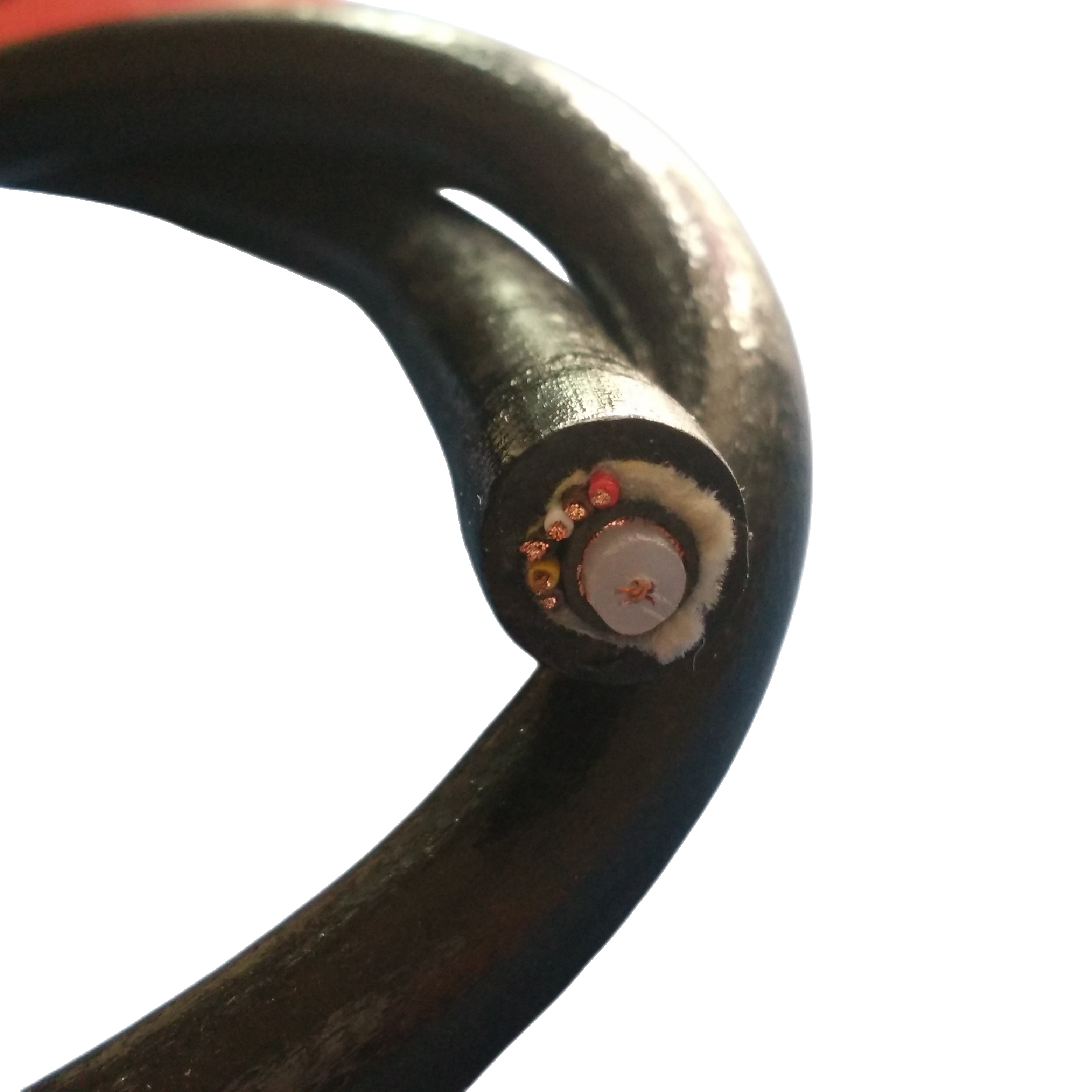
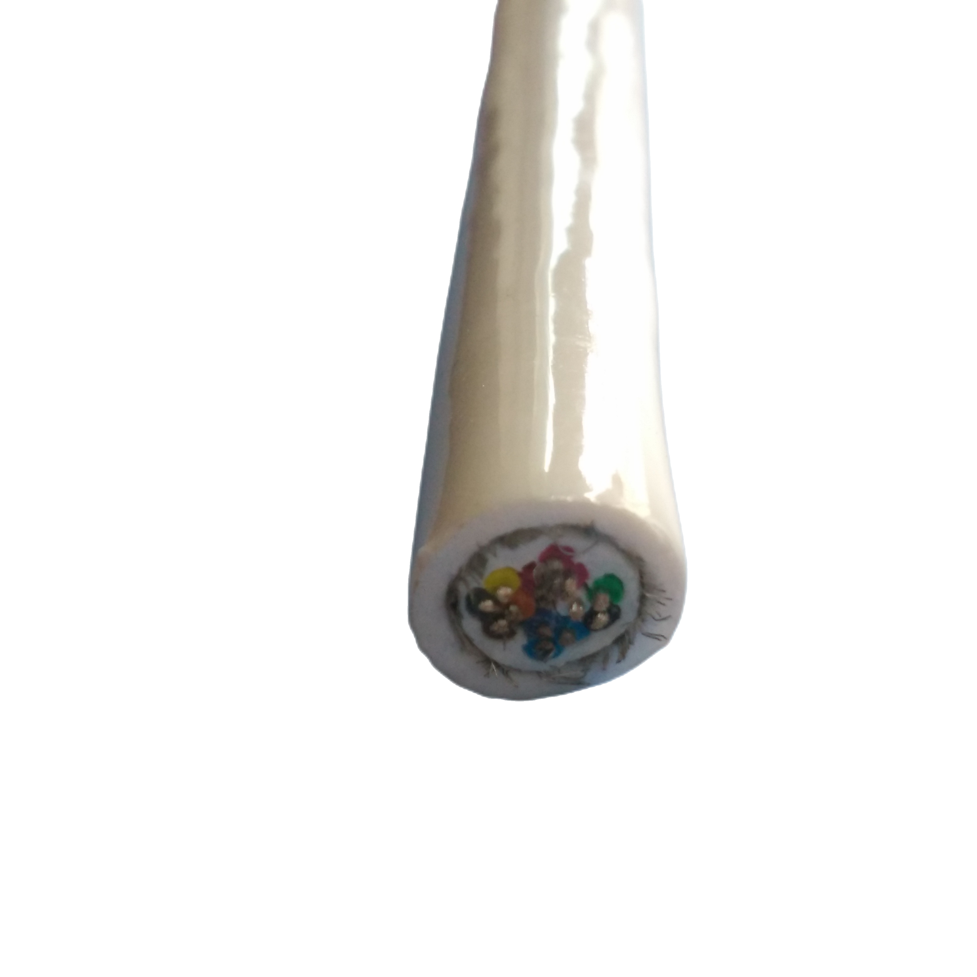
Construction — What Makes a Floating Cable Different
Floating fiber cable construction differs from all other subsea cable types in three fundamental ways: every material choice is made with density as a primary constraint alongside mechanical performance; the outer jacket must survive not just seawater immersion but prolonged UV exposure at the surface; and the mechanical design must tolerate the impulsive loading of wave action rather than the steady or slowly varying loads that govern subsea cable design.
|
Layer |
Material / Specification |
Why It Differs from Subsea Cable Construction |
|
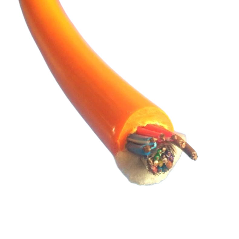
Optical fibre |
SM G.657.A1 or MM OM4. Gel-filled loose tube, PBT 0.4 mm wall (thinner than subsea grade to save mass). |
Thin-wall PBT tube reduces mass contribution. Gel fill is retained for water-blocking but tube wall is at minimum crush-rated thickness rather than the heavier subsea duty grade. The trade-off is accepted because floating cable does not experience hydrostatic crush pressure. |
|
Closed-cell foam core |
Extruded closed-cell polyethylene foam (crosslinked PE, density 0.05–0.12 g/cm³). Compressive strength: ≥0.3 MPa at 10% deformation. Water absorption: <1% by volume after 100 h immersion (ASTM D2842). |
The foam core has no equivalent in any subsea or drag chain cable. It is the buoyancy engine of the cable. Crosslinked PE foam is specified over polypropylene foam because its compressive strength is more temperature-stable: PP foam softens above +50°C (common on deck in tropical sun), losing buoyancy. XLPE foam maintains its cellular structure to +80°C. Foam density is calibrated per batch, not per specification range, to achieve ±0.02 g/cm³ cable density consistency. |
|
Kevlar tensile member |
Kevlar 29 (lower modulus, higher elongation than Kevlar 49). Parallel lay, single layer. Rating: 0.8–2.5 kN depending on model. Elongation at rated load: ≤2.5%. |
Kevlar 29 is used instead of the high-modulus Kevlar 49 specified in subsea tow cables: in a floating cable, the impulsive wave loads are dynamic and the cable needs to absorb energy elastically rather than behave as a rigid member. The higher elongation of Kevlar 29 (3.5% vs 2.4% for Kevlar 49 at break) provides a damping effect that reduces peak termination loads during wave impact. Kevlar 29 is also 15% lighter than Kevlar 49 per unit tensile strength, benefiting the buoyancy budget. |
|
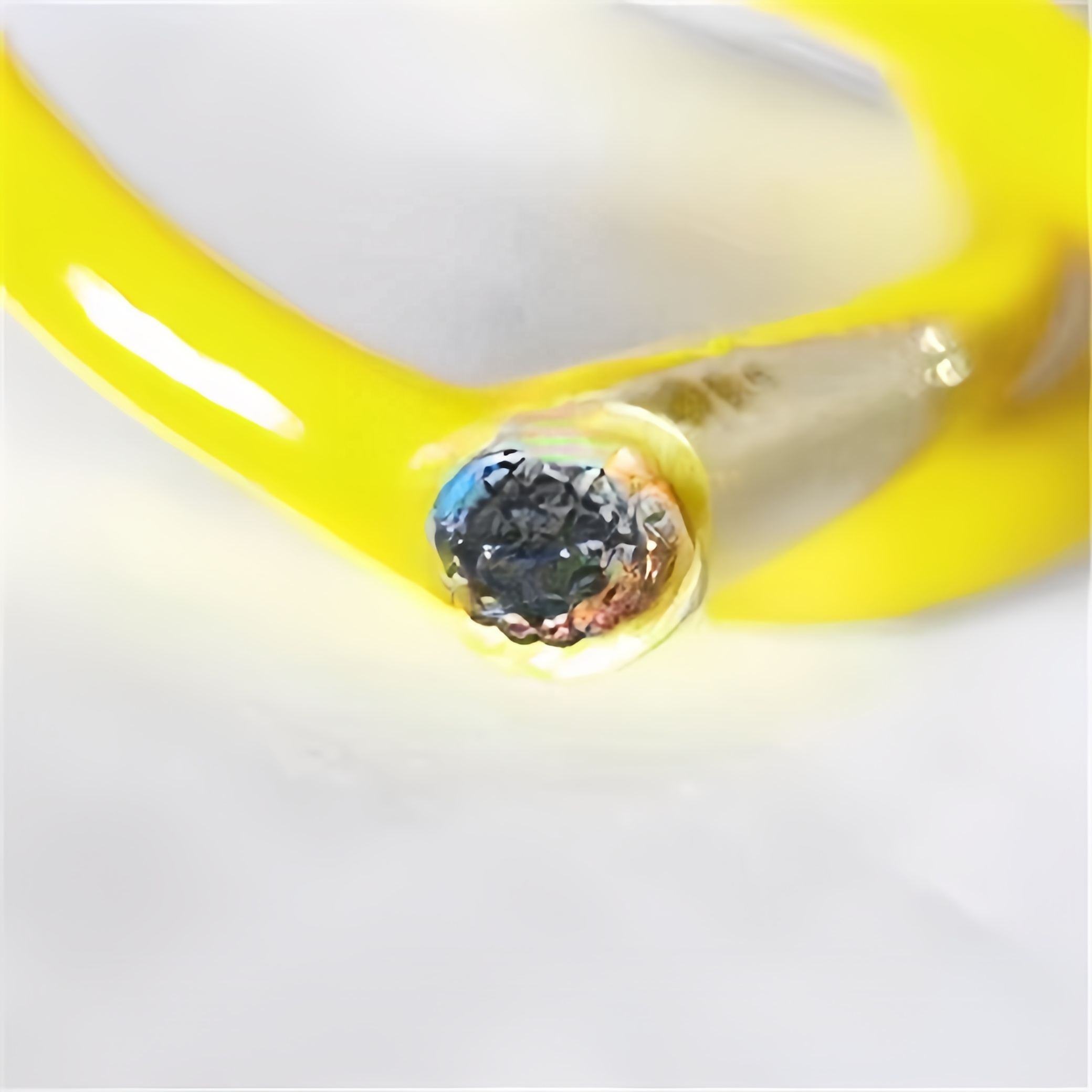
UV-stabilised outer jacket |
Polyether TPU with UV stabiliser package (HALS + UV absorber). Shore A 80±3. Tensile: ≥45 MPa. UV test: 2,000 h xenon arc (IEC 60811-401), ≤80% tensile retention. Black pigment optional for maximum UV stability. |
Subsea cables spend their service life below the UV penetration depth (~10 m) and do not require UV stabilisation. Floating cables are exposed to full-spectrum solar UV continuously, including UV-B (280–315 nm) which degrades unstabilised polyurethane within 6–12 months. The HALS (hindered amine light stabilizer) + UV absorber package provides 2,000 h xenon arc equivalent performance — roughly 10–15 years of outdoor surface exposure in tropical conditions. Shore A 80 (softer than subsea grades) is selected because wave-impact loading is impulsive and the softer compound absorbs energy through elastic deformation rather than transmitting peak load directly to the fibre bundle. |
|
Abrasion and boat contact layer (optional) |
High-abrasion TPU overjacket, Shore A 90, Taber ≥600 cycles. Applied as a second extruded layer over the UV jacket for cables that may contact vessel hulls, dock fenders, or rocky shore approaches. |
Floating cables near working harbours or shore approaches contact hulls, dock pilings, and rough surfaces. The abrasion overjacket is an optional additional layer — not standard on all models — that provides sacrificial wear resistance without compromising buoyancy significantly (+0.02 g/cm³ density impact). |
|
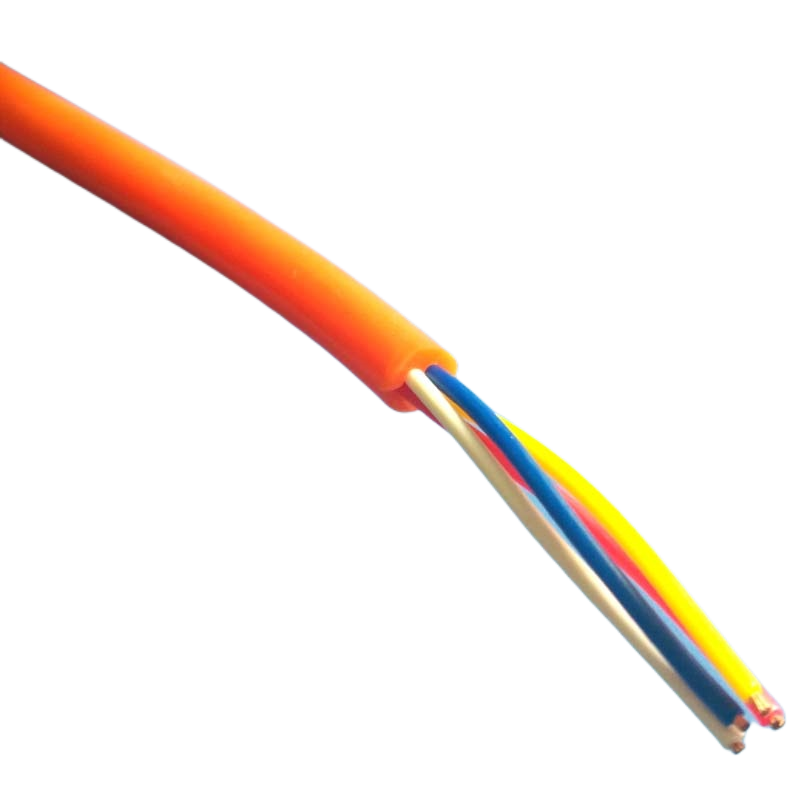
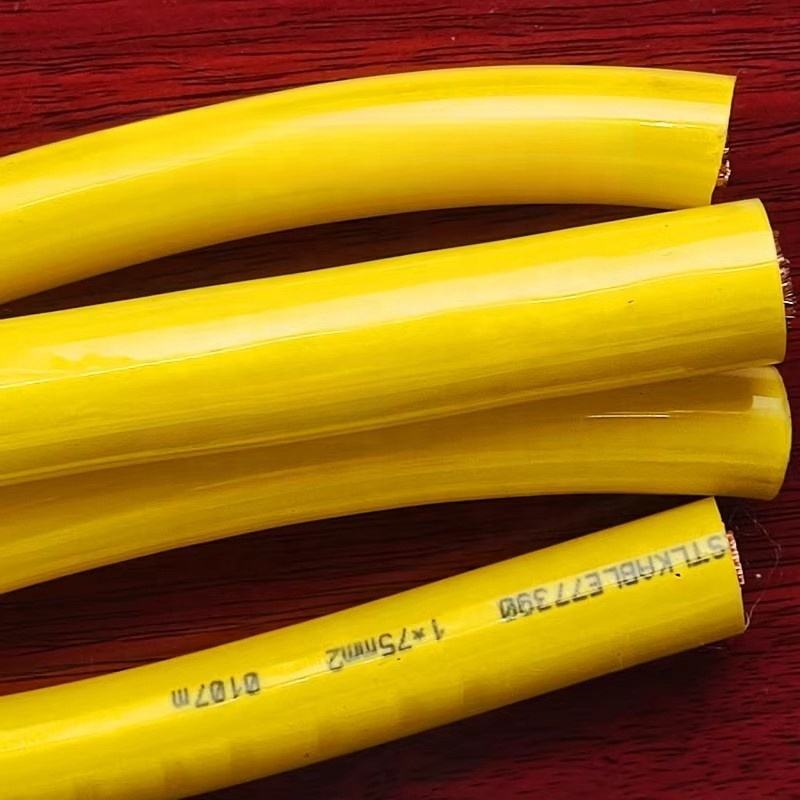
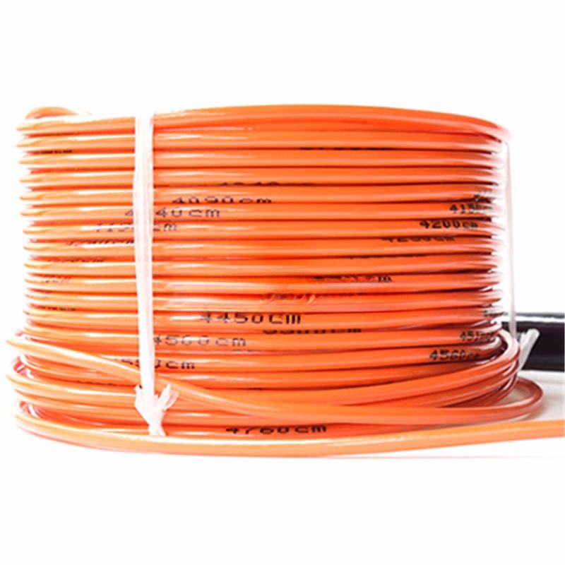
High-visibility jacket colour |
Standard: International Orange (RAL 2010) or Safety Yellow (RAL 1026). Custom: per order. Retro-reflective strip option: 25 mm retroreflective tape bonded to jacket surface at 1 m intervals. |
Subsea cables are typically black for UV stability. Floating cables must be visible to vessel operators. International Orange is the highest-contrast colour against blue-grey sea surface and is the international colour for marine safety equipment. Retroreflective strips make the cable visible at night from a vessel searchlight at up to 200 m range. |
Deployment Methods — From Vessel, RIB, and Shore
Floating fiber cable can be deployed from platforms that would be impractical for any other subsea cable type. Its positive buoyancy means it does not require a cable-laying vessel, an ROV, or diving support for most applications. The three primary deployment methods are described below with their operational parameters.
Method A — Vessel Trail Deployment
The cable drum is mounted on a deck reel on the paying-out vessel. The leading end is connected to the receiving platform (second vessel, shore station, or buoy) before departure. The paying-out vessel steams away from the receiving platform at a controlled speed (typically 2–4 knots) while the cable is paid out over the stern. The cable floats on the surface immediately behind the vessel.
|
Key parameters: Maximum pay-out speed: 5 knots (RST-FFC-4SM, 1.2 kN Kevlar). Pay-out tension must not exceed 40% of Kevlar rated load. Recommended deck reel brake tension: 5–10% of Kevlar rating to maintain control. Maximum single-leg run length without intermediate buoys: 500 m in sea state ≤4; 200 m in sea state 5. Common error: Allowing slack cable to accumulate astern during pay-out. Slack loops at the water surface are the primary cause of propeller-strike damage. Maintain positive brake tension throughout deployment. |
Method B — RIB (Rigid Inflatable Boat) Hand-Lay
For runs of up to 300 m in calm conditions (sea state ≤3), a crew member in a RIB can deploy the cable by hand from a reel mounted in the RIB or by flaking the cable into the RIB from a supply drum on the mothership. The cable is laid at the water surface as the RIB transits between the two endpoints. This method is the fastest deployment option and requires no specialised equipment beyond the RIB and a cable reel.
|
Key parameters: RIB transit speed during lay: 3–5 knots. Crew: minimum 2 persons (1 driving, 1 managing cable). Cable should be paid out from a reel, not thrown: aerial coils tangle and create permanent kink damage at the fibre bundle. Minimum RIB reel core diameter: 15× cable OD (RST-FFC-4SM: minimum reel core ≈ 250 mm diameter). Recovery: Pull cable hand-over-hand from the RIB as it transits back along the cable route. A floating cable in calm conditions can be recovered at up to 5 knots of RIB transit speed. Reel the recovered cable onto a drum immediately — do not leave it flaked on deck where foot traffic can cause fibre damage. |
Method C — Shore-to-Vessel or Shore-to-Buoy
The cable is paid out from a reel on shore (or from a vessel at the shore end) while the far end is taken out to the receiving platform by a RIB. The cable floats on the surface between the shore connection point and the platform. Shore-based reel stands should be positioned at least 5 m above high-water mark to prevent the reel from flooding during tidal surges.
|
Shore approach protection: At the point where the cable crosses the surf zone and beach, the cable must be protected against abrasion from sand, gravel, and rock. Use a UV-stable conduit (50 mm HDPE pipe minimum) buried 0.3 m below the beach surface and extending from the low-water mark to the shore-side termination point. The RST-FFC-A abrasion overjacket option adds Taber ≥600 cycles protection for cables that cannot be conduit-protected. High-visibility marking: At the shoreline crossing, mark the cable entry/exit points with orange hazard posts (1.2 m height minimum) and a CABLE IN USE — DO NOT ANCHOR sign visible from the water. |
Technical Parameters
Optical Performance — SM G.657.A1
|
Parameter |
Specification |
Standard |
|
Attenuation @ 1,310 nm |
≤0.36 dB/km |
IEC 60793-2-50 |
|
Attenuation @ 1,550 nm |
≤0.20 dB/km |
IEC 60793-2-50 |
|
Additional attenuation: wave-action bending (1,000 cycles at 10× OD) |
≤0.03 dB/km |
IEC 60794-1-2 Method E10 |
|
Additional attenuation: solar UV exposure (2,000 h xenon arc) |
≤0.01 dB/km |
IEC 60811-401 + OTDR re-test |
|
Chromatic dispersion @ 1,550 nm |
≤17 ps/(nm·km) |
IEC 60793-2-50 |
|
PMD |
≤0.04 ps/√km |
IEC 60793-2-50 |
|
Min bend radius (dynamic, G.657.A1) |
≥10 mm |
IEC 60793-2-50 |
|
OTDR trace supplied |
Yes: 1,310 + 1,550 nm, per fibre, per drum, .SOR format |
Factory measurement |
Buoyancy & Mechanical
|
Parameter |
Value |
Test / Reference |
|
Cable density (all models) |
0.85–0.92 g/cm³ (floating); 1.00±0.01 (NB model) |
Per-drum buoyancy immersion test; certificate included |
|
Net buoyancy in seawater (1.025 g/cm³) |
+50 to +62 N per 100 m (model-dependent) |
Calculated from measured cable density; verified by immersion test |
|
Net buoyancy in fresh water (1.000 g/cm³) |
+30 to +48 N per 100 m |
Calculated |
|
Tensile rating (Kevlar 29) |
0.8–2.5 kN (model-dependent); tested to 1.5× rated load |
ASTM D7269; load-cell certified per drum |
|
Maximum deployment speed |
5 knots (trail deployment); 3 knots (RIB hand-lay) |
Operational guideline; based on drag-load vs Kevlar capacity |
|
Minimum deck reel core diameter |
15× cable OD (standard dynamic handling) |
Kevlar 29 fatigue preservation guideline |
|
Operating temperature |
−20°C to +70°C (surface air); −5°C to +35°C (seawater) |
IEC 60811-501 |
|
Foam compression set (XLPE, 50% deformation, 24 h) |
≤5% (no permanent buoyancy loss) |
ASTM D1056 |
|
Foam water absorption |
<1% by volume after 100 h immersion |
ASTM D2842 |
|
UV resistance (jacket) |
2,000 h xenon arc; ≤20% tensile loss |
IEC 60811-401 |
|
Jacket colour (standard) |
International Orange RAL 2010 or Safety Yellow RAL 1026 |
— |
|
Retroreflective strip option |
25 mm 3M Scotchlite at 1 m intervals; visible to 200 m at night |
SOLAS Reg. II-1/3-4 retroreflective standard |
|
Jacket abrasion (standard) |
≥350 cycles Taber CS-17, 1 kg |
ISO 9352 |
|
Jacket abrasion (A variant overjacket) |
≥600 cycles |
ISO 9352 |
|
Minimum breaking strength (MBS) cable assembly |
3.5× Kevlar rated load (includes jacket and fibre tube contribution) |
IEC 60794-1-2 Method E1 |
|
Recovery by hand from RIB |
Yes — positive buoyancy allows hand-over-hand surface recovery |
Operational capability; verified in field trials |
Field Deployment References
Customer identities withheld at client request. Optical data measured with customer’s OTDR equipment in operational conditions.
|
Project |
Operation |
RST-FFC Model |
Challenge |
Result & Duration |
|
Naval exercises, Western Pacific |
Secure fiber comms between two frigates in formation, 400 m spacing, 4-day exercise, sea state 0–3 |
RST-FFC-8SM, 450 m, International Orange jacket, retroreflective strips |
Previous copper cable could not provide the 1 Gbit/s link speed needed for encrypted video conferencing between command teams. RST-FFC-8SM with 1000BASE-LX SFPs achieved <1 ms latency. Cable recovered between exercise phases and redeployed 4 times without attenuation change. |
4-day exercise completed. Cable OTDR showed 0.22 dB/km post-exercise, vs 0.21 dB/km pre-deployment. Adopted for fleet exercise protocol. |
|
Marine research station, Norwegian coast |
Floating fiber link between coastal research station and offshore instrument buoy, 220 m, permanent installation, tidal zone |
RST-FFC-4SM, 250 m, with abrasion overjacket (A variant) for shore crossing |
Cable subject to daily tidal current reversal of 1.5–2.0 kts. Previous polychloroprene floating cable developed jacket fatigue cracks at shore crossing within 8 months from sand abrasion. RST-FFC-4SM with A overjacket: 18 months without jacket breach. |
18 months service (2023–2024). Cable in service. Annual OTDR: 0.22 dB/km stable. |
|
Offshore drilling support, Gulf of Mexico |
Temporary 850 m fiber link between drillship and platform supply vessel during simultaneous operations, 3-week duration |
RST-FFC-12SM, 900 m total, with intermediate buoy floats every 100 m |
Operations in sea state 3–4. Standard 450 m single-span would have exceeded safe termination load. 100 m intermediate buoys divided load into 9 × 100 m spans; peak termination load <8% of Kevlar rating at sea state 4. |
3-week operation completed. No optical performance issues. Cable recovered and returned to stock. |
|
Disaster relief operation, Indian Ocean |
Emergency shore comms link after subsea cable damage, coastal to offshore vessel, 600 m, rapid deployment |
RST-FFC-4SM, 650 m, deployed from RIB in 22 minutes by 2-person team |
No vessel-mounted cable-laying equipment available. RIB hand-lay method used. Cable operational within 35 minutes of arrival on-scene. 1000BASE-LX link at 1 Gbit/s provided satellite gateway uplink until permanent cable was repaired. |
6-day deployment. Cable recovered manually by RIB team. |
|
Aquaculture monitoring array, Scottish Highlands |
Floating fiber link between 6 salmon cage monitoring buoys, fresh-water loch, 400 m total array, permanent |
RST-FFC-NB (near-neutral buoyancy for fresh water), 4×SM, 420 m total |
Loch fresh water density is 1.000 g/cm³. Standard RST-FFC positive buoyancy in seawater would give excessive freeboard in fresh water, making cable vulnerable to wind drag. RST-FFC-NB tuned to 1.00±0.01 g/cm³ lies just at the surface in fresh water without freeboard. |
Deployed 2023. 2-year planned deployment. Year-1 OTDR check: 0.20 dB/km, stable. |
FAQ — Marine Operators & Procurement Teams
Q1: Will the foam core lose buoyancy over time as the cable ages?
Crosslinked PE (XLPE) closed-cell foam does not absorb water and does not undergo creep under sustained compression at the load levels experienced by a floating cable. The primary aging mechanism for foam buoyancy is UV degradation of the foam-jacket interface, which can allow the foam to delaminate from the jacket and allow water to enter the foam layer — but this is prevented in RST-FFC by the UV-stabilised jacket compound that bonds to the foam without creating a void interface. Our accelerated aging test (2,000 h xenon arc equivalent) shows foam buoyancy retention >97% after the equivalent of 10–15 years of tropical surface exposure. For deployments longer than 5 years, we recommend an annual visual inspection of the jacket surface and a per-drum buoyancy test if the cable is recovered for maintenance.
Q2: Can a floating fiber cable be run through the water alongside a vessel underway, for example as a towed sensor tether?
Yes, within speed limits. The drag force on a floating cable at the water surface is significantly lower than on a submerged cable because approximately 20–30% of the cable cross-section is above the waterline and not subject to hydrodynamic drag. At 3 knots, a 100 m RST-FFC-4SM run alongside a vessel experiences approximately 0.12 kN of drag load — well within the 1.2 kN Kevlar rating. At 5 knots, drag increases to approximately 0.35 kN, still within the 40% operational limit (0.48 kN) recommended to preserve Kevlar fatigue life. Above 6 knots, we recommend switching to the RST-FFC-12SM (2.5 kN Kevlar) or consulting our engineering team for a drag-load calculation specific to your vessel and cable geometry.
Q3: What is the minimum radius for coiling and storing a floating fiber cable?
The minimum coil radius for RST-FFC cables is 15× cable OD — the same as the deck reel core diameter recommendation. For RST-FFC-4SM (OD 16.5 mm), this is a minimum coil radius of 248 mm (approximately 500 mm diameter drum). The foam core is the limiting element, not the fibre: foam compressed below 10× OD radius develops a permanent set that slightly increases cable stiffness at the coil point, though this does not affect fibre performance. When coiling cable on deck for storage, use an open spool or create a figure-8 coil (not a simple round coil) for cable lengths over 50 m — figure-8 coiling eliminates torsional twist that accumulates in round coils and can cause the cable to tangle during the next deployment.
Q4: How is the cable terminated at a shipboard or buoy end?
RST-FFC cables terminate in the same way as any other fiber optic cable: a cable gland provides jacket strain relief and waterproofing at the equipment enclosure entry; fibre pigtails (factory-fusion-spliced) connect the cable fibres to the equipment patch panel or SFP transceiver cage; and the Kevlar tensile member is clamped at the cable grip inside the gland body. The critical difference from subsea cable termination is that the tensile member clamp must accommodate the dynamic impulsive loading from wave action — we specify a Kellems grip (woven wire pulling grip) with a stainless shackle rather than a simple jam cleat. For the far end at a buoy, the cable gland is rated to IP68 (1 m, 30 min per IEC 60529) and the cable entry angle is controlled by a fairlead to prevent bending below 10× OD at the termination point.
Q5: What is the difference between the RST-FFC and RST-UTC neutral buoyancy umbilical?
Both cables achieve near-neutral or slight positive buoyancy, but they are designed for different operating environments and mechanical loading profiles. RST-UTC-NB is designed for underwater deployment (down to 500 m depth) and carries Kevlar tensile members rated for subsea towing loads; its jacket is formulated for hydrostatic pressure resistance and is not UV-stabilised for surface exposure. RST-FFC-NB is designed for surface and near-surface deployment and carries Kevlar 29 (higher elongation, lower modulus) for absorbing wave-impact loads; its UV-stabilised jacket is designed for prolonged surface exposure but is not tested for hydrostatic pressure. The crosslinked PE foam in RST-FFC-NB would be crushed and lose buoyancy at depths greater than ~30 m. Do not use RST-FFC for subsea depths or RST-UTC-NB for long-duration surface UV exposure.
Q6: How do I prevent other vessels from running over the cable?
Three measures are used in combination. First, colour: International Orange jacket or Safety Yellow jacket is the highest-contrast colour combination against a sea surface and is the standard colour for marine safety equipment internationally. Second, retroreflective strips: 25 mm 3M Scotchlite strips at 1 m intervals make the cable visible at night from a vessel searchlight at up to 200 m range — sufficient response distance at vessel speeds below 5 knots. Third, marking buoys: for runs in commercial traffic areas, attach a surface marker buoy (SMB) at each end and at every 100 m midpoint. SMBs should display a yellow ‘X’ flag (cable operations flag under COLREGS) and a white flashing light at night. These measures do not provide absolute protection — floating cable in commercial anchorages or shipping channels is inherently at risk from vessel traffic and should only be deployed with appropriate vessel traffic management in place.
Manufacturer Background — Shanghai Rousheng
|
Floating cable production capabilities Closed-cell XLPE foam extrusion line: density calibrated per batch to ±0.02 g/cm³ Per-drum buoyancy immersion test in fresh water and seawater tanks; certificate issued UV weatherometer: 2,000 h xenon arc per IEC 60811-401 OTDR suite: 1,310 + 1,550 nm SM; 850 nm MM; .SOR archive 10 years Kevlar tensile testing to 1.5× rated load; load-cell certificate per drum High-visibility jacket pigment: colour verified against RAL 2010 / RAL 1026 reference Retroreflective strip bonding: peel-strength tested per ASTM D903 |
Certifications ISO 9001:2015 quality management system CE marking — LVD Directive 2014/35/EU RoHS 2 / REACH SVHC declaration per shipment SOLAS Reg. II-1/3-4 retroreflective compliance (retroreflective strip option) CNAS-accredited lab reports on request DNV / Bureau Veritas type approval on request Buoyancy test certificate: per drum, fresh water + seawater |
Rousheng’s floating cable engineering team maintains a database of sea-state performance measurements from RST-FFC field deployments across five ocean regions. When customers provide their deployment geography and typical sea-state profile, we compare their application against the nearest field reference to confirm model selection before order placement. This pre-sale validation is provided at no charge and is documented in writing.
Request a Quote, Sample, or Deployment Consultation
|
Contact Email: Jerry@rstlkable.com Phone: +86-021-50759965 Mobile: +86-13482197396 Address: No. 2591 Fengzhe Road, Fengxian District, Shanghai, China Quote within 24 hours. Buoyancy test certificate, OTDR trace, and Kevlar load certificate included with every drum. |
Include in your enquiry 1. Deployment environment: seawater or fresh water 2. Cable run length and configuration (ship-to-ship, shore-to-buoy, etc.) 3. Fibre count and data protocol (1000BASE-LX, EtherCAT, etc.) 4. Typical sea state at deployment location 5. Deployment method (vessel trail, RIB hand-lay, shore-to-vessel) 6. Duration (temporary exercise, seasonal, or permanent) We provide a sea-state validation, buoyancy force calculation, and termination load estimate with every technical enquiry. |