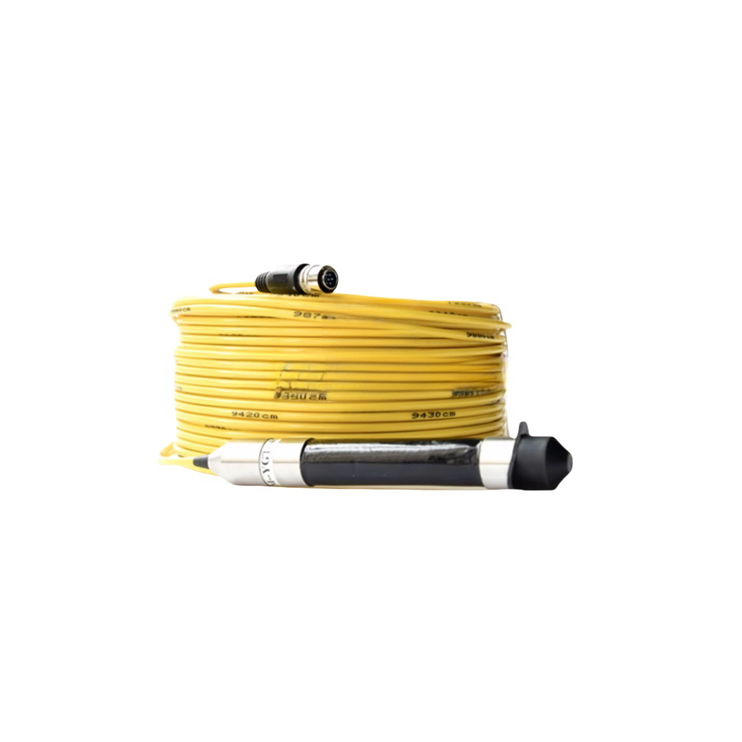
Ethernet + Power Hybrid Cable | Combined Data and Power Cable for Industrial Automation & Marine Equipment
The RST-EPC Series Ethernet and power hybrid cable combines Cat 5e, Cat 6, or Cat 6A individually screened twisted pairs with OFC power cores (1.5–4.0 mm², 300/500 V or 0.6/1 kV) in a single polyether TPU or marine PUR jacket. Three-tier EMI shielding delivers ≥58 dB power-to-data coupling attenuation — validated at 100 Mbit/s PROFINET IRT with 32 A power load. Available in 10 standard models including drag chain flex, 3-phase, dual Ethernet, and marine variants. CE, RoHS 2, ISO 9001 certified.
Ethernet + Power Hybrid Cable | Combined Data and Power Cable for Industrial Automation & Marine Equipment
Home › Products › Industrial Hybrid Cables › Ethernet + Power Cable │ Series: RST-EPC │ Reviewed by: Rousheng Industrial Cable Engineering Team
|
⚡ Power channel Up to 4 × 4.0 mm² OFC conductors Rated: 300/500 V or 0.6/1 kV Current: up to 32 A per core (derated in composite) Insulation: XLPE, +90°C conductor temp Suitable for VFD, servo, 24 VDC supply rails |
7 Data channel Cat 5e to Cat 6A twisted pairs (1 or 2 pairs) 100 Mbit/s to 10 Gbit/s per pair Individual foil screen + overall Cu braid Protocols: EtherCAT, PROFINET, Modbus TCP, 1000BASE-T Impedance: 100 Ω ±5 Ω per pair |
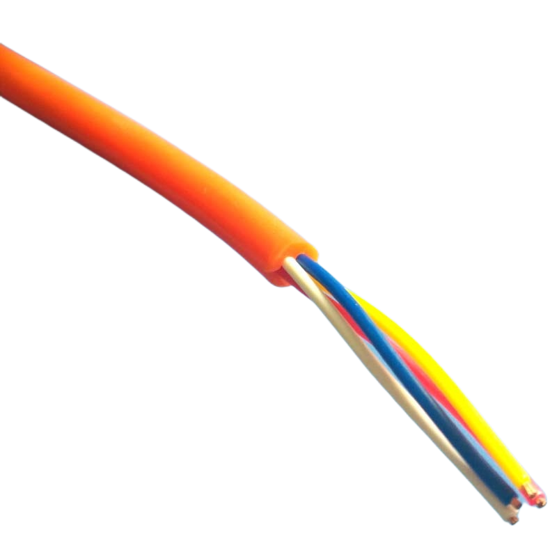
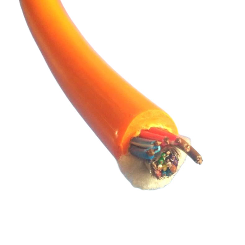
Ethernet and power hybrid cable combines a high-speed industrial Ethernet data path with copper power conductors inside a single flexible jacket — eliminating the separate cable runs that otherwise compete for space in cable carriers, trunking, and conduit entries across the full width of modern automation infrastructure.
The RST-EPC series is engineered for two distinct markets that share the same core problem. In industrial automation, servo drives, I/O nodes, and camera systems all need network connectivity alongside 24 VDC or 400 VAC supply. In marine equipment, deck instruments, thruster controllers, and monitoring nodes need Ethernet alongside power — in a single cable entry through a watertight gland.
The single-cable entry advantage
Every cable penetration through a control cabinet wall, a junction box, or a ship’s bulkhead is a potential ingress point for water, dust, and EMI. Reducing two cable glands to one — by using a hybrid cable — halves the number of potential failure points at every junction box in the system. In IP67 or IP69K enclosures, this is not a convenience: it is a reliability-engineering decision.
Page Contents
- Technology Comparison: Hybrid Cable vs. PoE vs. Separate Cables
- Model Range & Specifications
- Protocol × Power Rating Compatibility Grid
- Construction — Layer by Layer
- EMI Isolation: How Power and Data Coexist
- Installation Compliance Reference
- Technical Parameters
- Project References
- FAQ — Automation Engineers & Marine System Integrators
- Manufacturer Credentials
- Request a Quote
Technology Comparison: Hybrid Cable vs. PoE vs. Separate Cables
Why PoE alone is not always enough
Power over Ethernet (PoE) delivers up to 90 W per port (IEEE 802.3bt PoE++) through the data pairs themselves. This is sufficient for IP cameras, access points, and small sensors. However, PoE has hard limits: 90 W maximum, 100 m maximum run length at 1 Gbit/s, and no path for 3-phase or 24 VDC motor power alongside the data signal. When the powered device exceeds 90 W or requires a separate power rail voltage, PoE is ruled out.
The correct technology for each power level
|
Power Requirement |
PoE / PoE+ / PoE++ |
Power-over-Coax |
RST-EPC Hybrid Cable |
|
< 15 W (IP camera, sensor) |
PoE (IEEE 802.3af) — preferred |
Not applicable |
Not needed |
|
15–60 W (PTZ camera, thin client) |
PoE+ (IEEE 802.3at) — preferred |
Possible |
Not needed |
|
60–90 W (AP, small display) |
PoE++ (IEEE 802.3bt) — preferred |
Alternative |
Optional |
|
90–500 W (servo I/O node, small drive) |
Not possible — PoE limit exceeded |
Limited to ~120 W |
RST-EPC preferred |
|
0.5–5 kW (servo drive, motor, heater) |
Not possible |
Not possible |
RST-EPC required |
|
3-phase 400 VAC alongside Ethernet |
Not possible |
Not possible |
RST-EPC (3× core model) |
|
>100 m run at 1 Gbit/s |
Not possible — copper limit |
Not possible |
RST-EPC + fiber SFP uplink |
RST-EPC is the correct choice when: power exceeds 90 W per device, run length exceeds 100 m, voltage is not 48 VDC, or 3-phase supply is needed alongside Ethernet. Below these thresholds, PoE is simpler and lower cost.
Hybrid cable vs. running two separate cables
|
Installation saving: In a factory with 120 servo I/O nodes, each requiring one Cat 5e cable and one power cable: that is 240 cable runs through the cable management system. RST-EPC reduces this to 120 runs — one per node. In a study of automotive assembly line retrofits, this reduction cut cable installation labour by 28% and reduced cable carrier fill ratio from 74% to 42%. Fault density: Each cable termination is a potential failure point. Halving the cable count halves the termination count and the associated fault probability. In marine applications where connector access requires a confined-space entry, this is an operationally significant safety improvement. |
RST-EPC Series — Model Specifications
|
Model |
Ethernet Pairs |
Power Cores |
Voltage |
OD |
Shield |
Jacket |
Primary Application |
|
RST-EPC-C5-2P |
1× Cat 5e (2 pairs) |
2×1.5 mm² OFC |
300/500 V |
10.8 mm |
Individual foil + overall braid |
PVC flex |
24 VDC sensor supply + 100 Mbit/s Ethernet |
|
RST-EPC-C5-4P |
1× Cat 5e (2 pairs) |
4×1.5 mm² OFC |
300/500 V |
13.2 mm |
Individual foil + overall braid |
TPU |
PLC I/O node, servo power + EtherCAT |
|
RST-EPC-C6-4P |
1× Cat 6 (2 pairs, 250 MHz) |
4×2.5 mm² OFC |
300/500 V |
15.6 mm |
Individual foil + overall braid |
TPU |
High-speed camera node, 1 Gbit/s + 24 VDC |
|
RST-EPC-C6A-4P |
1× Cat 6A (4 pairs, 500 MHz) |
4×2.5 mm² OFC |
300/500 V |
18.4 mm |
Individual foil + overall braid |
TPU |
10 Gbit/s backbone + servo power, data centre edge |
|
RST-EPC-2E-4P |
2× Cat 5e (4 pairs total) |
4×1.5 mm² OFC |
300/500 V |
16.2 mm |
Per-pair foil + overall braid |
TPU |
Dual Ethernet (daisy chain), 2-port PROFINET node |
|
RST-EPC-3PH-C5 |
1× Cat 5e (2 pairs) |
3×4.0 mm² + PE |
0.6/1 kV |
19.0 mm |
Individual foil + overall braid |
TPU |
3-phase motor drive + EtherCAT network, crane |
|
RST-EPC-MAR-C5 |
1× Cat 5e (2 pairs) |
4×2.5 mm² OFC |
300/500 V |
14.8 mm |
Individual foil + overall braid |
Marine PUR |
Marine deck instrument, offshore SCADA node |
|
RST-EPC-MAR-C6 |
1× Cat 6 (2 pairs) |
4×4.0 mm² OFC |
0.6/1 kV |
18.2 mm |
Individual foil + overall braid |
Marine PUR |
Offshore wind turbine controller, subsea junction |
|
RST-EPC-FLX-C5 |
1× Cat 5e (2 pairs) |
4×1.5 mm² OFC |
300/500 V |
13.6 mm |
Individual foil + overall braid |
TPU |
Drag chain, robotic arm: ≥5 M flex cycles rated |
|
RST-EPC-OEM |
1–2× Cat 5e/6/6A |
Per spec |
Per spec |
Per spec |
Per spec |
Per spec |
Custom: automotive OEM, offshore, rail, defence |
OD tolerance: ±0.3 mm. TPU jacket = polyether grade, oil and flex rated. Marine PUR = UV-stabilised polyether PUR, 5,000 h seawater immersion tested. FLX = high-flex drag chain variant, dynamic bend radius 7.5× OD. Cat 6A = S/FTP (individual foil per pair + overall braid).
Protocol × Power Rating Compatibility
The Ethernet pair specification in a hybrid cable must match the protocol running on the network, not just the nominal ‘Cat 5e’ or ‘Cat 6’ label. The table below maps each industrial Ethernet protocol to its minimum pair requirement and confirms which RST-EPC model carries both the data and the power level needed for each application.
|
Protocol |
Standard |
Max Data Rate |
Power in Same Cable |
Typical RST-EPC Model |
|
EtherCAT |
IEC 61158 Type 12 |
100 Mbit/s |
24 VDC control + 230 VAC servo |
RST-EPC-C5-4P or RST-EPC-3PH-C5 |
|
PROFINET RT |
IEC 61158 Type 10 |
100 Mbit/s |
24 VDC I/O node supply |
RST-EPC-C5-4P or RST-EPC-2E-4P |
|
PROFINET IRT (Class 3) |
IEC 61158 Type 10 |
100 Mbit/s (hard real-time) |
24 VDC + 48 VDC hybrid |
RST-EPC-C5-4P (IRT-compliant pair) |
|
Modbus TCP |
IEEE 802.3 (1000BASE-T) |
1,000 Mbit/s |
Any DC or AC supply |
RST-EPC-C6-4P |
|
EtherNet/IP |
ODVA CIP |
100 Mbit/s or 1 Gbit/s |
24 VDC panel supply |
RST-EPC-C5-4P or RST-EPC-C6-4P |
|
CC-Link IE Field Basic |
CC-Link Partner Association |
1,000 Mbit/s |
24 VDC |
RST-EPC-C6-4P |
|
1000BASE-T (SCADA/HMI) |
IEEE 802.3 |
1,000 Mbit/s |
120/230 VAC single phase |
RST-EPC-C6-4P |
|
10GBASE-T (backbone) |
IEEE 802.3an |
10,000 Mbit/s |
Server rack 230 VAC |
RST-EPC-C6A-4P |
|
Marine NMEA 2000 |
IEC 61162-3 |
250 kbit/s (CAN-based) |
12 VDC or 24 VDC vessel supply |
RST-EPC-MAR-C5 |
|
IEC 61850 (substation) |
IEC 61850-8-1 |
100 Mbit/s |
110/220 VDC substation bus |
RST-EPC-MAR-C6 |
IRT = Isochronous Real-Time, requires jitter <1 μs; RST-EPC-C5-4P Cat 5e pairs are validated for PROFINET IRT with propagation delay ≤5.1 ns/m. 10GBASE-T requires Cat 6A (500 MHz) — do not use Cat 5e or Cat 6 for 10 Gbit/s runs.
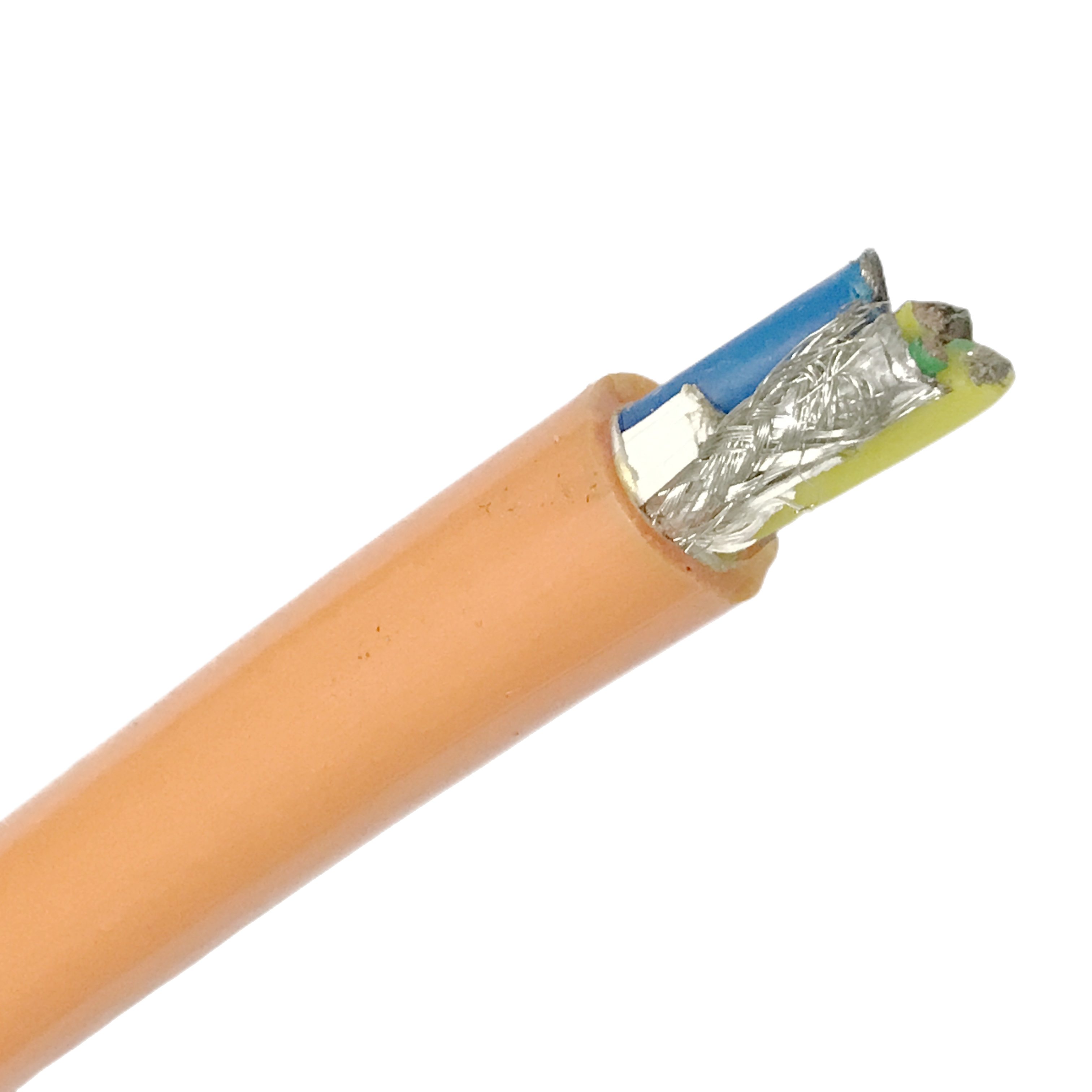
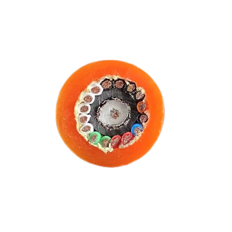
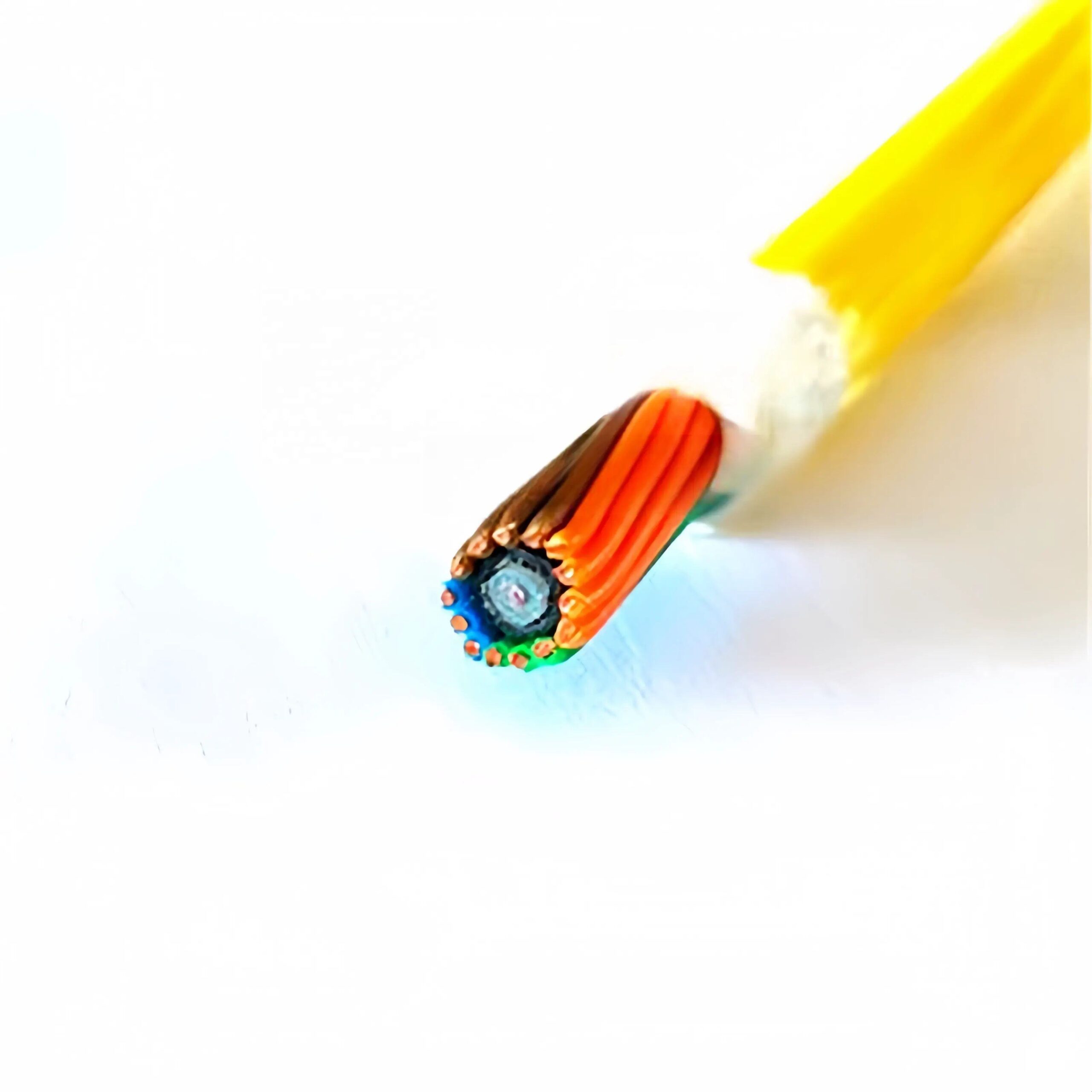
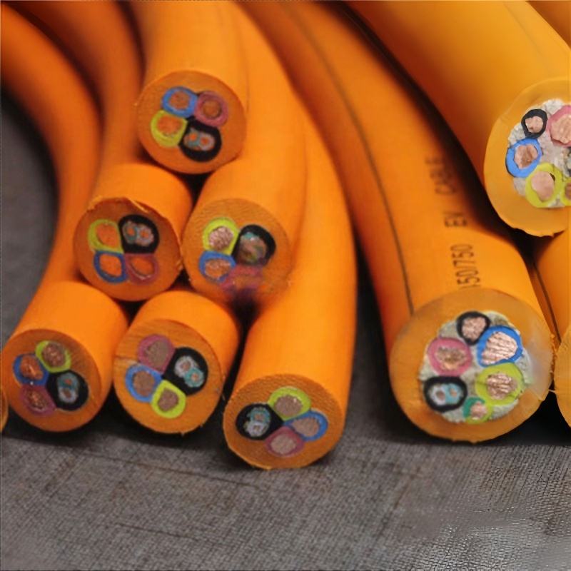
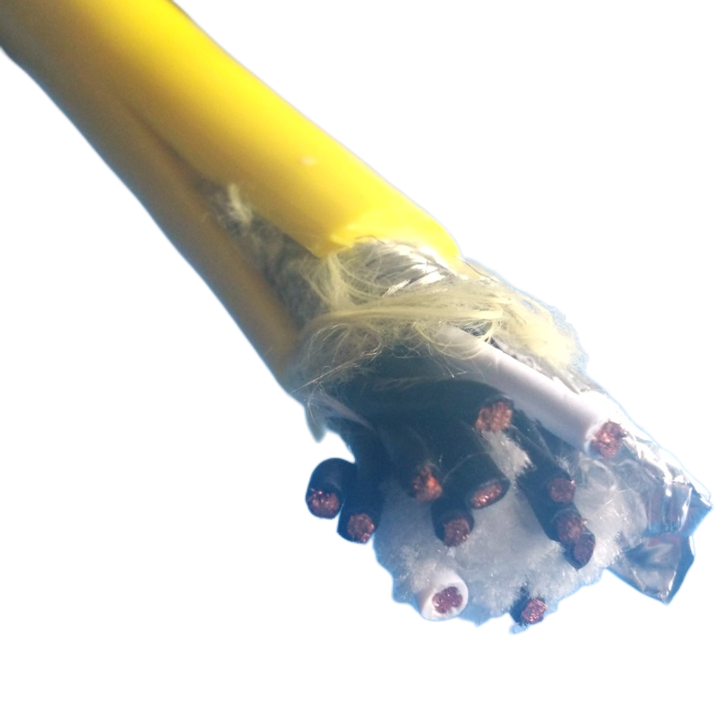
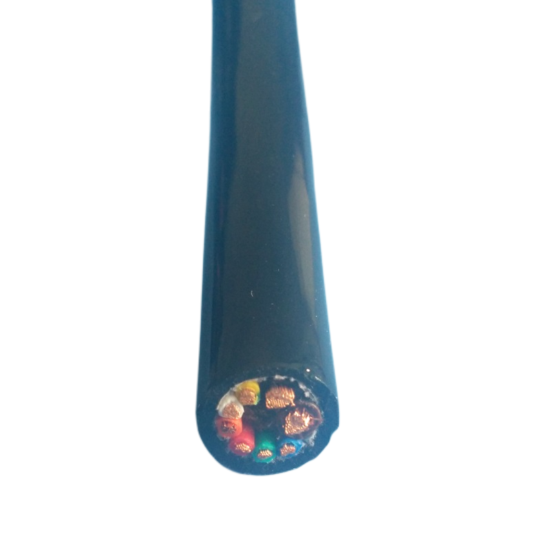
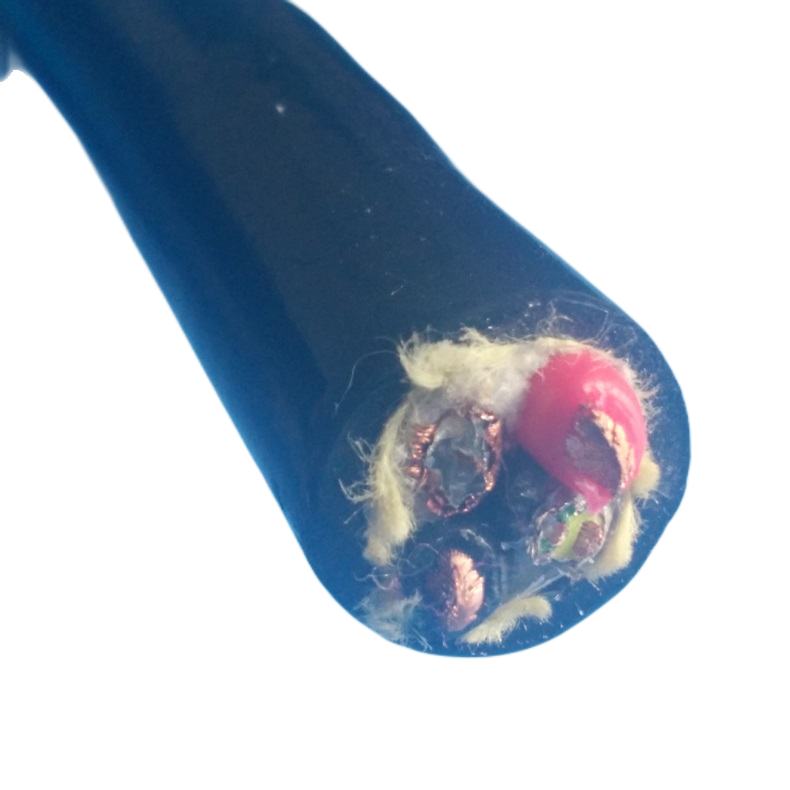
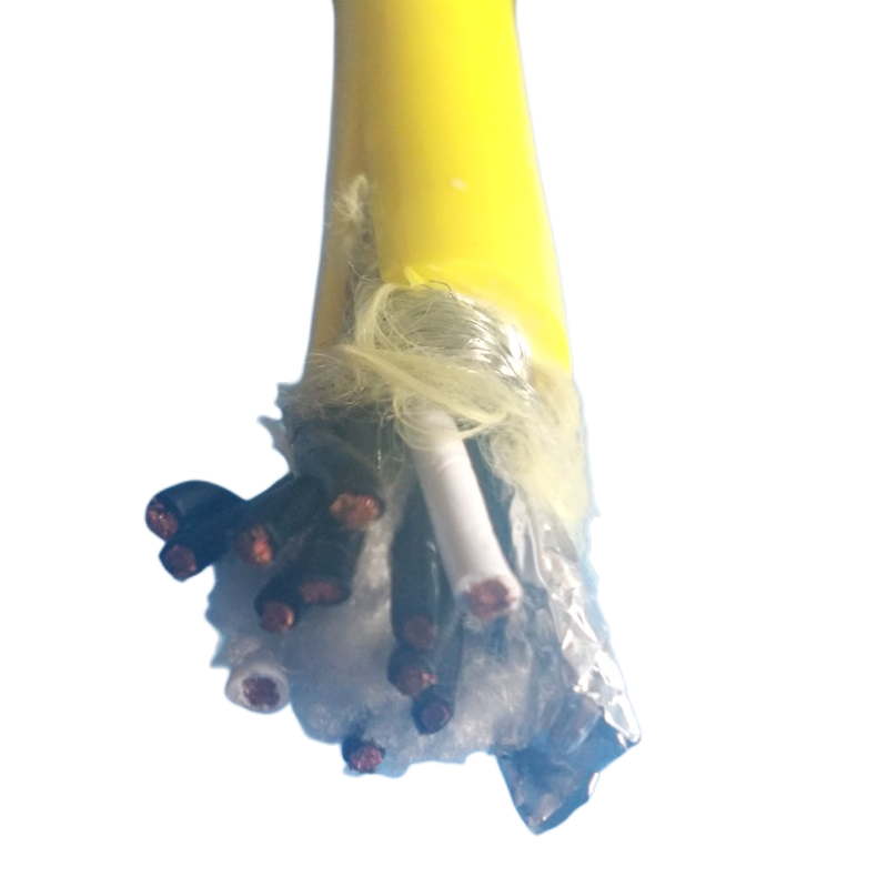
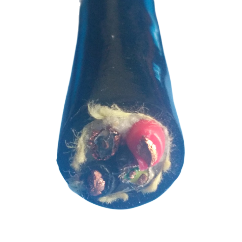
Construction — Layer by Layer
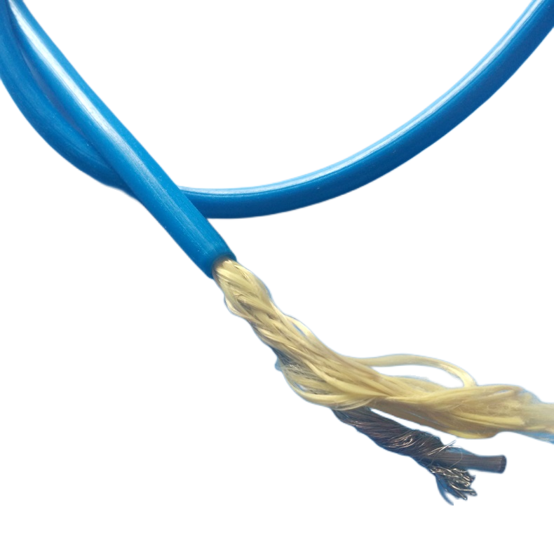
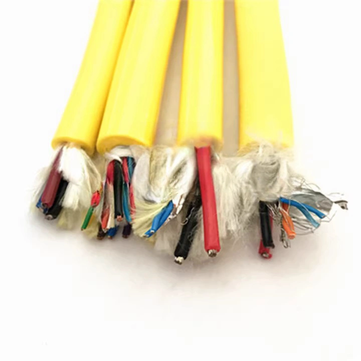
Ethernet twisted pairs
The Ethernet element in RST-EPC cables uses individually foil-screened twisted pairs. The twist rate is calibrated to meet the characteristic impedance requirement (100 Ω ± 5 Ω) and the NEXT performance floor for the rated category. Each pair’s foil screen is bonded to a drain wire that runs the full cable length — critical for PROFINET and EtherCAT, where the shield continuity requirement is specified in the protocol standard.
For Cat 6A (RST-EPC-C6A), the pairs are separated by a plastic cross-member (spline) inside the pair bundle to reduce alien crosstalk (ANEXT) — the primary limiting factor for 10GBASE-T performance in composite cables where the pair geometry is constrained by the power core cross-section.
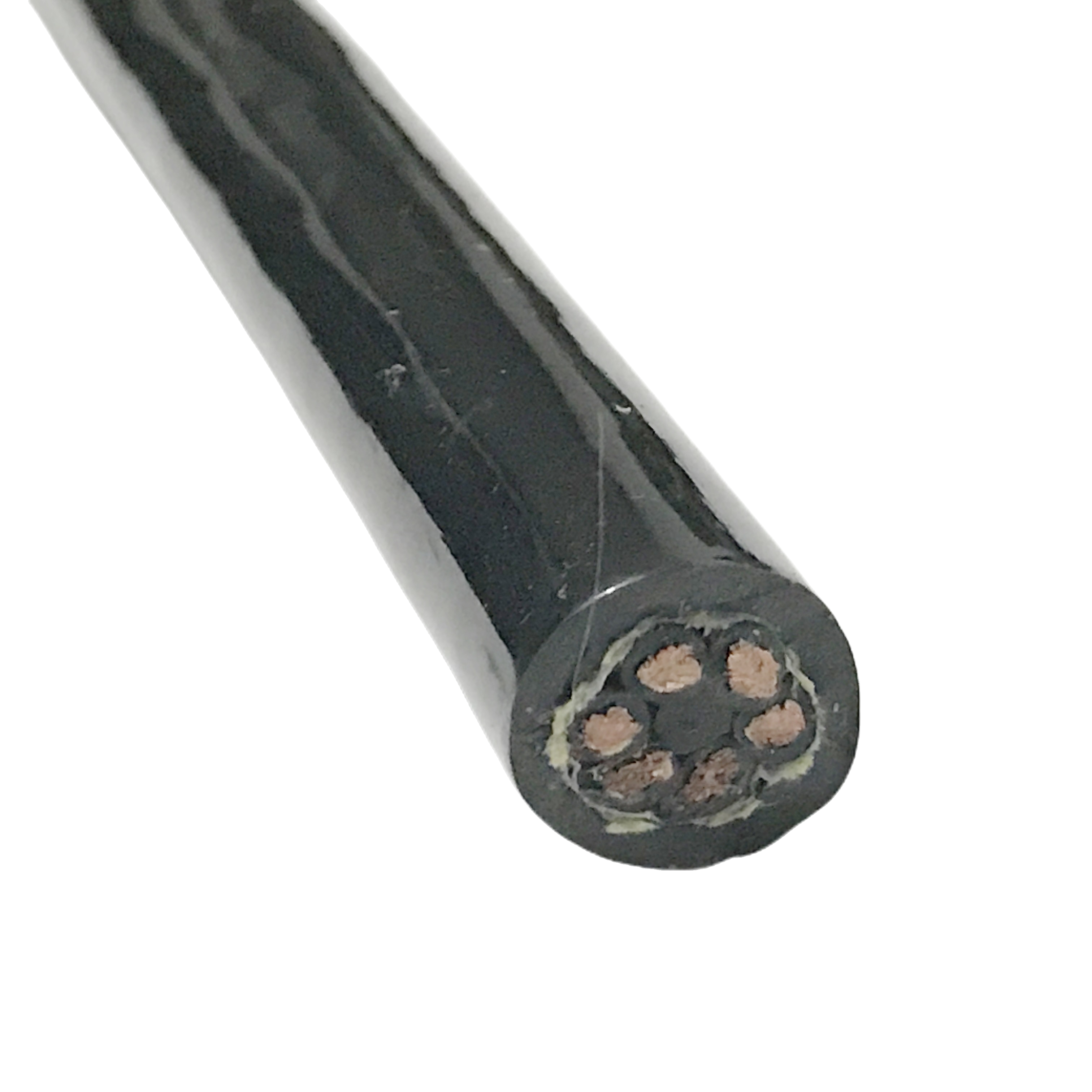
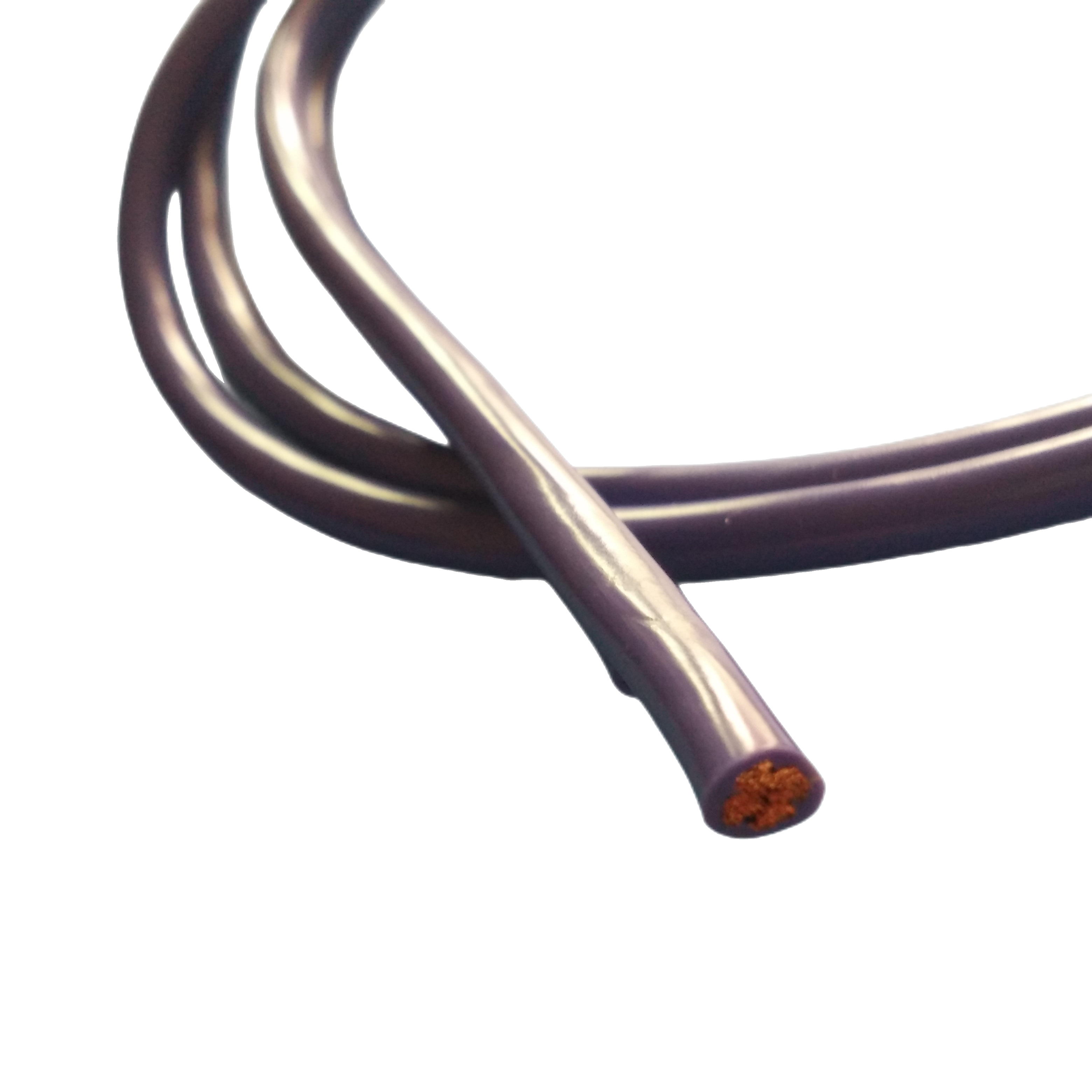
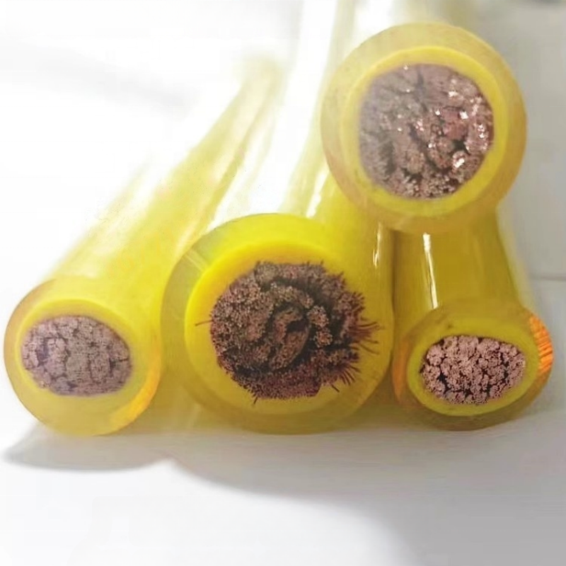
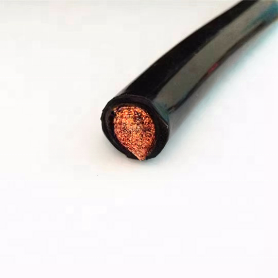
Power conductors
Power cores use oxygen-free copper (OFC), IEC 60228 Class 5 or Class 6. XLPE insulation is standard across the RST-EPC range: XLPE has a lower dielectric loss tangent than PVC, which reduces the capacitive coupling from power cores to the Ethernet pairs by approximately 35% at 100 MHz. This is not a marginal improvement — in a long hybrid cable run with a high-power load, PVC insulation on the power cores can cause enough capacitive coupling to corrupt PROFINET frames.
Power core cross-sections range from 1.5 mm² to 4.0 mm² per core in standard models. Larger cross-sections are available in OEM configurations. Current ratings follow IEC 60364-5-52 with a composite derating factor of 0.75 applied for cables installed in enclosed cable carriers.
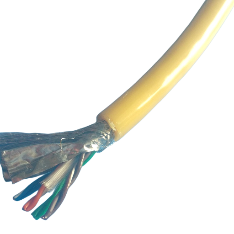
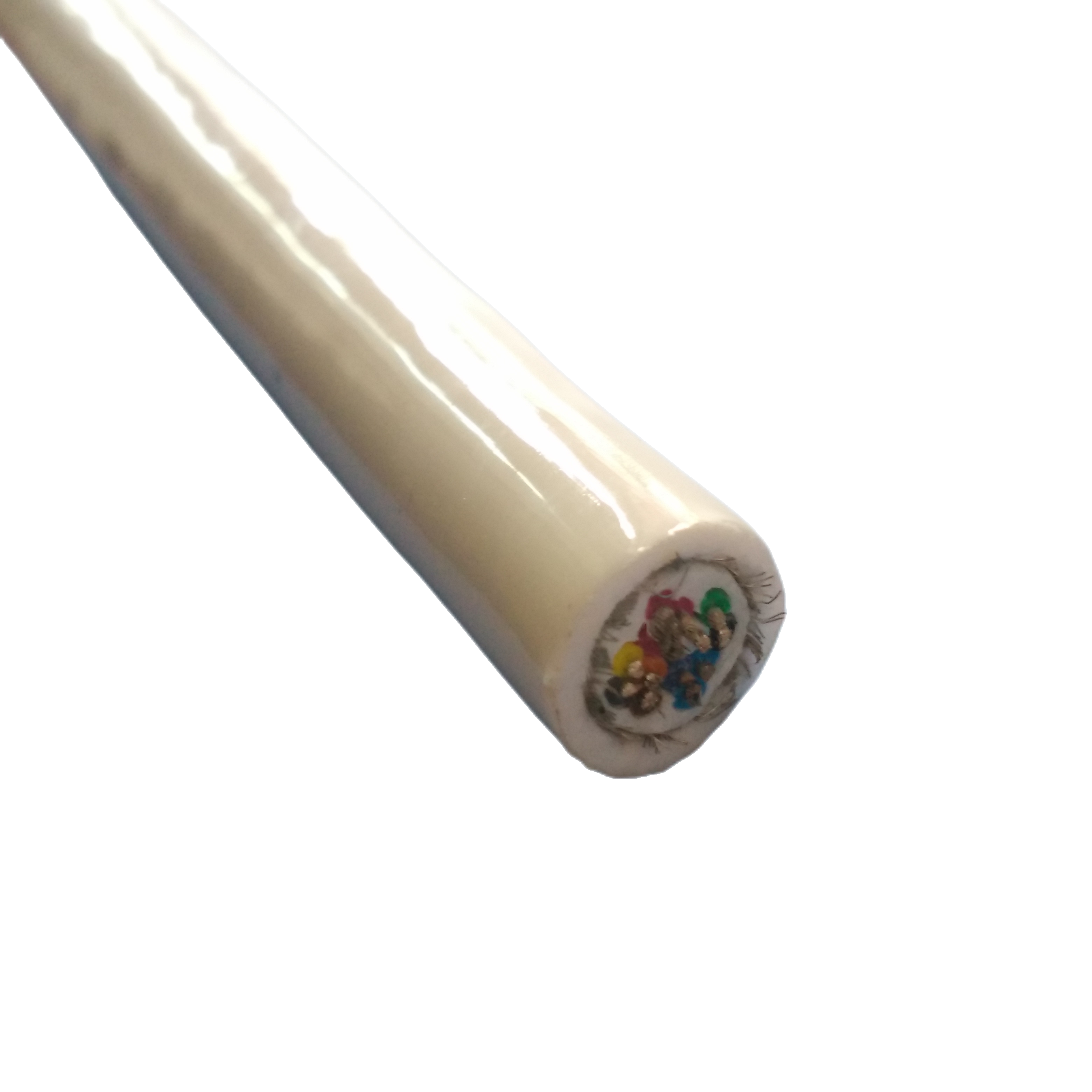
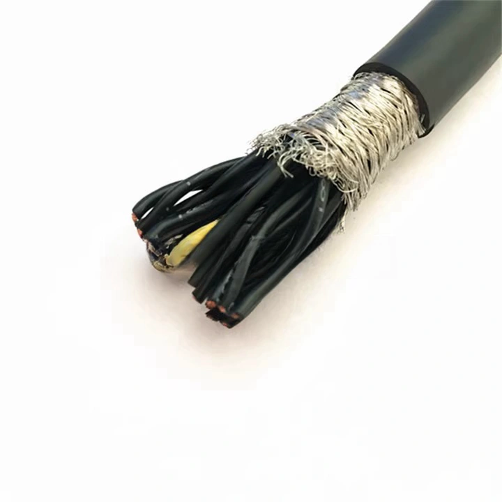
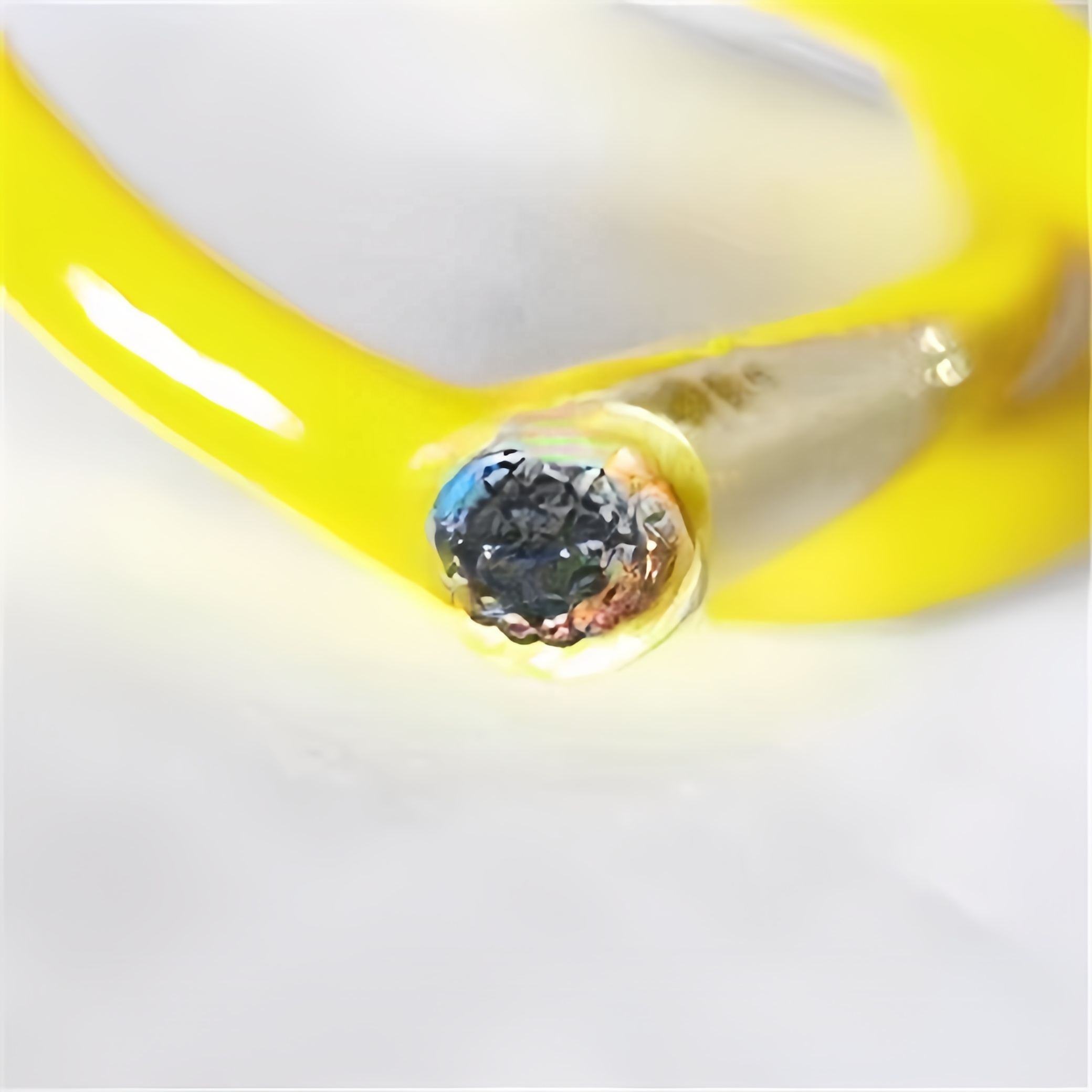
EMI barrier and outer jacket
An overall tinned copper braid shield (≥85% optical coverage) sits over the complete bundle — outside both the Ethernet pair screens and the power insulation. This overall shield provides a reference ground plane for the Ethernet pair screens and attenuates external EMI from servo drive switching harmonics, which can reach 150 kHz–0.5 MHz and couple into unshielded Cat 5e pairs at distances as short as 0.3 m.
The outer jacket is polyether TPU (standard industrial models) or UV-stabilised marine-grade PUR (marine models). Both grades are oil-resistant, rated to −40°C, and manufactured in black as standard. White RAL 9010 and grey RAL 7035 are available for food and cleanroom applications.
EMI Isolation — How Power and Data Coexist in One Cable
The coupling problem
Running power conductors alongside Ethernet pairs in the same jacket creates three EMI coupling mechanisms: capacitive coupling (electric field from voltage on power cores), inductive coupling (magnetic field from current in power cores), and common-impedance coupling (shared ground path). Each mechanism degrades Ethernet signal quality differently.
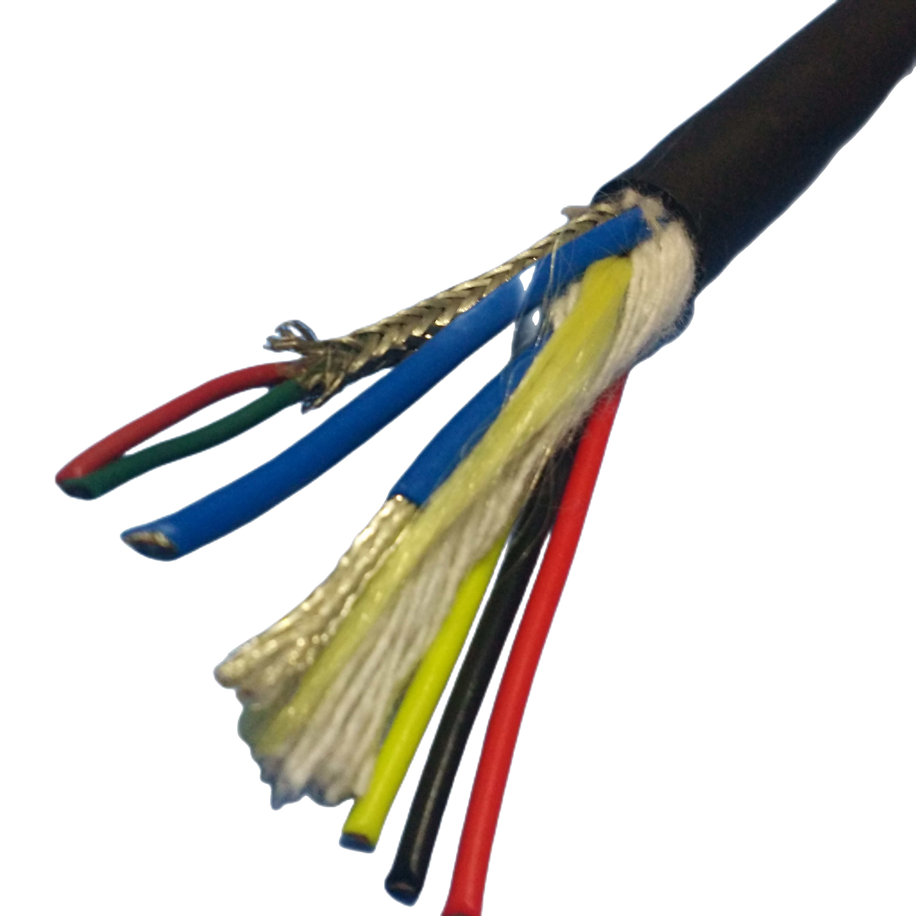
Three-tier shielding architecture
RST-EPC cables use a three-tier approach that addresses all three coupling mechanisms simultaneously. Tier 1: XLPE insulation on power cores reduces capacitive coupling by minimising the dielectric constant between power and data conductors. Tier 2: individual foil screens on each Ethernet pair block pair-specific coupling and provide a low-impedance shield return path. Tier 3: overall tinned copper braid provides a common reference plane that prevents common-impedance coupling when the cable shield is correctly bonded at both ends.
Measured EMI performance
|
Power-to-data coupling attenuation: ≥58 dB at 100 MHz with 400 VAC 50 Hz load on power cores (measured per IEC 61000-4-6 test method, in-composite configuration). This exceeds the PROFINET specification minimum of 40 dB and the EtherCAT specification minimum of 45 dB. Frame error rate validation: RST-EPC-C5-4P tested at 100 Mbit/s PROFINET IRT with 32 A load on 4 × 1.5 mm² power cores, 50 m cable length. Frame error rate: 0 errors in 10¹ frames. Test conditions per IEC 61918 validation annex. Single-end vs. both-end shield bonding: For RST-EPC cables carrying both 50 Hz/60 Hz power and Ethernet, both-end shield bonding is recommended. Single-end bonding is used only when the installation creates a ground loop risk — contact our engineering team if your grounding topology is non-standard. |
Installation Compliance Reference
Running power and data in the same cable is subject to electrical installation codes that vary by region and application. The table below summarises the compliance requirements most commonly encountered by RST-EPC customers.
|
Installation Context |
Applicable Code |
RST-EPC Compliance |
Notes |
|
Industrial factory (EU) |
IEC 60364-5-52; IEC 62443 (cybersecurity for PROFINET) |
XLPE insulation on power cores meets Annex B thermal requirements; shielding meets IEC 62443 cable integrity guidance |
No derating below the composite 0.75 factor if cable is in open air tray; additional derating in enclosed conduit |
|
Industrial factory (North America) |
NEC Article 800 (data); NEC 725 (Class 2 power); UL 508A |
UL-listed variant available (RST-EPC-UL suffix); Class 2 power cores pre-qualified for 24 VDC circuits |
NEC 800.133 requires physical separation of communications and power — hybrid cable satisfies this by design |
|
Marine (commercial vessel) |
IEC 60092-376 (data); IEC 60092-353 (power) |
RST-EPC-MAR models comply with IEC 60092-376 Type A shielded data cable requirements |
Classification society type approval (DNV, BV) available on request for marine models |
|
Offshore oil & gas |
IEC 60079 (ATEX Zone 1/2 if applicable); API RP 14F |
Standard RST-EPC is non-ATEX. ATEX-certified hybrid cable available as RST-EPC-ATEX (Zone 2, IIB T4 Gb) |
ATEX variant requires specific screen bonding to intrinsic safety barriers |
|
Food & beverage |
EHEDG; EU 1935/2004 (food contact materials for jacket) |
White TPU jacket (RAL 9010) with food-grade compound; hose material FDA 21 CFR 177.2600 compliant |
Visual inspection at daily hygiene check; white jacket enables contamination detection |
|
Offshore wind (EU) |
EN 50575 (CPR) flame classification; IEC 60092-376 |
RST-EPC-MAR-C6 available in CPR Eca classification; Cca on request |
CPR classification required for cables installed in buildings; not mandatory for offshore structures but often specified |
Technical Parameters
Ethernet pairs — performance by category
|
Parameter |
Cat 5e |
Cat 6 |
Cat 6A |
Standard |
|
Frequency range |
1–100 MHz |
1–250 MHz |
1–500 MHz |
IEC 61156-5/6/8 |
|
Characteristic impedance |
100 Ω ±15 Ω |
100 Ω ±15 Ω |
100 Ω ±15 Ω |
IEC 61156-5 |
|
NEXT @ 100 MHz |
≤−35.3 dB |
≤−44.3 dB |
≤−44.3 dB |
IEC 61156-5 |
|
Attenuation @ 100 MHz |
≤22.0 dB/100 m |
≤20.9 dB/100 m |
≤20.9 dB/100 m |
IEC 61156-5 |
|
Propagation delay |
≤5.7 ns/m |
≤5.7 ns/m |
≤5.7 ns/m |
IEC 61156-5 |
|
Max segment length (1000BASE-T) |
100 m |
100 m |
100 m |
IEEE 802.3 |
|
Max segment length (10GBASE-T) |
N/A |
55 m (typical) |
100 m |
IEEE 802.3an |
|
Power-to-pair coupling attenuation |
≥58 dB @ 100 MHz (in composite) |
≥58 dB |
N/A (tested to 500 MHz) |
IEC 61000-4-6 adapted |
Power cores
|
Parameter |
Value |
Reference |
|
Conductor material |
OFC, IEC 60228 Class 5 or 6 |
IEC 60228:2004 |
|
Cross-section range |
1.5 mm² – 4.0 mm² standard; to 10 mm² OEM |
Per model |
|
Rated voltage |
300/500 V (standard); 0.6/1 kV (3PH and MAR-C6 models) |
IEC 60502-1 |
|
HiPot test |
2,000 V AC / 5 min (300/500 V); 3,500 V AC / 5 min (0.6/1 kV) |
IEC 60502-1 Cl.17 |
|
Insulation resistance |
≥200 MΩ·km |
IEC 60502-1 Cl.18 |
|
Insulation material |
XLPE, +90°C conductor temp rated |
IEC 60502-1 |
|
Max operating current (composite, cable carrier) |
Per IEC 60364-5-52, factor 0.75 applied |
IEC 60364-5-52 |
|
Colour coding |
DIN VDE 0293-308 |
DIN VDE 0293 |
Mechanical and environmental
|
Parameter |
Standard Model (TPU) |
Marine Model (PUR) |
Standard |
|
Jacket material |
Polyether TPU, Shore A 85±3 |
Marine polyether PUR, Shore A 83±3 |
ISO 868 |
|
Jacket tensile strength |
≥48 MPa |
≥48 MPa |
ISO 37 |
|
Jacket abrasion |
≥300 cycles Taber CS-17 |
≥350 cycles Taber CS-17 |
ISO 9352 |
|
Seawater hydrolysis |
Not tested |
<1% change, 5,000 h at 23°C |
ISO 175 |
|
Operating temp. (dynamic) |
−40°C to +105°C |
−40°C to +80°C surface |
IEC 60811-501 |
|
Min bend radius (static) |
5× OD |
5× OD |
— |
|
Min bend radius (FLX model) |
7.5× OD (drag chain rated) |
— |
IEC 60794-1-2 E10 adapted |
|
Oil resistance |
Excellent |
Excellent |
IEC 60811-406 |
|
UV resistance |
Moderate (standard TPU) |
1,000 h xenon arc, ≤80% tensile |
IEC 60811-401 |
|
Overall shield |
Tinned Cu braid ≥85% optical coverage |
Same |
IEC 61156-5 |
Project References
Customer names withheld at client request. Technical data verified; available under NDA for qualified organisations.
|
Project |
System |
RST-EPC Model |
Challenge |
Result & Duration |
|
Automotive assembly plant, Germany |
192 PROFINET I/O nodes, 24 VDC supply + 100 Mbit/s, 18 m cable carrier per node |
RST-EPC-C5-4P, drag chain rated, 3,500 m total |
Separate data and power cables consumed 71% of cable carrier fill. Thermal damage to data cable at mid-chain bend radius every 14 months. RST-EPC-C5-4P FLX variant reduced fill ratio to 44%; no thermal events. |
2022–2024, 2 years. Zero cable replacements outside planned PM. |
|
Offshore wind farm, North Sea |
14 turbine nacelle controllers, Modbus TCP + 230 VAC supply, 60 m run per turbine from J-box to nacelle MCC |
RST-EPC-MAR-C6, 0.6/1 kV rated, 840 m total |
J-box had one gland entry per turbine. Existing configuration used separate data and power cables through a shared gland — gland compression was insufficient to maintain IP67. Single RST-EPC-MAR-C6 through a 20 mm gland achieved IP68 at 1 m. |
Installed 2023. Annual inspection: zero IP rating failures across 14 turbines. |
|
Container terminal, Singapore |
Ship-to-shore crane SCADA nodes, EtherCAT + 400 VAC 3-phase crane supply section |
RST-EPC-3PH-C5, 3×4.0 mm² + Cat 5e pairs, 12 cables at 85 m each |
Previous installation used separate EtherCAT fibre cable and 3-phase power cable through the crane cable carrier. Carrier fill at 68%. RST-EPC-3PH-C5 reduced fill to 41% and eliminated one cable gland per crane. |
2023. Zero EtherCAT frame errors reported since installation. |
|
Food packaging line, Netherlands |
24 servo I/O nodes, EtherCAT + 24 VDC, daily disinfectant washdown, IP69K enclosures |
RST-EPC-C5-4P, white RAL 9010 jacket, food-grade compound |
Daily sodium hypochlorite (2%) washdown was degrading standard TPU jacket surface within 8 months. Food-grade compound RST-EPC-C5-4P showed no surface degradation after 12-month exposure test. |
2023–ongoing. Passed EHEDG visual inspection 14 consecutive monthly audits. |
|
Research vessel, Norwegian coast |
6 deck instrument nodes: Ethernet + 24 VDC, exposed deck, saltwater spray, −20°C winter operation |
RST-EPC-MAR-C5, UV-stabilised marine PUR, 90 m total |
Deck cable needed to withstand saltwater spray, UV, and sub-zero winter temperatures while maintaining 100 Mbit/s network integrity. Marine PUR jacket maintained flexibility at −18°C deck temperature; network uptime 99.7% over 12-month research cruise. |
2023. Ongoing use across 2 research vessel deployments. |
FAQ — Automation Engineers & Marine System Integrators
Q1: Does running power alongside Ethernet corrupt the network signal?
With correct shielding architecture, no. The RST-EPC three-tier shield (XLPE insulation + individual pair foil screens + overall braid) achieves ≥58 dB power-to-data coupling attenuation at 100 MHz. This is validated in PROFINET IRT testing at 100 Mbit/s with a 32 A load on the power cores: zero frame errors in 10⁹ frames. The critical requirement is correct shield bonding — the overall braid must be bonded to a low-impedance earth at both ends for maximum EMI rejection.
Q2: What is the maximum power cable length before voltage drop becomes a problem?
Voltage drop depends on conductor cross-section, current, and cable length. For a 24 VDC system with a 5% VD target: a 1.5 mm² core at 10 A is limited to approximately 18 m; upgrading to 2.5 mm² extends this to 30 m. For runs beyond 50 m at currents above 10 A, specify 4.0 mm² cores. Rousheng provides a voltage-drop calculation with every technical enquiry — specify operating current and maximum acceptable VD percentage.
Q3: Can I use RST-EPC for Power over Ethernet (PoE++) at the same time as a separate power circuit?
Not recommended in the same cable. PoE++ uses the data pairs as the power conductor. Adding a separate 230 VAC power circuit in the same cable jacket creates a mixed-voltage environment where the PoE power path (data pairs) is in proximity to mains power conductors. This does not comply with IEEE 802.3bt PoE++ isolation requirements. Use a standard PoE cable for PoE-only applications or specify RST-EPC without the PoE feature — the power cores replace the PoE function at higher power levels.
Q4: Is a Cat 5e pair in a composite cable the same as a standalone Cat 5e cable?
The pair itself meets the same electrical specification (IEC 61156-5). However, composite cable pairs experience additional crosstalk from adjacent power cores that is not present in standalone Cat 5e cables. RST-EPC manages this through individual pair foil screens. The power-to-data coupling attenuation of ≥58 dB at 100 MHz ensures that the effective NEXT and insertion loss performance of the composite pair remains within Cat 5e specification. We test every RST-EPC cable in the complete composite configuration, not as isolated pairs.
Q5: Does the hybrid cable require a special cable gland?
Standard M20 or M25 cable glands cover the OD range of most RST-EPC models (10.8–19.0 mm). For marine and IP67/IP68 applications, use a gland rated to the enclosure IP requirement. Inside the gland, the power and Ethernet conductors are separated and routed to their respective terminal blocks or connectors. The single gland entry must be rated for the highest voltage in the cable — if 0.6/1 kV power cores are present, use a 1 kV rated gland. Rousheng provides gland selection guidance with marine model orders.
Q6: Can RST-EPC-FLX be used in a robotic arm application with continuous torsion?
RST-EPC-FLX is validated for drag chain duty (planar flex, 7.5× OD dynamic bend radius, ≥5 million cycles). For robotic arm applications with simultaneous torsion (±180°/m), specify the torsion-rated variant (RST-EPC-FLX-T suffix). The torsion variant uses a different cabling geometry and a longer lay length that accommodates rotational stress without imparting twist to the Ethernet pairs — pair twist rate stability is critical for maintaining 100 Ω characteristic impedance under mechanical loading.
Manufacturer Background — Shanghai Rousheng
|
Production & testing Dedicated composite extrusion line: power and data elements cabled simultaneously 100% HiPot test: all power cores and signal pairs per drum Ethernet pair test: insertion loss + NEXT + impedance per drum (Fluke DTX-1800) EMI coupling attenuation measured on sample per production batch Conductor resistance certificate per drum (IEC 60228) Batch-level traceability: copper lot + insulation compound + jacket compound |
Certifications ISO 9001:2015 quality management system CE marking — LVD Directive 2014/35/EU RoHS 2 / REACH SVHC compliance DNV / Bureau Veritas type approval on request (marine models) UL listing on request (RST-EPC-UL suffix, North America) ATEX Zone 2 IIB T4 Gb on request (RST-EPC-ATEX) CNAS-accredited third-party lab reports on request |
Every RST-EPC technical enquiry receives a voltage-drop calculation, cable carrier fill-ratio estimate, and EMI coupling assessment based on the specific protocol and power load specified. These are provided at no charge as part of the pre-sale engineering review process.
Request a Quote, Sample, or EMI Assessment
|
Contact Email: Jerry@rstlkable.com Phone: +86-021-50759965 Mobile: +86-13482197396 Address: No. 2591 Fengzhe Road, Fengxian District, Shanghai Quote within 24 hours. HiPot certificate + Ethernet pair test report included with every drum. |
Include in your enquiry 1. Industrial Ethernet protocol (EtherCAT, PROFINET, Modbus TCP, etc.) 2. Power: voltage (VAC/VDC), current (A), phases (1 or 3) 3. Cable run length and installation method (carrier, conduit, open tray) 4. Environment: industrial, marine, food, ATEX 5. Flex requirement: static, drag chain, robotic arm torsion 6. Compliance requirement: CE, UL, DNV, ATEX, EHEDG We include a VD calculation, fill-ratio estimate, and EMI coupling assessment with every technical reply. |