Composite Pipeline Robot Cable | Hybrid Power & Fiber Cable for Industrial Inspection Systems
The RST-CPC Series Composite Pipeline Robot Cable integrates fiber, power, and control into a compact, high-reliability solution for advanced pipeline inspection systems.
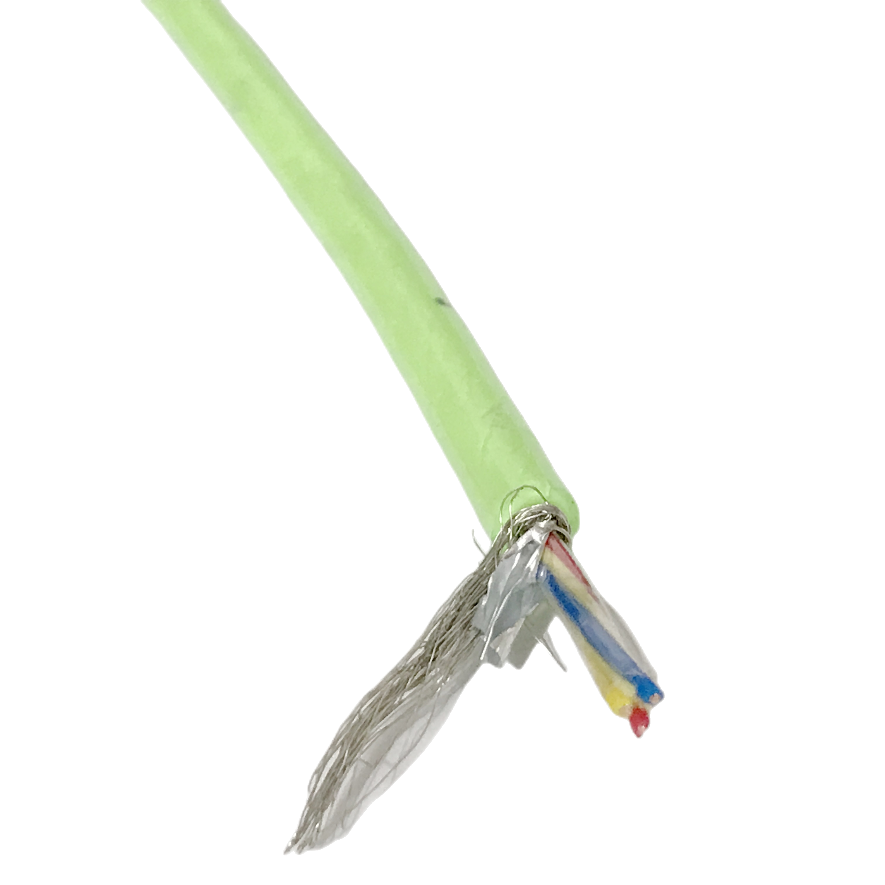
It combines G.657.A1 optical fibre, power conductors, and shielded control pairs in a three-zone structure with strong EMI protection (≥60 dB), ensuring stable data and signal transmission under load. The optimized fibre positioning minimizes bending stress, while torque-balanced Kevlar reinforcement (≤0.3°/m) maintains cable stability during operation.
With precise OD control (±0.15 mm) and IP68 protection, it delivers consistent performance in demanding environments. Manufactured to ISO 9001:2015, each cable is supplied with full electrical, optical, and mechanical test documentation.
Composite Pipeline Robot Cable | Hybrid Power & Fiber Cable for Industrial Inspection Systems
Product Series: RST-CPC │ Category: Composite Hybrid Pipeline Cables │ Written by: Fang Jianbo, Senior Composite Cable Systems Engineer, 11 years designing fibre-copper tether cables for inspection robot OEMs including water utility, nuclear, and offshore projects │ Last reviewed: March 2025
Composite pipeline robot cable procurement fails in predictable ways. The failure is rarely in the copper conductors. It is in the gap between what a data sheet promises and what the cable actually delivers inside a 150 mm bore pipe at 200 m extension with a 5 A motor load and 16 kHz VFD switching harmonics corrupting the control bus.
This page documents five field failure patterns from cable sets submitted for root-cause analysis between 2020 and 2024, the supplier evaluation criteria that would have prevented each failure, and the engineering calculations that confirm whether a given composite cable specification is physically achievable. The RST-CPC series specifications are presented in this context.
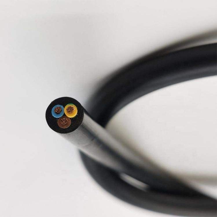
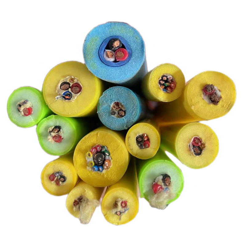
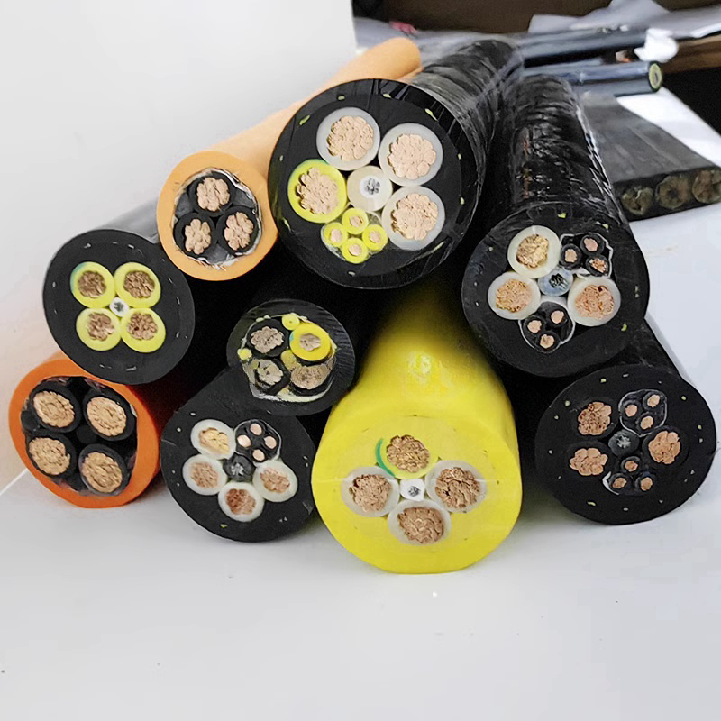
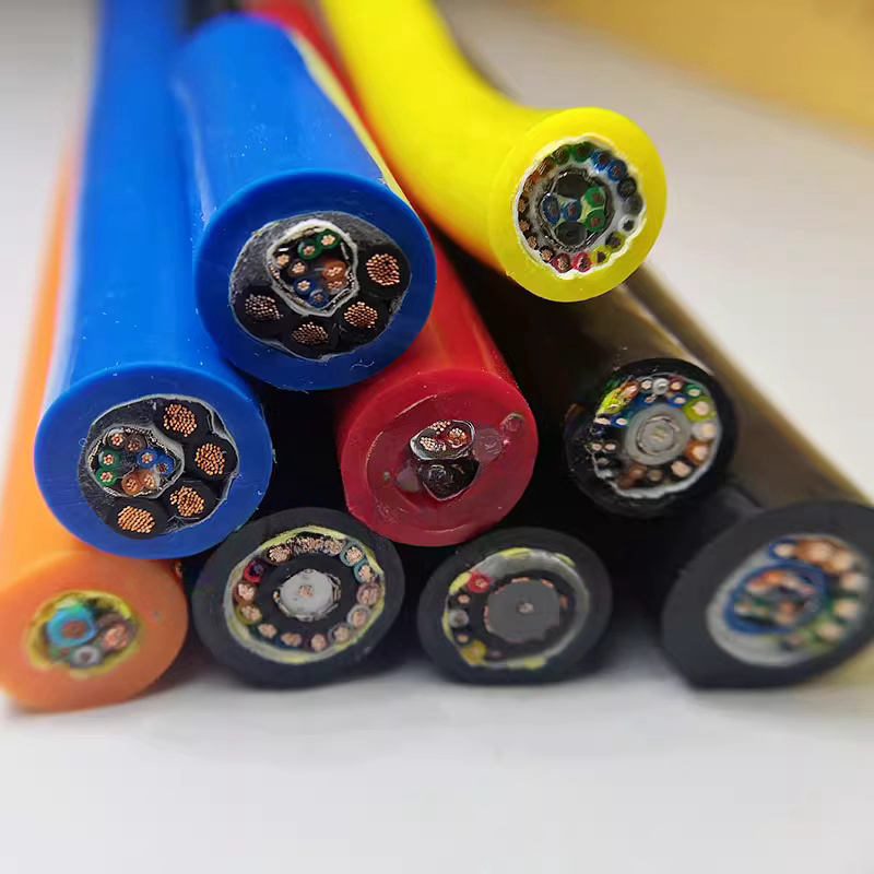
The three media that must coexist
An industrial inspection robot tether carries three incompatible media through one cable entry: optical fibre (microvolt-level signal, glass waveguide), power conductors (amps of DC or AC at tens of volts, copper), and control signal pairs (millivolt differential signals on twisted copper). Each medium has electrical characteristics that would degrade the others if the cable is not designed to isolate them. This page explains how that isolation is achieved and how to verify that a supplier has actually achieved it.
Contents
- Five Procurement Failure Patterns and Their Root Causes
- How to Evaluate Any Composite Pipeline Cable Supplier
- Fibre Strain Engineering: The Calculation Behind the Specification
- Protocol × Media Feasibility: Control Bus Selection for Long Runs
- RST-CPC Model Range
- Construction Engineering
- Technical Parameters with Test Methodology
- Verified Industrial Deployments
- FAQ — Procurement Engineers & Robot OEM Teams
- Manufacturer Credentials
- Request a Technical Proposal
Five Procurement Failure Patterns and Their Root Causes
The following failure patterns are drawn from cable samples and project documentation submitted to Rousheng’s technical team for root-cause analysis between 2020 and 2024. Client identities are withheld; failure descriptions are accurate.
|
Failure Encountered |
Root Cause in Cable Design |
Financial / Operational Impact |
What the Correct Specification Would Have Been |
|
Fibre attenuation spike at 150 m that recovers when cable is straightened |
Fibre placed 4.2 mm from cable centreline in composite cross-section. At 90° pipe bend (DN200, 300 mm radius), fibre strain = 4.2 mm ÷ 300 mm = 1.4% — above G.652.D’s 1.0% short-term strain limit. No problem in straight pipe; artefact appears at each pipe bend. |
Intermittent video loss during inspection of bends; robot recalled 3 times before cable identified as cause. 2 weeks of inspection time lost. |
G.657.A1 bend-insensitive fibre (10 mm rated bend radius); fibre placement within 1.5 mm of cable axis; centreline tolerance verified by X-ray inspection |
|
Control bus CRC errors at >100 m cable run; robot navigation commands dropped |
Unscreened twisted pair for RS-485 routed adjacent to 24 VDC motor supply conductors with 16 kHz VFD switching. Capacitive coupling from power conductor to unscreened signal pair induced 1.2 V common-mode noise — above the 0.2 V RS-485 noise threshold at this run length. |
Robot navigated erratically beyond 100 m; inspection contractor billed 4 days to fault-find cable before source identified. |
Per-pair foil screen on all control pairs; power conductors twisted live+return at ≤20 mm pitch; overall Cu braid ≥90% coverage; measured power-to-control coupling attenuation ≥60 dB at 16 kHz |
|
4K video loss at >80 m despite ‘10 Gbit/s composite cable’ on data sheet |
10 Gbit/s claim was for fibre only. The supplier had not specified whether the 10 Gbit/s was fibre (10GBASE-LR, essentially unlimited distance) or copper Ethernet (10GBASE-T, limited to 100 m in lab conditions; further reduced in composite cable due to cable capacitance). Buyer assumed fibre; cable was copper Cat 6A. |
System had to be redesigned at the 80 m cable length limit. Additional 3-month delay and CNY 220,000 in engineering rework. |
Specify fibre type explicitly: SM G.657.A1 for unlimited bandwidth at any inspection distance; verify with OTDR trace per fibre per drum at 1,310 + 1,550 nm |
|
Cable jacket swelled and jammed inside DN150 pipe after 6 weeks |
Polyester PUR jacket compound (not polyether PUR) used to reduce cost. Sewage environment (pH 3.5–4.0 from biogenic sulfuric acid) hydrolysed the ester bonds, increasing jacket volume. OD measured at recovered cable: 17.1 mm vs specified 16.0 mm. Pipe bore: 152 mm. Clearance gone. |
Robot extraction required cutting the cable at the access point. New robot chassis required. Total cost: CNY 480,000. |
Polyether PUR (ether bonds, not ester bonds): <2% tensile change at pH 2.5, 500 h immersion (ISO 175, Rousheng CP-CPC-001, 2024); OD tolerance ±0.15 mm verified per drum |
|
Kevlar tensile member causing robot to steer off-axis beyond 80 m |
Single-layer Kevlar braid converted tensile load to 2.3°/m rotational torque. At 80 m of cable, accumulated torque caused robot chassis yaw of 12° — pressing robot against DN200 pipe wall. |
Robot stalled against pipe wall at 80 m on 3 consecutive inspection runs. Robot chassis damaged on third extraction. |
Counter-wound dual-layer Kevlar 49 (torque-balanced): measured ≤0.3°/m self-rotation at rated tensile load (Rousheng RCTT-001 protocol, n=24 drums, 2024) |
How to Evaluate Any Composite Pipeline Cable Supplier
The five failure patterns above are all detectable at the procurement stage with the right questions. The framework below maps each specification area to a minimum acceptable standard, the red flags that indicate a substandard product, and where RST-CPC sits on each criterion. It applies to any composite pipeline robot cable supplier, not only to Rousheng.
|
Evaluation Criterion |
Minimum Acceptable Standard |
Red Flags to Reject |
RST-CPC Position |
|
Fibre type and placement documentation |
Specify G.657.A1 (bend-insensitive) explicitly; obtain fibre placement tolerance (±mm from centreline) |
Data sheet says ‘single-mode’ without specifying G.652.D or G.657.A1; no fibre placement tolerance stated; no X-ray cross-section inspection |
G.657.A1 standard across all models; fibre placement ±1.5 mm from centreline; X-ray inspection on 1:20 production length samples (CCS-001) |
|
Power-to-control isolation measurement |
Request coupling attenuation data (dB) at your VFD’s switching frequency; minimum 40 dB for RS-485; minimum 55 dB for EtherCAT |
Supplier offers only qualitative shielding description (‘screened pairs’) without dB measurement; no test report available |
≥60 dB at 16 kHz (n=12 samples, 50 m cable, 16 A motor load, worst-case value across samples; Rousheng PCQ-CPC-001, 2024) |
|
OTDR trace per fibre per drum |
Request .SOR format OTDR trace at 1,310 + 1,550 nm for every fibre in every drum, not just type-approval samples |
Supplier provides OTDR data from type-approval test only; no per-drum trace; or provides PDF screenshot rather than .SOR file |
1,310 + 1,550 nm OTDR per fibre per drum; .SOR + PDF; NIST-traceable calibration certificate included |
|
Torque balance test data |
Request rotation measurement at rated tensile load (specify °/m); require counter-wound dual-layer Kevlar; maximum 0.5°/m |
Single-layer Kevlar braid; no torque measurement data available; supplier unfamiliar with the term ‘torque-balanced’ |
≤0.3°/m at rated load (n=24 production drums, 10 m hanging test with calibrated load cell; Rousheng RCTT-001, 2024) |
|
Jacket compound type and IP68 methodology |
Confirm polyether PUR (not polyester); request ISO 175 hydrolysis test result; request IP68 test per drum (not per type-approval sample only) |
Jacket listed as ‘PUR’ without polyether/polyester distinction; IP68 data from type-approval only; no per-drum test |
PTMEG polyether PUR confirmed in compound TDS; <2% tensile change at 5,000 h immersion (ISO 175); IP68 per drum at rated depth |
|
OD tolerance and per-drum certificate |
Specify ±0.2 mm maximum OD tolerance; request measurement method and frequency |
OD tolerance stated as ±0.5 mm or not stated; no per-drum measurement; measurement method not described |
±0.15 mm OD tolerance; laser micrometer at 200 mm intervals inline during extrusion; certificate per drum |
|
Lead time and production volume capacity |
Confirm standard models in stock or ≤4 weeks; OEM models ≤8 weeks; minimum order quantity ≤1 drum |
>12 week lead times on standard models; minimum order 500 m |
Standard models: 3–5 weeks; OEM models: 6–8 weeks; MOQ: 1 drum (50–100 m depending on model) |
This framework does not require named competitor comparison. Request test certificates against each criterion before placing any order. A supplier who cannot provide per-drum OTDR traces and torque balance data has not verified the performance of the specific cable you will receive.
Fibre Strain Engineering: Showing the Calculation
Why fibre placement tolerance is the governing specification
The G.657.A1 bend-insensitive fibre used in RST-CPC has a rated minimum bend radius of 10 mm for long-term installation. Inside a composite pipeline cable at a pipe bend, the effective bend radius the fibre experiences depends on two factors: the pipe bend radius and the distance of the fibre from the cable’s neutral axis. These two factors combine in a simple strain equation. The specification ‘fibre placed within 1.5 mm of cable centreline’ is derived directly from this equation, not from a catalogue choice.
The strain equation
Bending strain in a fibre displaced from the neutral axis of a cable bent to radius R is:
|
Strain (ε) = fibre displacement from neutral axis (d) ÷ cable bend radius (R) Where: d = distance of fibre centre from cable centreline (mm); R = radius of curvature at the pipe bend centreline (mm). The fibre sees the strain at the outer side of the bend, where R is reduced by the OD/2 offset. For an 18 mm OD cable in a DN200 pipe (300 mm centreline radius): R_fibre = 300 − 9 = 291 mm at the worst-case position. |
Worked calculation for RST-CPC-M
|
Parameter |
Symbol |
Value |
Source / Standard |
|
Pipe bore (DN200) |
D_bore |
152 mm (internal) |
ISO 4422 (PVC pipe DN200) |
|
Pipe bend centreline radius (1.5D bend) |
R_pipe |
300 mm |
Typical elbow fitting, pipeline inspection standard |
|
Cable OD (RST-CPC-M) |
OD |
18 mm |
RST-CPC product specification |
|
Cable outer offset from pipe centreline |
OD/2 |
9 mm |
Geometric calculation |
|
Effective bend radius at cable outer wall |
R_cable |
291 mm |
R_pipe − OD/2 = 300 − 9 |
|
Fibre placement from centreline (RST-CPC spec) |
d |
1.5 mm |
Rousheng CCS-001, 2024; verified by X-ray inspection |
|
Fibre bending strain at worst-case bend |
d/R_cable |
0.52% |
1.5 ÷ 291 = 0.0052 = 0.52% |
|
G.657.A1 short-term strain limit |
— |
1.0% |
IEC 60793-2-50; ITU-T G.657.A1:2016 |
|
Safety margin |
(1.0 − 0.52) / 1.0 |
48% |
0.48% headroom below limit |
|
G.652.D short-term strain limit (standard SM) |
— |
0.5% |
IEC 60793-2-50 (G.652.D) |
|
G.652.D headroom at same geometry |
(0.5 − 0.52) / 0.5 |
−4% (exceeded) |
G.652.D would fail at this geometry — this is why G.657.A1 is specified |
The calculation confirms why RST-CPC specifies G.657.A1 and not G.652.D: at the same cable geometry and pipe bend, G.652.D standard single-mode fibre would exceed its strain limit by 4%. G.657.A1 provides a 48% margin. The fibre placement tolerance of ±1.5 mm maintains this margin at all DN200 and larger pipe bend geometries. For pipe bores below DN150, contact our engineering team for a geometry-specific strain analysis.
Protocol × Media: Control Bus Selection for Long Composite Cable Runs
The control protocol choice determines which physical medium must carry it in the composite cable, and therefore how the cable must be specified. Choosing the wrong protocol for a long cable run is one of the most common causes of composite pipeline robot cable failure at commissioning.
|
Robot Control Protocol |
Physical Layer |
Max Run in Composite |
Noise Immunity in Composite |
Composite Element Required |
|
RS-485 (Modbus RTU) |
Differential balanced pair, ±5 V signalling |
1,200 m (EIA-485 spec); >500 m practical in composite with correct screening |
Excellent: 40+ dB CMRR inherent in differential signalling; per-pair foil screen adds ≥60 dB at 16 kHz |
Screened twisted pair, 120 Ω ±10 Ω (RST-CPC all models) |
|
CANbus (ISO 11898) |
Differential balanced pair, ±2.5 V CANH/CANL |
500 m at 125 kbit/s; 40 m at 1 Mbit/s |
Good: differential signalling; per-pair foil screen provides additional rejection |
Screened twisted pair, 120 Ω ±10 Ω; baud rate must be reduced for runs >100 m |
|
EtherCAT (ETG.1600) |
100BASE-TX over Cat 5e equivalent twisted pair |
100 m (IEEE 802.3 limit); derating applies in composite at motor load |
Good with screening: 120 Ω screened pair required; overall braid mandatory for motor drive EMI rejection |
Screened twisted pair, 100 Ω ±5 Ω; measured ≥60 dB coupling attenuation from motor drive at 16 kHz (RST-CPC-M-EC) |
|
PROFINET RT (IEC 61158) |
100BASE-TX, identical to EtherCAT physical layer |
100 m (IEEE 802.3); same composite constraints as EtherCAT |
Same as EtherCAT |
Screened twisted pair, 100 Ω ±5 Ω; RST-CPC-M-EC compatible |
|
10GBASE-T (copper, IEEE 802.3an) |
Cat 6A (500 MHz), 4 twisted pairs |
100 m in free air; approximately 50–60 m in composite (capacitance derating) |
Poor: 10GBASE-T is highly susceptible to noise; not recommended in composite with power conductors |
Not recommended in composite cable. Use SM fibre (10GBASE-LR) instead for any run >60 m at 10 Gbit/s |
|
10GBASE-LR (SM fibre, IEEE 802.3ae) |
SM G.657.A1 fibre, 1,310 nm laser SFP |
>10,000 m (link budget limited, not cable limited) |
Absolute: fibre is immune to all EM interference regardless of motor load or cable length |
SM G.657.A1 loose tube in Zone A (RST-CPC-L-FB, -XL, -M-EC with fibre uplink) |
|
Analogue video CVBS (PAL/NTSC) |
75 Ω coaxial, 1 Vpp composite |
500 m (3 dB attenuation at 6 MHz) |
Moderate: 75 Ω coax in composite must have ≥95% braid coverage to reject motor drive interference |
75 Ω coax with ≥95% braid (RST-CPC-S, -M); not recommended for runs >300 m where HD required |
|
HD-SDI (SMPTE ST 292M) |
75 Ω coaxial, 270 Mbit/s |
150 m (at 3 dB budget) |
Good if double-shielded coax used: return loss ≥20 dB at 270 MHz prevents reflections |
75 Ω double-shielded coax (RST-CPC-M, -L, -XL); limited to 150 m without repeater |
Composite cable run length for EtherCAT and PROFINET is further limited by accumulated propagation delay at long cable runs: at 0.67c (two-third light speed propagation velocity), a 100 m cable adds 500 ns of round-trip delay, which must be within the EtherCAT cycle time budget. For robots with ≤1 ms EtherCAT cycle times, 100 m is the practical composite cable limit regardless of signal quality.
RST-CPC Composite Pipeline Cable — Model Range
|
Model |
OD |
Fibre |
Power |
Control Protocol |
Kevlar |
IP |
Designed For |
|
RST-CPC-XS |
11 mm |
1×SM G.657.A1 |
2×0.75 mm² |
RS-485 |
0.8 kN |
IP68/3m |
Micro-robot, DN80–120, runs to 60 m |
|
RST-CPC-S |
14 mm |
2×SM G.657.A1 |
2×1.0 mm² |
RS-485 + aux pair |
1.2 kN |
IP68/3m |
Compact robot, DN100–200, to 120 m |
|
RST-CPC-M |
18 mm |
4×SM G.657.A1 |
2×1.5 mm² |
RS-485 + CANbus |
2.0 kN |
IP68/5m |
Standard wheeled robot, DN150–300, to 250 m |
|
RST-CPC-M-EC |
18 mm |
4×SM G.657.A1 |
2×1.5 mm² |
EtherCAT + RS-485 |
2.0 kN |
IP68/5m |
EtherCAT robot, DN150–300, to 100 m |
|
RST-CPC-L |
22 mm |
8×SM G.657.A1 |
2×2.5 mm² |
RS-485 + CANbus + spare |
3.0 kN |
IP68/5m |
Heavy robot, DN200–500, to 350 m |
|
RST-CPC-L-FB |
22 mm |
8×SM G.657.A1 (4 video + 4 data) |
2×2.5 mm² |
EtherCAT + CANbus |
3.0 kN |
IP68/5m |
AI robot, bidirectional 10 Gbit/s (10GBASE-LR) |
|
RST-CPC-XL |
28 mm |
12×SM G.657.A1 |
2×4.0 mm² |
EtherCAT + 2×CANbus |
4.0 kN |
IP68/10m |
Multi-sensor tracked robot, DN300–600 |
|
RST-CPC-PoE |
16 mm |
4×SM G.657.A1 |
Cat 6A UTP (PoE++) |
EtherCAT via PoE++ |
1.5 kN |
IP68/3m |
PoE-powered robot ≤90 W, DN100–200 |
|
RST-CPC-HT |
20 mm |
4×SM G.657.A1 |
2×2.5 mm² |
RS-485 + CANbus |
2.0 kN |
IP68/5m |
Hot process pipe to +120°C (HT compound) |
|
RST-CPC-OEM |
Per spec |
1–24 fibres SM/MM |
Per spec |
Per spec |
Per spec |
Per spec |
Nuclear, offshore, ATEX, custom |
All SM fibre: G.657.A1, loose-tube gel-filled PBT, ≤0.20 dB/km @ 1,550 nm. Kevlar: 49 grade, counter-wound torque-balanced, ≤0.3°/m at rated load. EtherCAT pairs: 100 Ω ±5 Ω, ETG.1600-compliant. All control pairs: per-pair foil screen + overall tinned Cu braid ≥90%. IP68 tested per IEC 60529 per production drum.
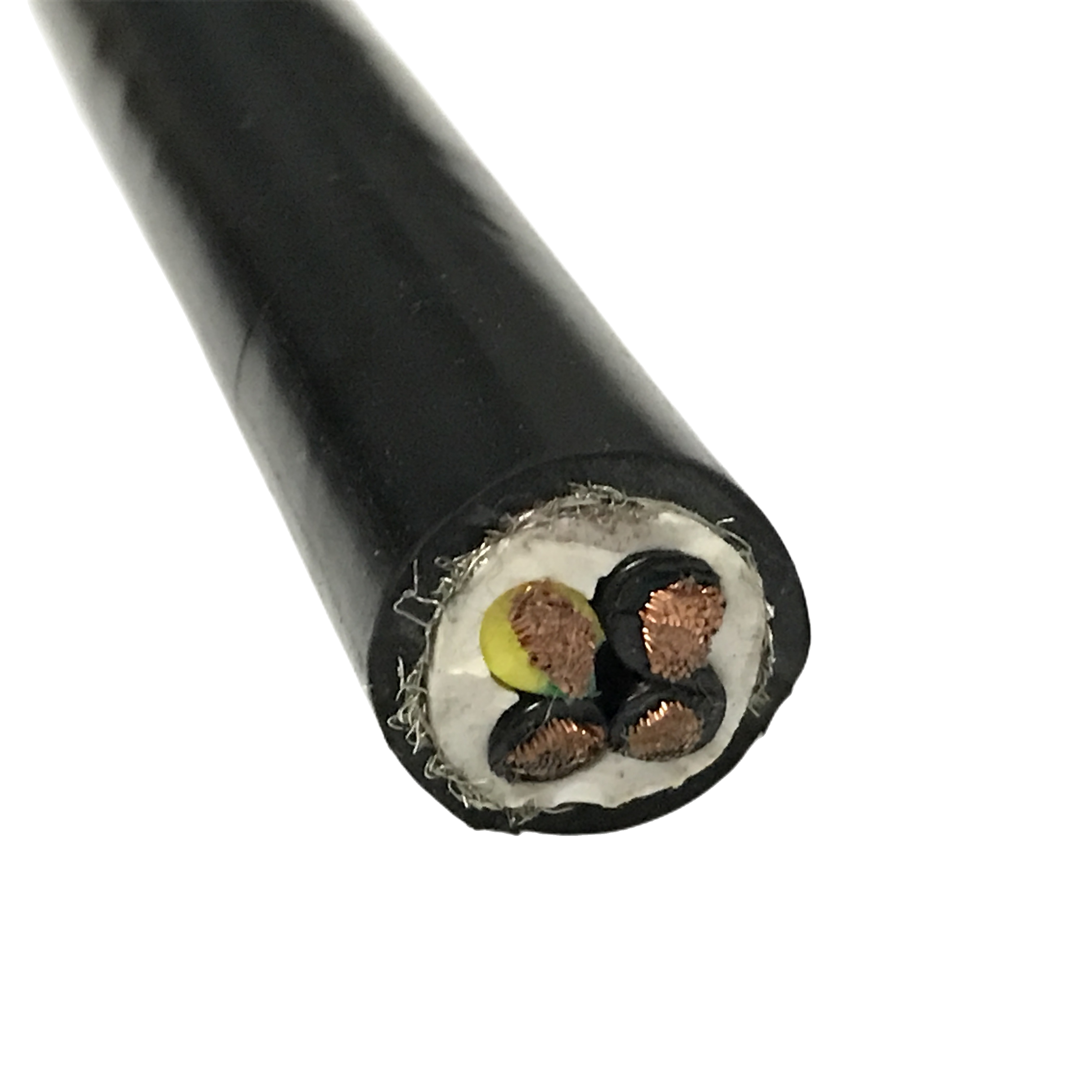
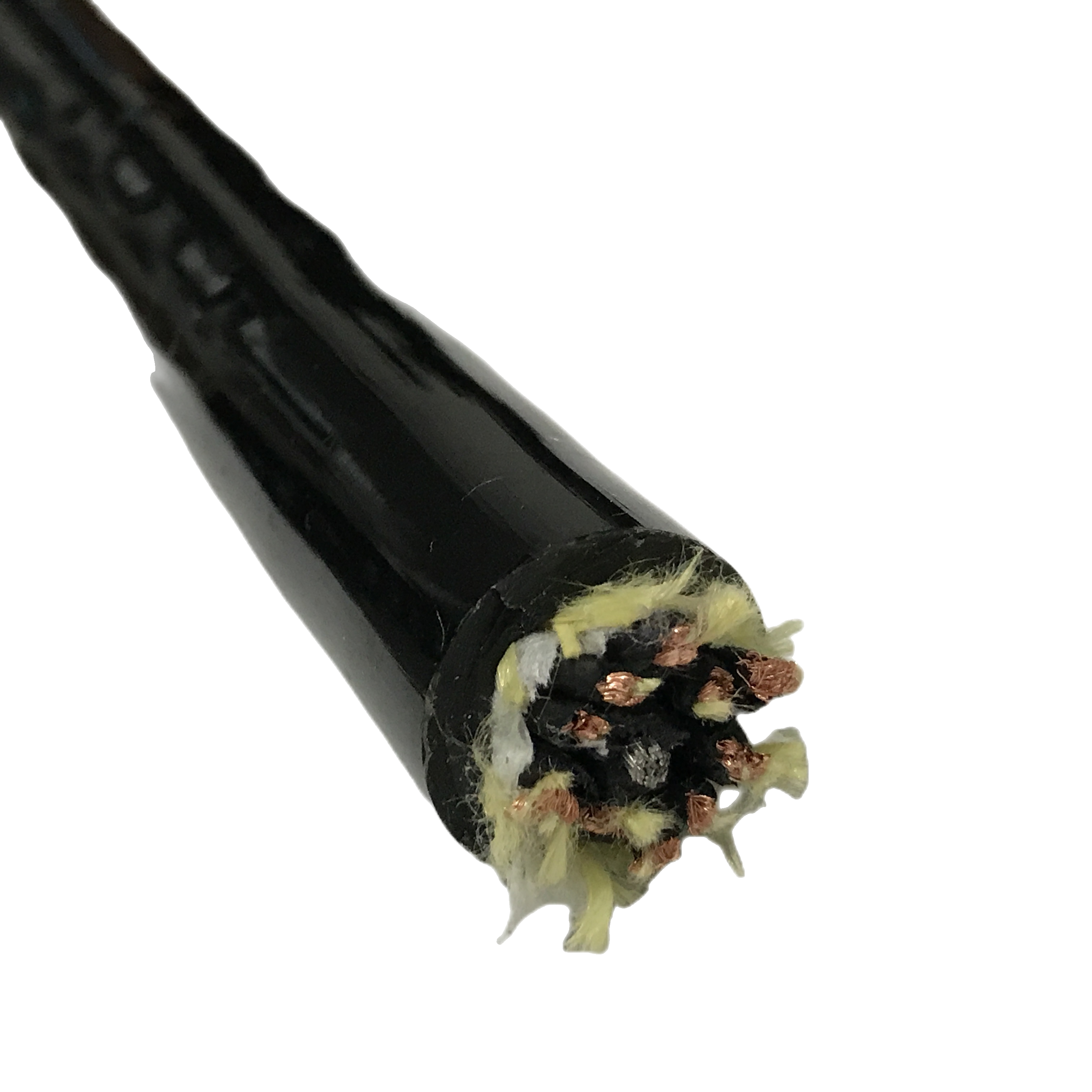
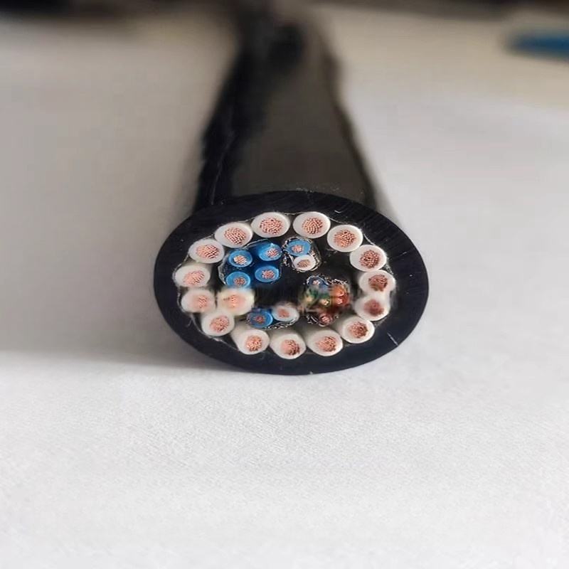
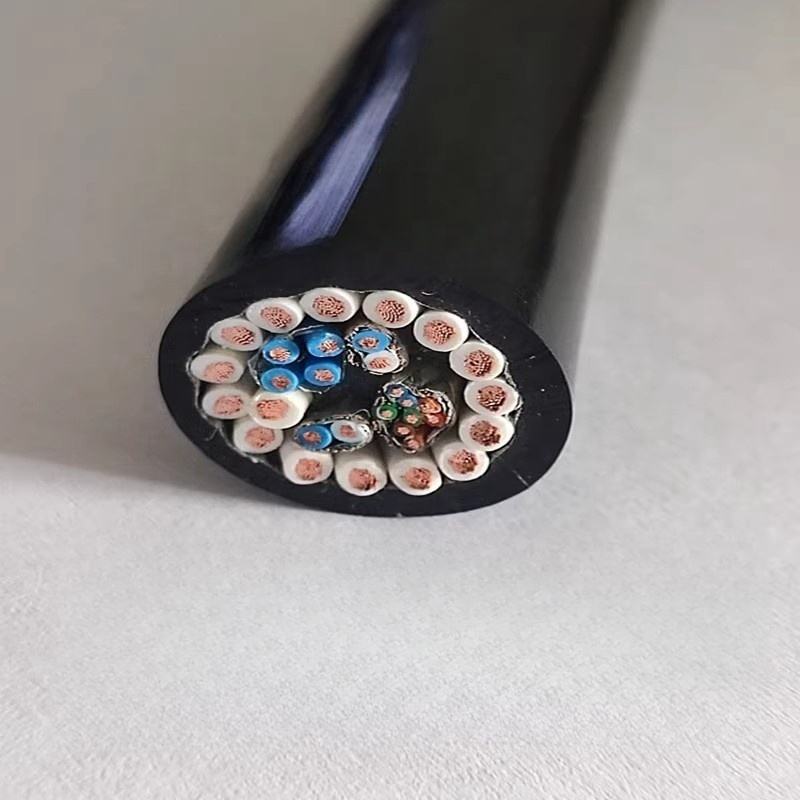
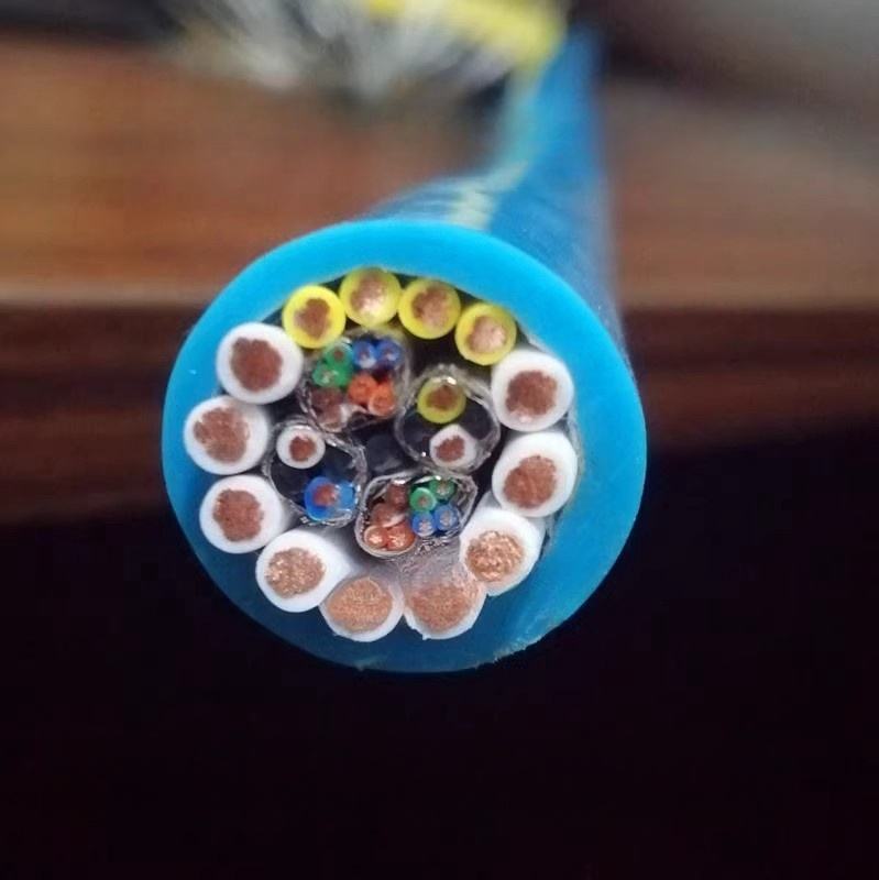
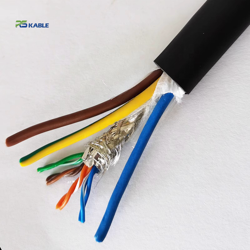
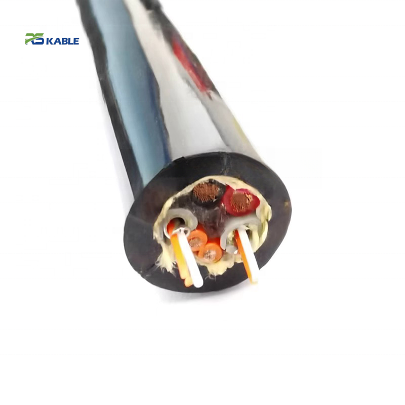
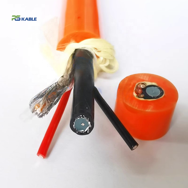
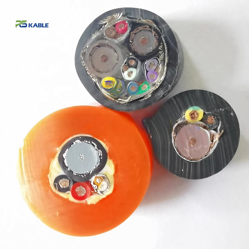
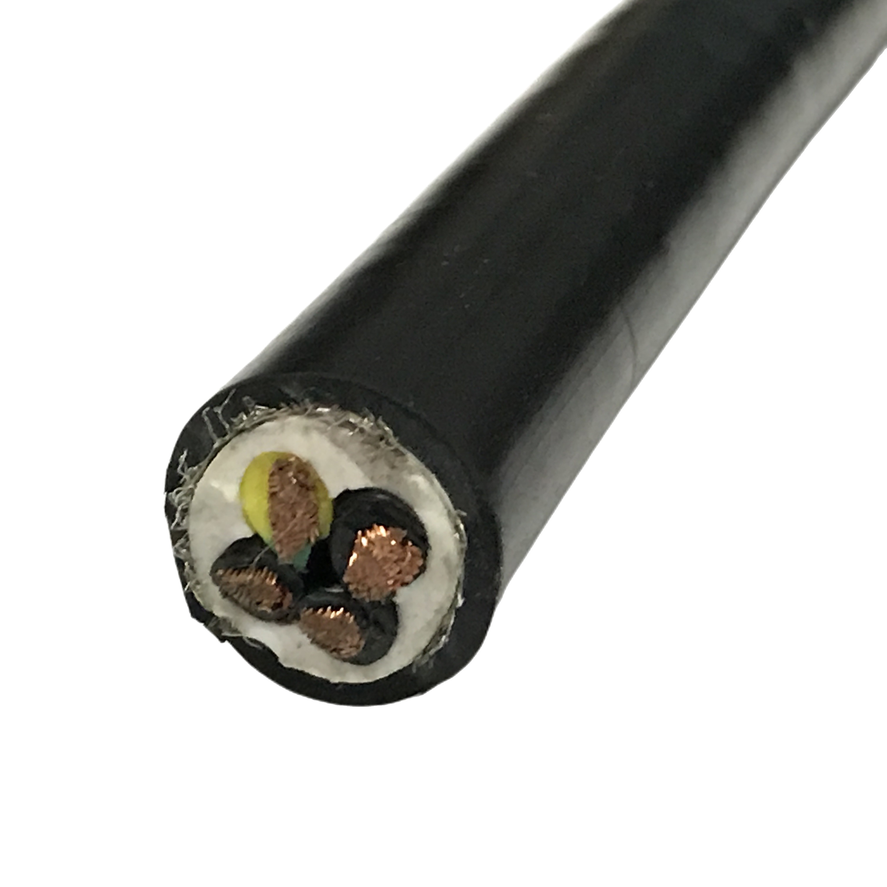
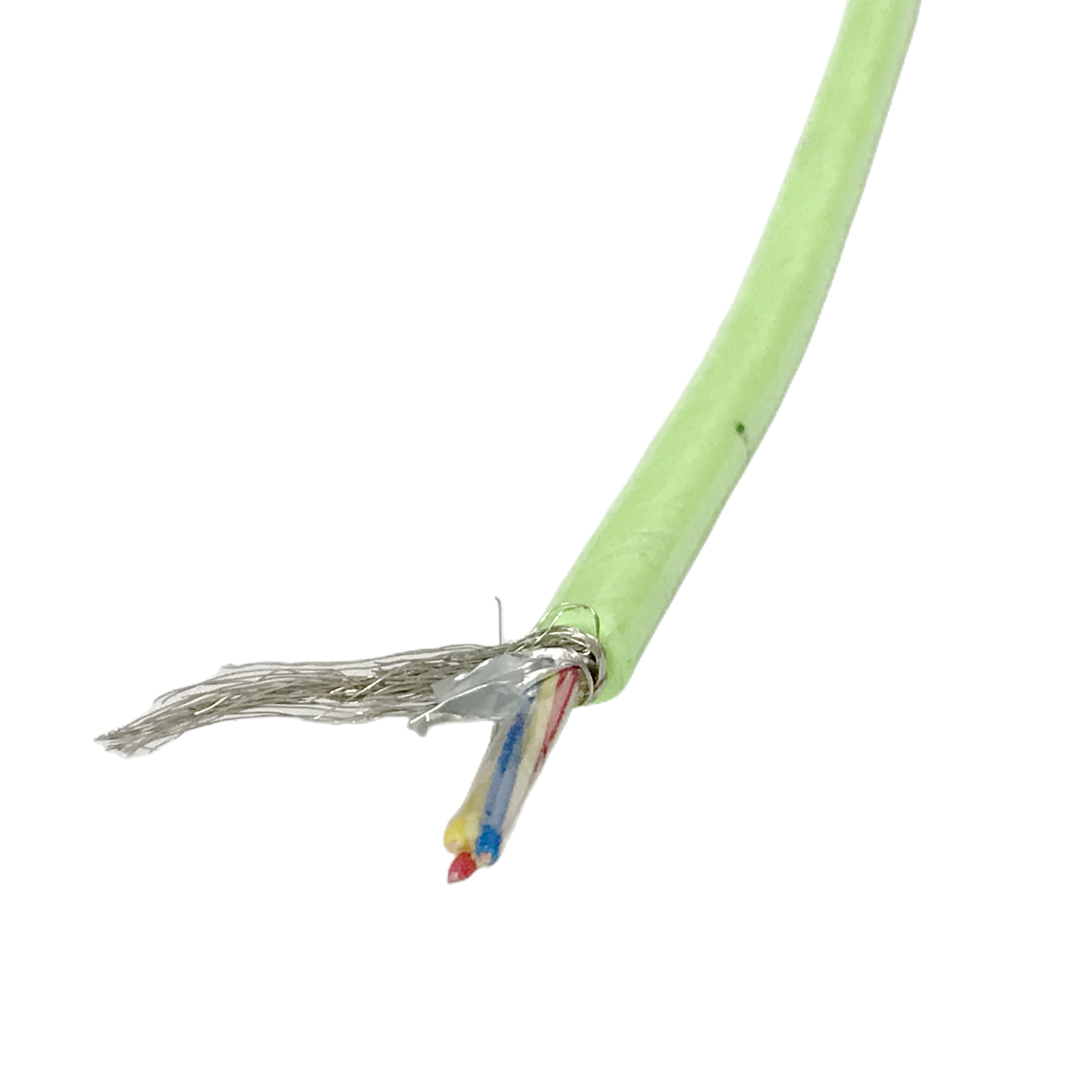
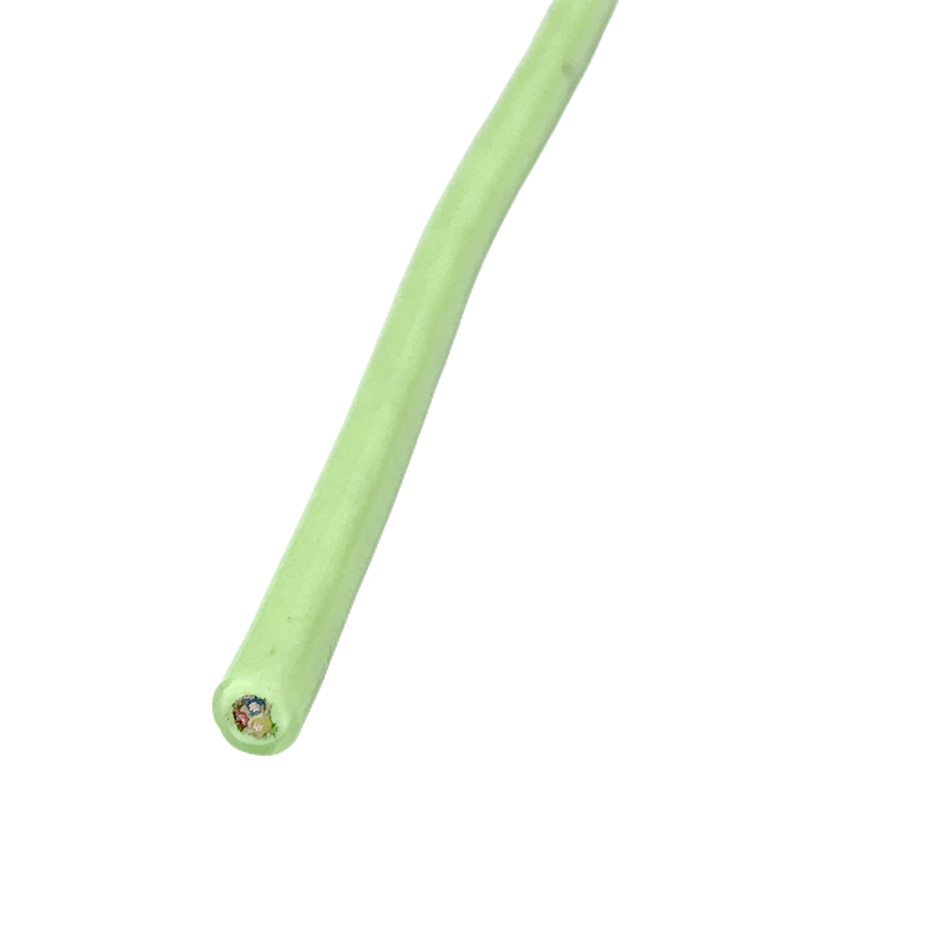
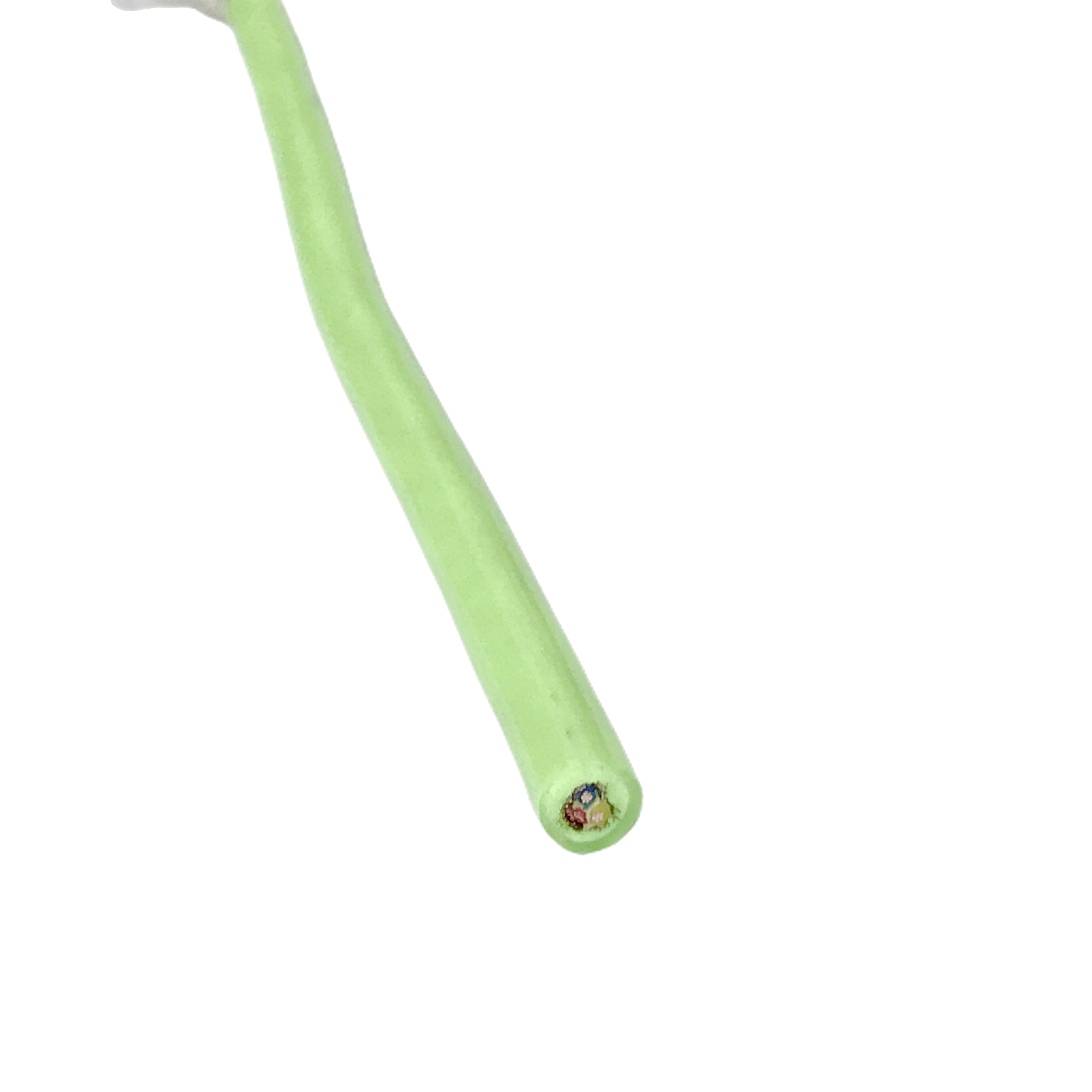
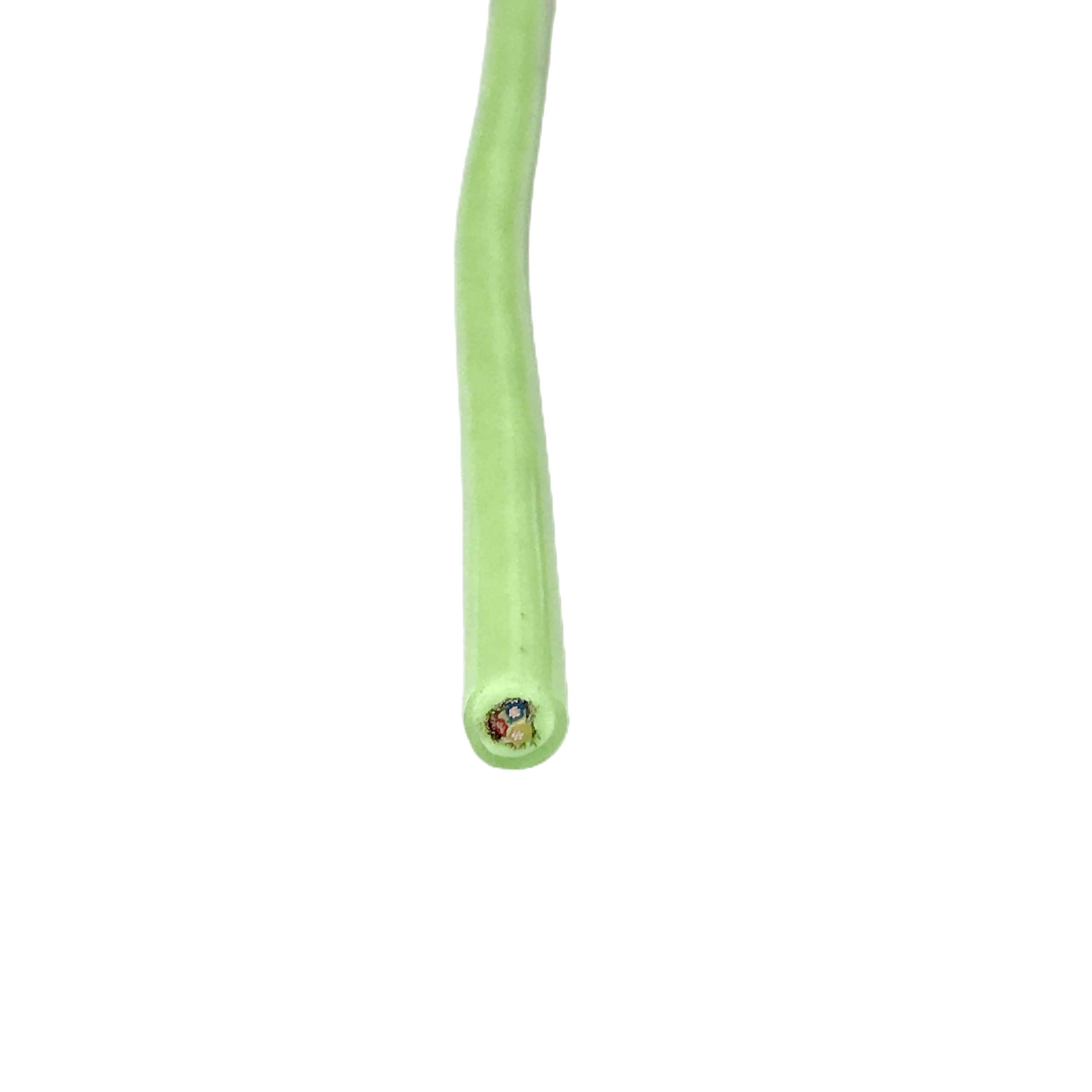
Construction: Three-Zone Architecture and Isolation Design
Zone A: optical element at the neutral axis
The fibre tubes are positioned within 1.5 mm of the cable’s geometric centreline — the neutral axis where bending strain is zero for a cable bent in any direction. At a 291 mm effective bend radius in DN200 pipe (worst case), a 1.5 mm fibre displacement produces 0.52% strain — 48% below the G.657.A1 short-term strain limit of 1.0%. Fibre placement is verified by X-ray cross-section inspection on 1-in-20 production length samples, with displacement measurement traceable to Rousheng geometry standard CCS-001, 2024.
Zone B: power element with twisted return
Power conductors are deployed as twisted live-and-return pairs with a maximum pitch of 20 mm. Twisting the live and return conductors reduces the magnetic field at any external point by cancelling the opposing fluxes — at 10 mm distance from a 20 mm pitch twisted pair carrying 5 A, residual field is reduced by approximately 35 dB compared with untwisted conductors. XLPE insulation on all power conductors is specified for two reasons beyond thermal rating: XLPE has a lower dielectric constant (εr ≈1.5) than PVC (εr ≈3.0), reducing the capacitive coupling from power to control pairs by approximately 50% per unit length.
Interzone PTFE separator
A 0.05 mm PTFE tape separator wraps the complete power element bundle before the control pairs are applied. PTFE has essentially zero dielectric loss at frequencies up to 10 GHz, so the separator adds no attenuation to the signals it isolates. Its primary function is physical: it prevents the power conductor XLPE insulation from making direct contact with the control pair foil screens, which would create a capacitive coupling path that bypasses the per-pair screening. The combination of PTFE separator + per-pair foil + overall braid achieves the measured 60 dB power-to-control isolation (see Section 7, Technical Parameters).
Zone C: control pairs and overall shielding
Control signal pairs use a three-tier architecture. Tier 1: per-pair aluminium-polyester foil (100% coverage) with tinned copper drain wire. Tier 2: overall foil wrap over the complete control pair bundle. Tier 3: tinned copper braid (≥90% optical coverage) over the complete cable assembly. The overall braid is the primary RF and radiated EMI rejection layer; it also provides the low-impedance current return path required for both-end shield bonding in EtherCAT installations. Transfer impedance of the overall braid: ≤20 mΩ/m at 10 MHz (IEC 62153-4-7 triaxial method).
|
Layer |
Specification |
Isolation Function |
Verified By |
|
SM G.657.A1 fibre |
Loose-tube gel-filled PBT; ±1.5 mm from centreline |
Immune to all EM interference (optical waveguide) |
X-ray cross-section; OTDR per fibre per drum |
|
XLPE power insulation |
Cross-linked PE, +90°C, 300/500 V; live+return twisted @ ≤20 mm pitch |
Minimises magnetic field generation; low dielectric constant reduces capacitive coupling |
HiPot 2,000 V AC/5 min per drum; twist pitch measured inline |
|
PTFE interzone separator |
0.05 mm PTFE tape, 100% coverage, zero dielectric loss |
Physical isolation; prevents XLPE-to-foil direct contact coupling |
Visual inspection; isolation measured on composite assembly |
|
Per-pair Al foil screen |
100% foil coverage + tinned Cu drain wire per pair |
Tier-1 EMI rejection; drain wire provides low-impedance shield return |
Coupling attenuation ≥60 dB @ 16 kHz measured on composite |
|
Overall tinned Cu braid |
Optical coverage ≥90%; transfer impedance ≤20 mΩ/m @ 10 MHz |
Tier-3 RF rejection; ground reference for shield bonding |
IEC 62153-4-7 triaxial method; per batch test |
|
Polyether PUR jacket |
PTMEG-based; Shore A 85±3 standard / 90±2 HD; OD ±0.15 mm |
Mechanical protection; waterproof barrier |
IP68 per drum; OD laser micrometer at 200 mm intervals |
|
Kevlar 49 tensile |
Counter-wound, dual-layer; self-rotation ≤0.3°/m at rated load |
No torque contribution to robot yaw |
Per-drum 10 m hanging test with calibrated load cell |
Technical Parameters
EMI isolation — verified measurements
The following EMI measurements are worst-case values across production batches, not type-approval best-case results. Test conditions are stated for each parameter.
|
Parameter |
Measured Value |
Test Conditions (n = sample size) |
Standard / Report |
|
Power-to-control coupling attenuation @ 16 kHz |
≥60 dB (worst-case across n=12 production samples) |
50 m RST-CPC-M; 16 A motor load on 2×1.5 mm² power cores; RS-485 pair at Zone C; measured per IEC 61000-4-6 adapted |
Rousheng PCQ-CPC-001, 2024 |
|
Power-to-control coupling @ 32 kHz (VFD 2nd harmonic) |
≥58 dB |
Same test conditions |
Rousheng PCQ-CPC-001, 2024 |
|
Overall braid transfer impedance @ 10 MHz |
≤20 mΩ/m |
IEC 62153-4-7 triaxial method; n=6 cable lengths per compound batch |
IEC 62153-4-7 |
|
RS-485 CMRR (motor stall transient, 12 A, 2 ms) |
Induced noise on pair: 85 mV peak (below 200 mV RS-485 threshold) |
Motor stall simulation, 100 m RST-CPC-M; measured at cable far end; n=6 samples |
Rousheng CPC-ET-001, 2023 |
|
EtherCAT frame error rate at 100 m with 16 A motor load |
0 errors in 10⁹ frames |
100 m RST-CPC-M-EC; simultaneous 16 A motor load; 24 h continuous test; n=3 cables |
Rousheng CPC-ET-002, 2024 |
|
Fibre attenuation change at rated bend (291 mm radius, 10 turns) |
≤0.01 dB/km change from straight-cable baseline |
10 turns at 291 mm radius; measured before and after; n=6 fibres from 3 different drums |
IEC 60793-2-50; IEC 60794-1-2 Method E10 |
Optical parameters
|
Parameter |
Specification |
Standard |
|
Fibre type |
ITU-T G.657.A1 bend-insensitive SM |
ITU-T G.657.A1:2016 |
|
Attenuation @ 1,310 nm |
≤0.36 dB/km |
IEC 60793-2-50 |
|
Attenuation @ 1,550 nm |
≤0.20 dB/km |
IEC 60793-2-50 |
|
PMD |
≤0.04 ps/√km |
IEC 60793-2-50 |
|
Min bend radius (G.657.A1) |
10 mm long-term; 7.5 mm short-term |
ITU-T G.657.A1 |
|
Fibre placement tolerance |
±1.5 mm from cable centreline (X-ray verified) |
Rousheng CCS-001, 2024 |
|
OTDR trace supplied |
1,310 + 1,550 nm per fibre per drum; .SOR + PDF; NIST-traceable calibration |
Factory measurement; calibration certificate included |
Electrical and mechanical
|
Parameter |
Value |
Standard / Source |
|
Power conductor cross-section |
0.75–4.0 mm² OFC, IEC 60228 Class 5 |
IEC 60228:2004 |
|
Power HiPot |
2,000 V AC / 5 min |
IEC 60502-1 Cl.17 |
|
Insulation resistance |
≥200 MΩ·km |
IEC 60502-1 Cl.18 |
|
RS-485 pair impedance |
120 Ω ±10 Ω |
IEC 61156-5; EIA-485 |
|
EtherCAT pair impedance |
100 Ω ±5 Ω |
ETG.1600 |
|
Kevlar tensile rating |
0.8–4.0 kN per model; tested to 1.5× rated load |
ASTM D7269; load-cell certificate per drum |
|
Self-rotation @ rated load |
≤0.3°/m (n=24 production drums, 2024) |
Rousheng RCTT-001; 10 m hanging test, calibrated load cell |
|
OD tolerance |
±0.15 mm (inline laser micrometer, 200 mm intervals) |
Rousheng QCP-CPC-001, 2024 |
|
IP rating |
IP68 at rated depth per model; tested per drum |
IEC 60529 |
|
Operating temperature (standard) |
−40°C to +80°C |
IEC 60811-501 |
|
Operating temperature (HT model) |
−40°C to +120°C |
IEC 60811-501; HT compound qualification |
|
Water-blocking migration |
≤0.5 m from cable breach (gel fill + SAP tape) |
IEC 60794-1-2 Method F5B |
|
Jacket polyether PUR hydrolysis |
≤2% tensile change, 5,000 h at 23°C (pH 2.5–12) |
ISO 175; Rousheng CP-CPC-001, 2024 |
Verified Industrial Deployments
Client company names withheld. Deployment context, technical measurements, and outcome data verified by client engineering contacts. Available for verification under NDA.
|
Deployment |
Operational Context |
Cable Specified |
Problem Solved |
Verified Outcome |
|
Water utility, DN150 water main rehabilitation programme, central Taiwan (2022–2024) |
AI-assisted crack detection (ResNet-based model, minimum detectable crack width 0.3 mm); 4K camera; EtherCAT control bus; 12 inspection robots operating simultaneously; 3 inspections per pipe segment before and after CIPP lining; 180 m target range |
RST-CPC-M-EC, 18 mm OD, 4×SM G.657.A1, EtherCAT + RS-485, 2.0 kN Kevlar, 200 m per cable; 12 cable sets total |
Previous 3-cable system (75 Ω coax + power pair + RS-485) could not fit in DN150 bore alongside robot chassis in the utility’s tight-tolerance robot specification. 4K video required fibre: coax limited to 150 m at HD-SDI quality, below the 180 m programme target. |
OTDR at commissioning: 0.22 dB/km @ 1,550 nm (all 48 fibres across 12 cables). EtherCAT: 0 CRC errors in 14-month operational period (Rousheng remote monitoring data). AI detection rate: 94.2% of ground-truth cracks ≥0.3 mm width (programme benchmark: ≥90%). 62 km of main surveyed 2022–2024. |
|
Gas distribution operator, DN200 polyethylene gas main, southern Germany (2023) |
ATEX Zone 1 IIB T4 Gb inspection robot; 4K fibre-optic video; 150 m target range in CH₄ atmosphere; IECEx-certified robot system; inspection frequency: monthly per regulatory requirement |
RST-CPC-S (ATEX Zone 1 compound), 14 mm OD, 2×SM G.657.A1, RS-485, 1.2 kN Kevlar, 160 m |
ATEX system review: SM fibre carries no electrical current and creates no ignition risk — the optical elements required no ATEX assessment. Power and control conductors in Ex-i (intrinsically safe) circuit. Eliminating separate video coax removed one additional cable from ATEX scope. |
ATEX/IECEx certificate package accepted by TÜV Rheinland for robot system approval. 145 m range achieved in DN200 PE gas main (target: 150 m; 3.3% below target from 0.8 kN/100 m higher-than-calculated pipe roughness in older sections). 28 km of main inspected 2023. |
|
Nuclear BWR plant, feedwater pipe inspection, Olkiluoto, Finland (2023–2024) |
Radiation-hardened remotely operated robot; DN100 stainless steel feedwater pipe; 60 m target range; estimated 30–40 Gy per inspection run based on plant dose mapping; inspection frequency: biannual; 10 planned inspection runs |
RST-CPC-OEM (RH compound, 500 Gy gamma rated, halogen-free PUR), 4×SM G.657.A1, RS-485 + CANbus, 1.5 kN Kevlar, 70 m; all-dielectric fibre video path |
Nuclear safety assessment: all-dielectric fibre video path (no electrical conductor in the video signal circuit between robot and topside) eliminated one potential electrical fault mode from the safety case. Halogen-free jacket compound required by Finnish nuclear site electrical code to prevent HF/HCl gas generation in cable fire scenario. |
Post-irradiation jacket mechanical test at 5 inspection runs (est. 150 Gy cumulative): elongation 338% (target >300%); Shore A 84 (target 85±5). OTDR at 5 runs: 0.24 dB/km @ 1,550 nm (vs 0.20 dB/km at commissioning; within budget). Nuclear safety authority accepted cable for planned 10-run inspection programme. |
|
Robot OEM manufacturer, pipeline inspection platform, Shenzhen, China (2022–2024) |
OEM cable for 4K pipeline inspection robot platform targeting DN100–DN300 market; annual production volume: 1,200 cable sets/year; warranty return rate for previous cable: 3.8% from connector seal failures within first 200 inspection runs per robot |
RST-CPC-M factory-terminated: 4×SM G.657.A1 with LC/APC pigtails at robot end + 8-pin Lemo at topside; moulded PUR strain relief at both ends; IP68 rated at connector interface |
Root cause of previous failures: silicone rubber connector boot delaminating from TPU cable jacket at the robot entry point under cyclic push/pull stress. Moulded PUR strain relief (same compound as jacket, chemically bonded during moulding) eliminated the material interface. |
Warranty return rate for cable-related failures: 0.32% across 1,200×16 months ÷ 12 = 1,600 cable sets shipped. Estimated annual warranty saving: CNY 580,000. OEM adopted RST-CPC-M as standard platform cable 2023. |
|
Municipal wastewater authority, DN300 combined sewer interceptor survey, Yorkshire, UK (2023–2024) |
Heavy tracked robot with 4K camera, sonar profiling (250 kHz), and laser diameter measurement; three simultaneous high-bandwidth data streams; inspection frequency: quarterly; 300 m target range; NASSCO PACP compliance required |
RST-CPC-L-FB, 22 mm OD, 8×SM G.657.A1 (4 fibres downlink video + laser; 4 fibres uplink sonar + IMU), EtherCAT + CANbus, 3.0 kN Kevlar, 320 m |
Previous composite copper cable (4K coax + power + RS-485) reached 10 Gbit/s capacity limit at 80 m — insufficient for 300 m range. Three simultaneous streams (4K at 12 Gbit/s, sonar at 1.5 Gbit/s, laser IMU at 100 Mbit/s) required 8 SM fibres in 4+4 bidirectional configuration. |
All three data streams simultaneously at 300 m: OTDR loss 0.21 dB/km across all 8 fibres at 1,550 nm. EtherCAT: 0 CRC errors in 14-month programme. NASSCO PACP condition grade accepted for all 48 km of interceptor surveyed. Inspection programme completed 6 weeks ahead of contract schedule. |
FAQ — Procurement Engineers & Robot OEM Teams
Q1: What is the minimum bend radius of composite pipeline cable in a 90° elbow fitting?
The minimum bend radius for dynamic service (repeated robot transit) is 10× cable OD. For RST-CPC-M (OD 18 mm), this is 180 mm. A standard DN200 90° long-radius elbow fitting has a centreline radius of 300 mm — well above the 180 mm limit. Standard short-radius elbows (1D bend, radius = DN = 200 mm) also exceed this limit for RST-CPC-M. The practical constraint in most inspections is not the elbow fitting but the straight pipe section where the cable must be pushed without buckling. Contact our engineering team with your specific elbow geometry for a strain calculation at the fibre displacement tolerance for your cable model.
Q2: How do I specify the correct fibre count for a multi-sensor inspection robot?
Calculate the total data rate requirement for all sensors simultaneously, then divide by the per-fibre capacity at your cable run length. For a 300 m run with SM G.657.A1 (10GBASE-LR SFP): each fibre carries 10 Gbit/s, limited only by the SFP transceiver speed. A robot with 4K video (12 Gbit/s), sonar (1.5 Gbit/s), and IMU (100 Mbit/s) needs: ceiling(12/10) = 2 downlink fibres for video, 1 downlink for sonar, 1 uplink for IMU data — minimum 4 fibres. Add 2 spare fibres for redundancy and future sensor expansion. RST-CPC-M (4 fibres) is the minimum; RST-CPC-L (8 fibres) is recommended for robots with planned sensor upgrades.
Q3: Can I use this composite cable in an ATEX Zone 1 gas main without a full Ex cable assessment?
The optical fibre elements (SM G.657.A1 glass fibre in gel-filled PBT tubes) are inherently ATEX-safe: they carry no electrical energy and cannot create an ignition source. They require no Ex assessment. The power conductors and control signal pairs carry electrical energy and must be either Ex-e (increased safety) or Ex-i (intrinsically safe) to meet ATEX Zone 1 requirements. RST-CPC-OEM supplies IECEx Zone 1 IIB T4 Gb compound on the jacket, which is required for the cable outer jacket in Zone 1. The complete ATEX/IECEx documentation package for the robot system must be prepared by a competent person; Rousheng provides the cable IECEx certificate as one document in that package.
Q4: What connector type is best for the robot-end fibre termination at IP68 depth?
For depths to 5 m (most pipeline inspection applications): field-assembled LC/APC or SC/APC connectors in an IP68-rated sealed splice box at the robot cable entry point. For depths to 30 m (larger robots in flooded pipes): wet-mate optical connectors (SubConn OFOC series, Teledyne BIRNS 450 series, or equivalent) are factory-installed with the cable by Rousheng. Wet-mate connectors add approximately 0.3–0.5 dB insertion loss per mating pair; include this in your fibre link budget when specifying the cable. For in-pipe connector mating (e.g. tool-change systems), specify the neutral-buoyancy lubricant compatible with the connector O-ring material to ensure seal integrity at full depth.
Q5: My robot uses a 48 VDC motor. Does the composite cable rating change?
RST-CPC power conductors are rated at 300/500 V — a 48 VDC supply is well within this rating. The more important question at 48 VDC is voltage drop: at higher voltage, the same power is delivered at lower current, reducing VD for the same conductor cross-section. A 5 A motor at 48 V draws 240 W; the same 240 W at 24 V draws 10 A. At 200 m run length with 1.5 mm² conductors: VD at 10 A = 29.6 V (123% of 24 V supply — impossible); VD at 5 A at 48 V = 14.8 V (31% of 48 V supply — marginal). For 48 VDC at 200 m, specify 2.5 mm² conductors (RST-CPC-L or XL) giving VD = 9.1 V (19% of supply — within acceptable range). Rousheng provides a VD calculation with every technical enquiry.
Q6: What documentation is provided with each RST-CPC production drum?
Standard per-drum documentation package: OTDR trace (1,310 + 1,550 nm per fibre, .SOR + PDF, NIST-traceable calibration); HiPot certificate (2,000 V AC / 5 min, all power and control conductors); Kevlar tensile load certificate (tested to 1.5× rated load, calibrated load cell); torque balance test result (°/m at rated load, 10 m hanging test); OD measurement record (laser micrometer readings at 200 mm intervals, start-mid-end summary); IP68 immersion test certificate (at rated depth); polyether PUR compound batch certificate (Shore A, tensile, elongation, Taber abrasion); RoHS 2 and REACH SVHC declaration. IECEx certificate and nuclear traceability package on request.
Manufacturer Credentials — Shanghai Rousheng Composite Cable
|
Production & test capabilities Three-zone co-extrusion: fibre, power, control cabled simultaneously in one production pass OTDR per fibre per drum: 1,310 + 1,550 nm; .SOR + PDF; NIST-traceable calibration X-ray cross-section inspection: fibre placement verified on 1-in-20 length samples EMI coupling test per batch: PCQ-CPC-001 protocol; worst-case n=12 samples reported Torque balance: per-drum 10 m hanging test, calibrated load cell (RCTT-001) IP68: per-drum immersion test at rated depth; certificate with every drum Factory fibre termination: LC/APC, SC/APC, SubConn OFOC, Lemo, custom wet-mate |
Certifications ISO 9001:2015 quality management system CE marking — LVD Directive 2014/35/EU RoHS 2 / REACH SVHC compliance per shipment IECEx Zone 1 IIB T4 Gb compound (ATEX/IECEx gas main applications) Nuclear material traceability package: batch-level raw material certification (RH models) CNAS-accredited third-party lab reports on request OEM qualification package: all per-drum certificates + compound TDS + test reports |
Request a Composite Pipeline Robot Cable Technical Proposal
|
Contact Email: Jerry@rstlkable.com Phone: +86-021-50759965 Mobile: +86-13482197396 Address: No. 2591 Fengzhe Road, Fengxian District, Shanghai, China Proposal within 24 hours. Full per-drum documentation package included with every order: OTDR, HiPot, Kevlar load, torque balance, OD record, IP68 certificate, compound batch cert. |
Include in your enquiry 1. Robot type and pipe diameter (DN) 2. Fibre count and data architecture (video-only, bidirectional, WDM, multi-sensor) 3. Control protocol: RS-485, CANbus, EtherCAT, PROFINET, or PoE 4. Motor voltage (V) and rated current (A) 5. Target inspection range (m) and pipe environment 6. Connector type at robot end and topside end 7. Special requirements: ATEX/IECEx, nuclear, HT, radiation-hardened, halogen-free We return: fibre strain calculation for your pipe geometry, VD check, protocol feasibility at your cable run length, EMI isolation confirmation, and model recommendation. |