Coiled Ethernet + Power Cable | Spring-Type Retractable Cable for Industrial Equipment
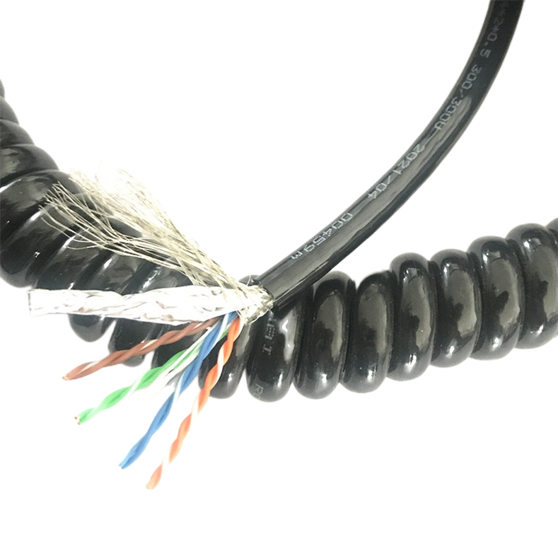
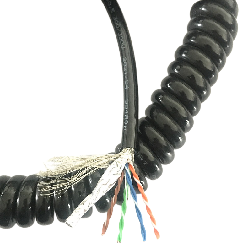
This spring-return coiled cable combines Cat5e/Cat6 Ethernet and power in a durable PUR or TPE jacket, eliminating the need for external retractors.
Key Benefits:
✅ Self-retracting design, no retractor required
✅ ≥5 million flex cycles for long service life
✅ Clean, space-saving cable management
✅ Ideal for robotics, gantry, and automation systems
Custom configurations available to match your application.
Coiled Ethernet + Power Cable | Spring-Type Retractable Cable for Industrial Equipment
|
Cable type |
Data layer |
Flex life |
Jacket options |
|
Coiled / spring-return hybrid |
Cat5e or Cat6 (100–1000 Mbit/s) |
≥ 5,000,000 cycles (Cu cores) |
PUR · TPE · LSZH |
The Engineering Problem This Cable Solves
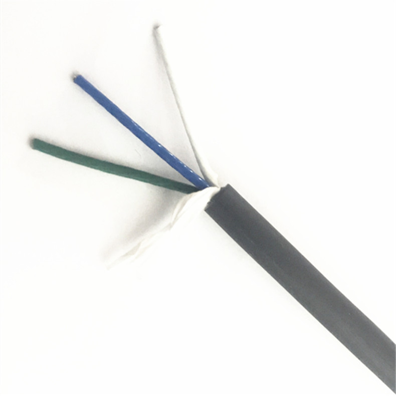
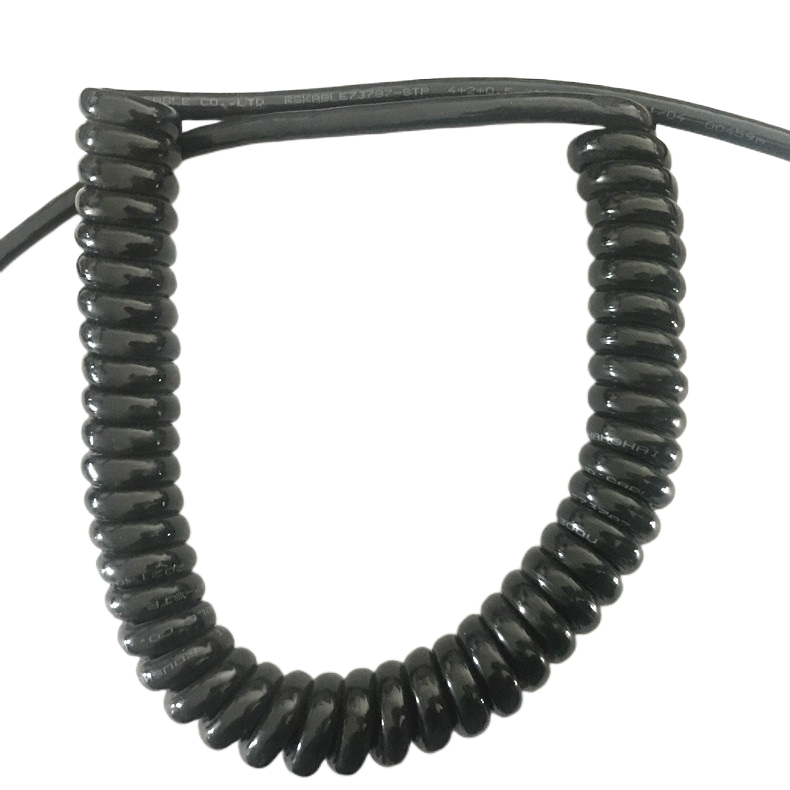
Industrial equipment that moves in short, repeated strokes — conveyor pick heads, gantry inspection arms, injection moulding robots, press-tending units — generates a cable management problem that straight cables handle poorly and drag chains handle expensively. The motion is too short for a full drag chain installation to be practical, but too frequent and too precise for a loose festoon loop to remain reliable.
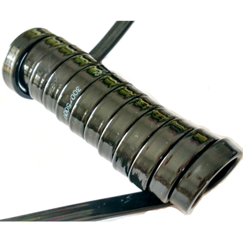
A coiled Ethernet power cable addresses this by storing the stroke energy in the coil geometry itself. When the moving element extends, the cable uncoils; when it retracts, the spring memory of the heat-set jacket pulls the cable back without any external guide or retractor mechanism. No trough, no festoon brackets, no chain lubricant schedule — just a cable that manages its own slack.
The design sounds simple. The manufacturing tolerance to make it reliable across five million cycles is not. This page documents what Rousheng builds into the RST-CE series, and why the details matter for equipment running two or three shifts per day.
How Spring-Type Retraction Actually Works — and Where It Fails
The term “spring-type retractable cable” is sometimes used loosely to mean any coiled cable. In manufacturing terms, spring memory is a specific physical property: the residual stress locked into the polymer jacket during a controlled heat-set process. Understanding this mechanism helps buyers evaluate supplier claims.
What happens during heat-settingThe jacket compound — PUR or TPE — is extruded around the finished core assembly while wound on a mandrel at the target coil diameter. The mandrel-wound assembly is then held at a compound-specific set temperature (typically 70–85 °C for PUR, 90–100 °C for TPE) for a defined dwell period. During this dwell, polymer chains relax into the coiled geometry and the material’s elastic memory is oriented around the helix axis. When released from the mandrel, the jacket retains this orientation permanently — barring thermal degradation or over-extension damage. The result is a cable that requires no mechanical spring or retractor: the jacket itself is the spring. |
Where the process goes wrongThree manufacturing shortcuts destroy coil memory without any immediate visible sign: › Insufficient dwell time. Cutting the heat-set cycle short leaves polymer chains in a partially relaxed state. The cable feels springy at delivery and loses 40–60% of its retraction force within the first 100,000 cycles. › Incorrect mandrel diameter. A mandrel diameter smaller than the final product specification introduces permanent residual tension that causes the extended cable to pull inward unevenly — creating a corkscrew rather than a clean extension. › Rapid quench cooling. Cooling the assembly too quickly freezes stress gradients across the jacket wall, producing a cable with strong retraction in one plane and weak retraction at 90° — a problem that only manifests under multi-axis loading in real applications.
Rousheng’s heat-set protocol specifies dwell time, mandrel diameter, and cooling rate as controlled process parameters — not operator judgment calls. Each production lot carries a heat-set log. |
|
PRODUCTION NOTE In 2022, we performed a side-by-side durability study with an identical core assembly jacketed using two different heat-set dwell times — our standard 4-hour protocol versus a 90-minute accelerated cycle. At 80,000 cycles, both cables were indistinguishable. At 500,000 cycles, the 90-minute cable had lost 38% of its retraction force and showed jacket micro-cracking at the coil peaks. The standard cable showed no measurable change. The study informed our current specification, which we do not compromise for delivery schedule. |
RST-CE Series: Complete Product Reference
Model designations, standard configurations, and performance parameters. All specifications are production-validated. Parameters marked with * are adjustable in engineered-to-order variants — see ordering section for lead time.
|
Model |
Ethernet |
Power cores |
OD (mm) |
Rest length* |
Max extension* |
Flex life |
Jacket |
|
RST-CE-110 |
Cat5e · 1 pr |
2 × 0.75 mm² |
8.0 ± 0.3 |
300 mm |
900 mm |
≥5M |
PUR |
|
RST-CE-120 |
Cat5e · 1 pr |
2 × 1.5 mm² |
9.5 ± 0.3 |
300 mm |
1,050 mm |
≥5M |
PUR |
|
RST-CE-130 |
Cat5e · 2 pr |
2 × 1.5 mm² |
11.2 ± 0.4 |
350 mm |
1,200 mm |
≥5M |
PUR / TPE |
|
RST-CE-210 |
Cat6 · 1 pr |
2 × 1.5 mm² |
10.8 ± 0.3 |
350 mm |
1,400 mm |
≥5M |
PUR / TPE |
|
RST-CE-220 |
Cat6 · 2 pr |
3 × 2.5 mm² |
14.0 ± 0.4 |
400 mm |
1,600 mm |
≥5M |
PUR / TPE |
|
RST-CE-230 |
Cat6 · 2 pr |
3 × 4.0 mm² |
16.5 ± 0.5 |
500 mm |
2,000 mm |
≥5M |
PUR |
|
RST-CE-300 |
Cat6 · 2 pr + RS-485 |
3 × 2.5 mm² |
15.8 ± 0.5 |
400 mm |
1,600 mm |
≥5M |
PUR |
|
RST-CE-C (ETO) |
Per spec |
Per spec |
8–24 mm |
Custom |
Custom |
Per design |
PUR/TPE/LSZH |
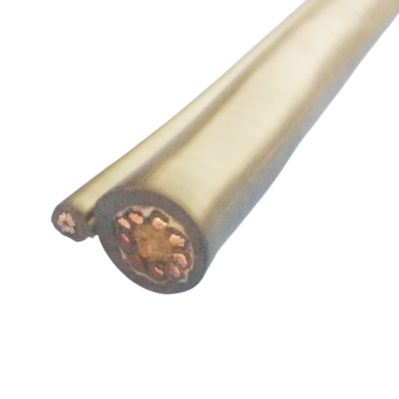
RST-CE-300 note: This model integrates a shielded RS-485 pair alongside the Cat6 Ethernet pairs, enabling simultaneous Modbus RTU device control and EtherNet/IP supervisory data on a single cable run. Useful in press-tending applications where the press controller communicates over RS-485 and the vision system uses GigE.
Complete Technical Specification
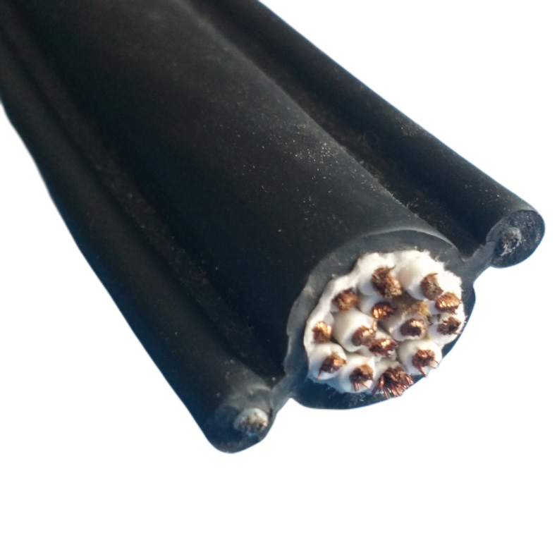
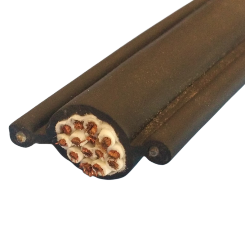
Conductor and Signal Layer
|
Parameter |
Specification |
|
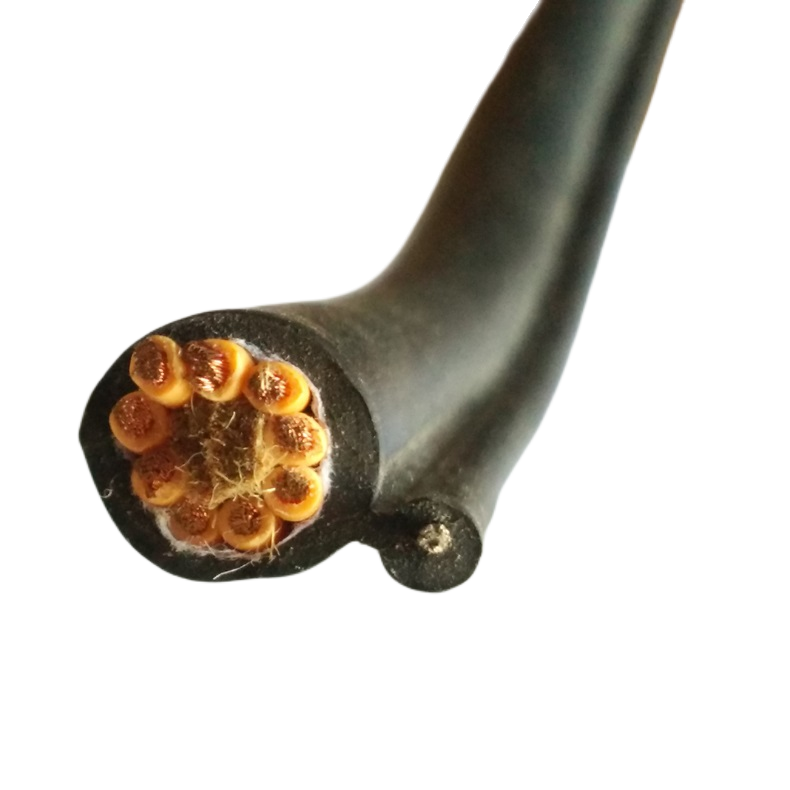
Power conductor |
Fine-stranded annealed copper per IEC 60228 Class 5; 0.75–4.0 mm² range |
|
Data conductor |
24 AWG bare copper, 7/0.20 mm stranding; controlled lay for impedance stability under flex |
|
Insulation — power |
XLPE (cross-linked polyethylene); 0.6 mm nominal wall; rated 300/500 V |
|
Insulation — data pairs |
Foamed FEP; controlled dielectric constant for 100 Ω impedance maintenance under coiled geometry |
|
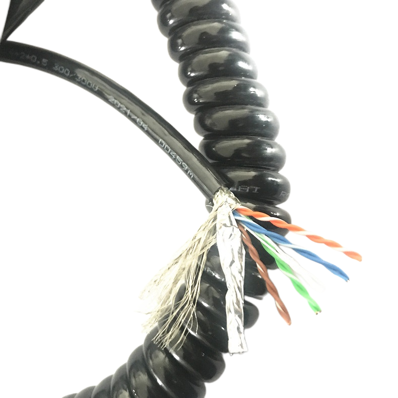
Pair shielding |
Individual AL/PET foil per pair + drain wire; 100% coverage |
|
Overall shielding |
Tinned copper braid; ≥ 90% optical coverage; transfer impedance < 25 mΩ/m @ 1 MHz |
|
Impedance |
100 Ω ± 6% across rated flex life; validated at 0, 500k, 2M, 5M cycle checkpoints |
|
Rated voltage (power) |
300/500 V AC; withstand test 2,000 V AC for 1 minute |
|
Max current (per core) |
0.75 mm²: 6 A | 1.5 mm²: 10 A | 2.5 mm²: 16 A | 4.0 mm²: 22 A (ambient 30 °C, free air) |
Mechanical, Thermal, and Chemical
|
Parameter |
Specification |
|
Flex life — copper models |
≥ 5,000,000 full extension/retraction cycles; criterion: no conductor open/short, impedance drift ≤ ±5%, jacket no visible cracking |
|
Coil spring-back time |
≤ 0.4 s from full extension to rest at 23 °C; ≤ 0.7 s at −20 °C |
|
Dynamic bend radius (coil) |
≥ 6 × OD |
|
Extension ratio (standard) |
1 : 3.0 to 1 : 4.0 (model-dependent); 1 : 5.0 ETO; ratio tolerance ± 8% |
|
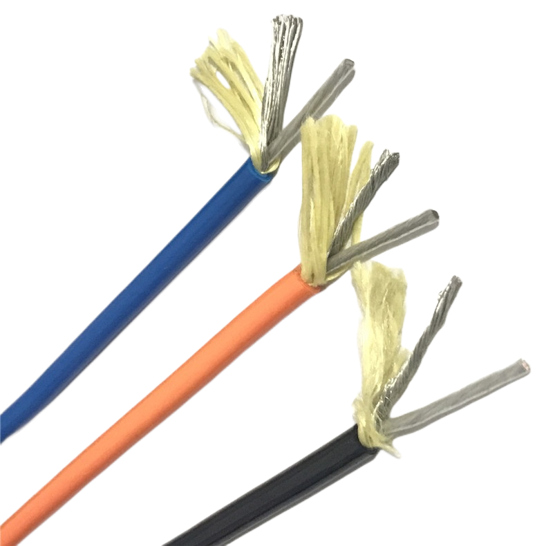
Tensile load (coil section) |
Max 25 N applied tension; Kevlar strength member available for ≤ 80 N (ETO) |
|
Temperature — PUR jacket |
−40 °C to +90 °C continuous; −55 °C cold-flex test (no cracking) |
|
Temperature — TPE jacket |
−30 °C to +105 °C continuous; food-grade extract per FDA 21 CFR 177.2600 (on request) |
|
Temperature — LSZH jacket |
−15 °C to +70 °C; IEC 60754-1 halogen content ≤ 0.5%; smoke density IEC 61034-2 ≥ 60% light transmission |
|
Oil resistance (PUR) |
IEC 60811-2-1 immersion (IRM 902 + IRM 903); tensile retention ≥ 80% after 7-day immersion |
|
UV resistance (outdoor option) |
UV-stabilised PUR compound; 1,000 h UV exposure per ISO 4892-2; no surface cracking |
|
Flame retardancy |
IEC 60332-1 (standard); IEC 60332-3-22 bunch test (LSZH option) |
|
Connector options |
RJ45 Cat5e/Cat6 plug (standard) · M12 D-coded (IP65/IP67) · M8 3/4-pin power · bare leads; overmolded on request |
Application Matrix: Where the RST-CE Series Is Specified
The table below maps specific machine types to the parameters that determine model selection. It is drawn from Rousheng’s application engineering records, not generic use-case descriptions.
|
Machine / system |
Stroke range |
Cycle rate |
Recommended model |
Selection rationale |
|
Pick-and-place unit (SCARA) |
80–300 mm |
120–300/min |
RST-CE-110 / 120 |
Short stroke, very high cycle rate; compact OD (8 mm) fits wrist housing; Cat5e sufficient for conveyor vision at 100 Mbit/s |
|
Injection mould handling robot |
200–800 mm |
20–60/min |
RST-CE-120 / 210 |
Moderate stroke; coolant mist environment requires PUR jacket rated for hydraulic fluid; Cat5e or Cat6 depending on camera resolution |
|
Press-tending robot |
300–1,200 mm |
15–40/min |
RST-CE-220 / 300 |
Longer stroke; 3 × 2.5 mm² handles servo brake release current; RST-CE-300 adds RS-485 for press controller integration without a separate cable |
|
Conveyor inspection gantry |
500–1,500 mm |
10–30/min |
RST-CE-210 / 220 |
GigE Vision camera demands Cat6; 2 × 1.5 mm² or 3 × 2.5 mm² for LED ring light + strobe controller power |
|
Semiconductor wafer handler |
50–200 mm |
60–150/min |
RST-CE-C (ETO, TPE) |
Clean-room protocol requires TPE jacket with low particle emission; standard models adapted with FDA-compliant TPE compound on request |
|
Welding positioner (short axis) |
100–400 mm |
30–80/min |
RST-CE-130 / 210 |
Weld spatter resistance: UV + heat-stabilised PUR; Cat5e / Cat6 for seam-tracking camera; extension ratio ≤ 1:3.5 preferred for short strokes |
|
Label applicator / inkjet marker |
50–250 mm |
100–400/min |
RST-CE-110 |
Highest cycle rate application in this range; compact OD and 0.75 mm² power cores are adequate for encoder + solenoid valve power; spring-back speed is critical — verified at 400 cycles/min on in-house rig |
|
FIELD DATA — Label applicator application (2024) A packaging machinery manufacturer replaced the festoon cable system on 24 inkjet marker units with RST-CE-110 coiled cables. The festoon system required repositioning every two weeks due to cable drape interference with product flow. After 18 months with the RST-CE-110 at an average 280 cycles per minute, zero cable replacements were required across all 24 units. The manufacturer estimates 3.5 hours per machine per year saved in maintenance time. |
Diagnosing Coiled Cable Failures: A Field Guide
When a coiled Ethernet power cable fails on a production line, the failure mode determines whether the root cause is the cable, the installation, or the application specification. The following diagnostic guide is based on Rousheng’s failure analysis records from returned cables and field service reports.
|
Observed symptom |
Most likely root cause |
Diagnosis method |
Corrective action |
|
Intermittent Ethernet packet loss during motion only |
Impedance drift in data pairs — conductor lay distortion |
TDR measurement at rest vs. at 50% extension. Look for impedance excursion > ±8% at specific cable positions |
Replace cable; specify Cat6 model with foamed FEP insulation for better geometry stability. Check extension ratio — over-extension accelerates this failure |
|
Cable does not retract fully — coil rest length has grown |
Coil memory loss — heat-set process failure or over-extension above rated ratio |
Measure rest length and compare to as-delivered spec. If >15% longer, coil memory is degraded |
Replace cable; verify application extension ratio does not exceed cable rating. Consider ETO model with higher rated ratio |
|
Jacket cracking at coil peaks |
Chemical degradation (incompatible fluid) or UV exposure beyond jacket rating |
Chemical exposure log — identify fluid type. UV-check: chalking or discolouration at jacket surface |
Switch to appropriate jacket compound (UV-PUR for outdoor; TPE for aggressive solvents). If oil-only, confirm PUR variant is specified |
|
Conductor open-circuit at strain relief transition |
Strain relief clamping force too high — jacket crushed, conductor broken at clamp edge |
Visual inspection at clamp point. Measure conductor resistance per core; failed core will show infinite resistance |
Reduce clamp torque to specified value. If housing design requires high clamp force, order ETO cable with Kevlar strength member taking load off conductors |
|
EMI noise on Ethernet during VFD operation |
Ground path discontinuity in shield — braid coverage below spec, or shield not connected at both ends |
Measure shield transfer impedance with LCR meter. Check both connector terminations for shield continuity |
Verify shield termination at both ends. If braid coverage is inadequate, upgrade to RST-CE-220 (≥90% braid coverage). Ensure cable ground is bonded to machine frame, not floating |
Installation Guidelines for Spring-Type Coiled Cables
These guidelines are drawn from Rousheng’s installation documentation. Correct installation extends cable life; incorrect installation causes failures that look like cable defects but are not.
Fixed-end mounting
- Mount the fixed end of the cable at a point that is directly in line with the axis of motion. An angular offset at the fixed mount introduces torsional stress with every cycle — the most common installation mistake we see.
- The cable exit angle from the fixed connector should be within ±15° of the axis of linear motion. Greater angles cause the coil to splay laterally rather than extend axially, reducing effective stroke and increasing fatigue rate.
- Fixed-end clamping force: apply to within the torque specification supplied with the cable. Over-clamping (a common instinct when “securing” the cable) crushes the jacket and creates a stress concentration at the clamp edge that fails within 50,000–100,000 cycles.
Moving-end connection
- Attach the moving-end connector to the machine element — not to the cable itself. Any intermediate loop of cable between the connector and the attachment point will flap at cycle speed and fail from fatigue at the unsupported bend.
- The moving-end connector should be rigidly fixed. A connector that is allowed to rotate or pivot relative to the attachment point allows the coil to twist — converting extension cycles into torsion cycles, which the cable is not rated for.
Clearance and routing
- Allow minimum 40 mm radial clearance around the coil at rest. The coil diameter increases by approximately 15% at full extension due to diameter-length coupling in the helix geometry. Routing through a tight channel that fits the resting coil will compress the extended coil against the channel wall.
- Do not route a coiled cable through a drag chain. The coil cannot function inside a constrained channel — see the comparison section for guidance on when to use a drag chain cable instead.
- If the application involves lateral as well as linear motion, consult Rousheng’s application engineering team. Multi-axis motion requires a cable designed for that loading path — typically an ETO model with a specific coil pitch and extension ratio combination.
Frequently Asked Questions
What is the difference between a coiled Ethernet power cable and a standard retractable cable reel?
A cable reel is a mechanical device — a spring-loaded spool that stores cable length and pays it out under tension. A coiled Ethernet power cable has no moving parts. The retraction force comes from the heat-set polymer jacket, and the cable is always the same physical length — it just occupies less linear space when coiled. This means no bearings to lubricate or seize, no slip rings to maintain signal continuity through, and no minimum retraction force that declines as the spring ages. The coiled cable is mechanically simpler and more reliable in continuous industrial use.
How do I specify the correct extension ratio for my stroke length?
The extension ratio (rest length : extended length) determines how much coil you need. Measure your maximum stroke — the distance the moving element travels. Add the cable routing geometry factor (typically +10–15% for non-straight paths). Divide by the rest length you have space for at the fixed end (usually 300–500 mm for most machine joints). If this ratio exceeds 1:4, consult us before ordering — ratios above 1:4 require specific heat-set tooling and are not standard catalog items.
Can the RST-CE cable operate at 1,000 cycles per minute?
Our standard ratings cover up to 400 cycles per minute — this is the rate at which the RST-CE-110 was validated on our in-house test rig for label applicator applications. At 1,000 cycles per minute, the dynamic forces on the coil and the connector terminations are significantly higher. This application requires an ETO design with a modified coil pitch, shorter rest length, and a different strain relief geometry. Please contact our engineering team with your cycle rate, stroke, and duty cycle — we have produced cables for cycle rates up to 800 cycles per minute and can advise on feasibility at higher rates.
Is the cable RoHS and REACH compliant?
Yes. All standard RST-CE models are RoHS 2 (EU Directive 2011/65/EU) and REACH SVHC compliant. Material declarations and substance reports are available for each model upon request. Halogen-free LSZH versions additionally comply with IEC 60754-1 halogen content limits and IEC 61034-2 smoke density requirements.
What lead times apply to standard versus custom models?
Standard RST-CE catalog models (RST-CE-110 through RST-CE-230) ship from stock or within 5 business days for quantities up to 200 meters (unterminated) or 50 assembled units. The RST-CE-300 (RS-485 hybrid) carries a 10-day lead time due to lower stock levels. Engineered-to-order (RST-CE-C) custom designs require 3–6 weeks from confirmed specification, depending on tooling requirements. Rush production for engineered items is available — discuss with our sales team.
Do you supply pre-terminated cables with M12 connectors for wet environments?
Yes. M12 D-coded (for Ethernet) and M12 A-coded (for power) connectors with IP67 overmolded backshells are available on all RST-CE models. Connector-to-connector lead length (the straight section from the coil to the connector face) is adjustable from 50 mm to 300 mm. For IP69K rated connections (washdown environments), we offer an alternative overmold compound rated for high-pressure cleaning — specify at order.
Request Technical Documentation or a Production Quote
Rousheng provides free pre-sales engineering support: application review, model selection confirmation, and custom parameter feasibility assessment, before any order commitment. To receive a response with specific technical and commercial recommendations rather than a generic catalogue reply, include the following in your enquiry:
- Machine type and the axis of motion the cable will serve
- Stroke length (mm) and maximum cycle rate (cycles per minute)
- Ethernet protocol and data rate; current draw per power core
- Chemical and temperature environment; any IP rating requirement
- Connector type preference; estimated annual volume
|
CONTACT Email: Jerry@rstlkable.com · WhatsApp / Phone: +86 134 8219 7396 · No. 2591 Fengzhe Road, Fengxian District, Shanghai, China |