Coaxial + Power Cable | Video and Power Combined Cable for CCTV & Industrial Systems
This hybrid cable combines 75 Ω coaxial and power cores in one design, ensuring stable video transmission with strong interference isolation.
Key Benefits:
✅ >74 dB power-to-video isolation for clear signal
✅ Supports RG-59, RG-6, and HD-SDI (up to 3.0 GHz)
✅ Compatible with standard BNC connectors
✅ Multiple jacket options: PVC, PUR, LSZH, direct burial, ATEX
Ideal for CCTV, PTZ systems, and industrial video applications, with custom configurations available.
Coaxial Power Cable | Video and Power Combined Cable for CCTV & Industrial Systems
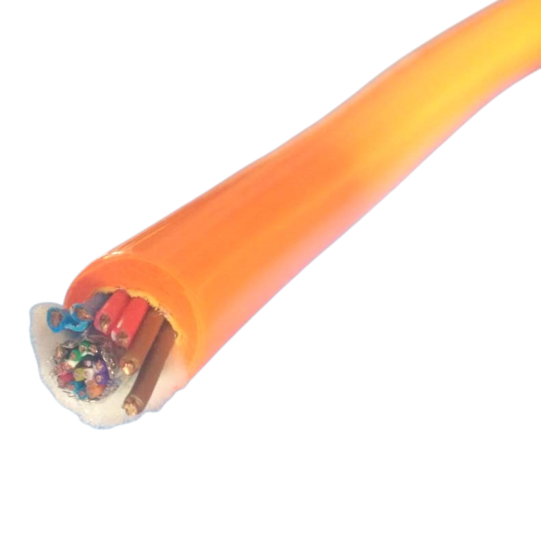
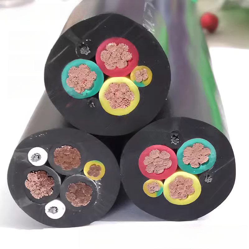
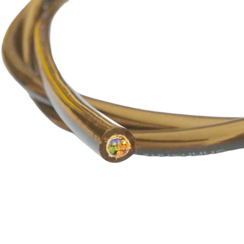
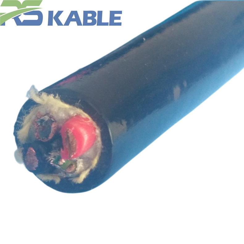
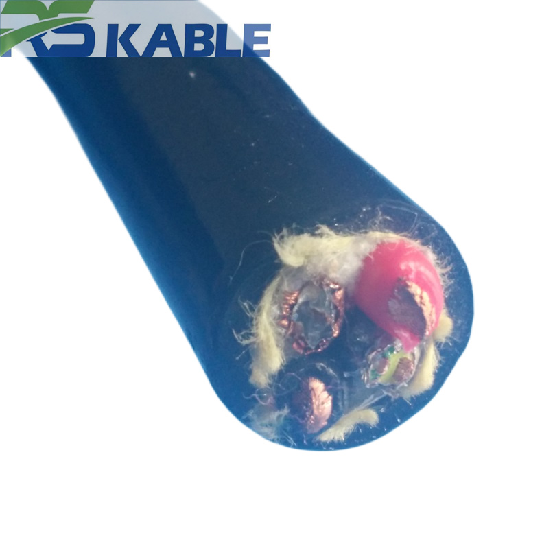
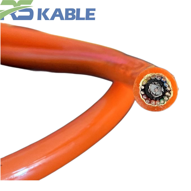
The coaxial power cable solves a wiring problem that every CCTV installer encounters: routing both the video signal and the camera power supply through a single cable run. Rousheng’s RST-CP series integrates a precision 75 Ω coaxial core with dedicated power conductors inside one outer jacket, eliminating a separate power cable run and reducing termination points by half.
What separates the RST-CP series from standard siamese cable is a four-layer isolation architecture that prevents the power conductors from coupling 50 Hz hum into the video signal path — a failure mode that affects every conventional combined cable design above 0.5 A power current. Measured isolation exceeds 74 dB at 50 Hz across all models.
This page covers model selection, technical specifications, voltage-drop calculations, replacement compatibility with existing siamese installations, and field-proven installation guidance for indoor, outdoor, direct-burial, and hazardous-area environments.
|
Isolation @ 50 Hz |
Video bandwidth |
Power rating |
Jacket options |
|
> 74 dB |
Up to 3 GHz |
300 / 500 V AC |
PVC · PUR · LSZH · DB |
|
Measured, not estimated |
HD-SDI / 4K-SDI capable |
12 V DC to 230 V AC |
Indoor to direct burial |
Five Questions That Determine Your Correct Coaxial Power Cable Model
How to select a coaxial power cable in under three minutes
The most common ordering errors arise from five decisions: video format, run length, power voltage, installation environment, and PTZ control. The step cards below route you to the correct model and conductor specification before reading the detailed specification.
|
Q1 |
Video format |
Analogue CCTV (AHD / TVI / CVI at 720p–5MP) → RG-59 equivalent (RST-CP-100/110, 750 MHz). HD-SDI 1080p/1080i → RG-6 equivalent (RST-CP-120/130, 1.5 GHz). HD-SDI 3G / 4K-SDI → HD-SDI model (RST-CP-200/210, 3.0 GHz). IP camera with PoE → use Cat5e + power combined cable instead; coaxial transmission is not compatible with IP Ethernet. |
|
Q2 |
Longest run |
Analogue CCTV: RG-59 suitable to 300 m (6 MHz signal bandwidth). HD-SDI 1080p: RG-6 to 80 m; HD-SDI model to 100 m. 4K-SDI: HD-SDI model to 50 m; beyond 50 m requires SDI reclocking amplifier at midpoint. Attenuation increases 0.4%/°C above 23 °C — recalculate for hot climates or unventilated ceiling spaces. |
|
Q3 |
Power voltage |
12 V DC: voltage drop is the binding constraint. At 1 A load, 0.75 mm² loses 2.47 V per 100 m. Camera needs ≥ 10.8 V, so the practical limit is 50 m. Use 1.5 mm² for 12 V runs beyond 30 m. 24 V DC: twice the drop budget; 0.75 mm² adequate to 100 m at 0.5 A. 230 V AC: use RST-CP-130/210 (300/500 V AC rated cores); verify local wiring regulations before routing mains alongside signal. |
|
Q4 |
Environment |
Indoor ceiling/trunking → PVC. Enclosed public space → LSZH mandatory. Outdoor UV exposure → PUR. Industrial floor/oil exposure → PUR oil-rated. Direct burial/ground trench → DB jacket ETO. Hazardous area Zone 2 → ATEX ETO (see dedicated section). |
|
Q5 |
PTZ control |
No PTZ → standard model. PTZ with RS-485 control → RST-CP-310 (RG-6 + RS-485 pair + 2 × 0.75 mm² power): one cable carries HD video, PTZ commands, and camera power. Continuous 360° pan → specify Class 5 flexible conductor at order (default Class 2 solid fatigues at pan axis within 6 months). |
Why Power Conductors Cause Hum in Combined Cable — and How RST-CP Prevents It
The 50 Hz shielding problem that standard combined cable cannot solve
A coaxial braid shield performs excellently as an RF return-path conductor above 1 MHz. At 50 Hz — the frequency at which mains power noise enters a video circuit — the physics changes completely.
The skin depth of tinned copper at 50 Hz is approximately 9.4 mm. Coaxial braid wire diameters are 0.1–0.15 mm. The 50 Hz magnetic field from a power conductor therefore penetrates the braid wire diameter approximately 60 times over — the braid is essentially transparent to power-frequency magnetic coupling. This is a physics boundary, not a manufacturing quality issue.
Any combined cable that relies on the coaxial braid to isolate the power conductors will introduce hum above a current threshold — typically 0.5 A with transformer-based power supplies. Standard siamese cable provides less than 40 dB isolation at 50 Hz for this reason.
RST-CP four-layer isolation: how the architecture eliminates hum
The RST-CP series uses two physical mechanisms in combination, providing additive isolation:
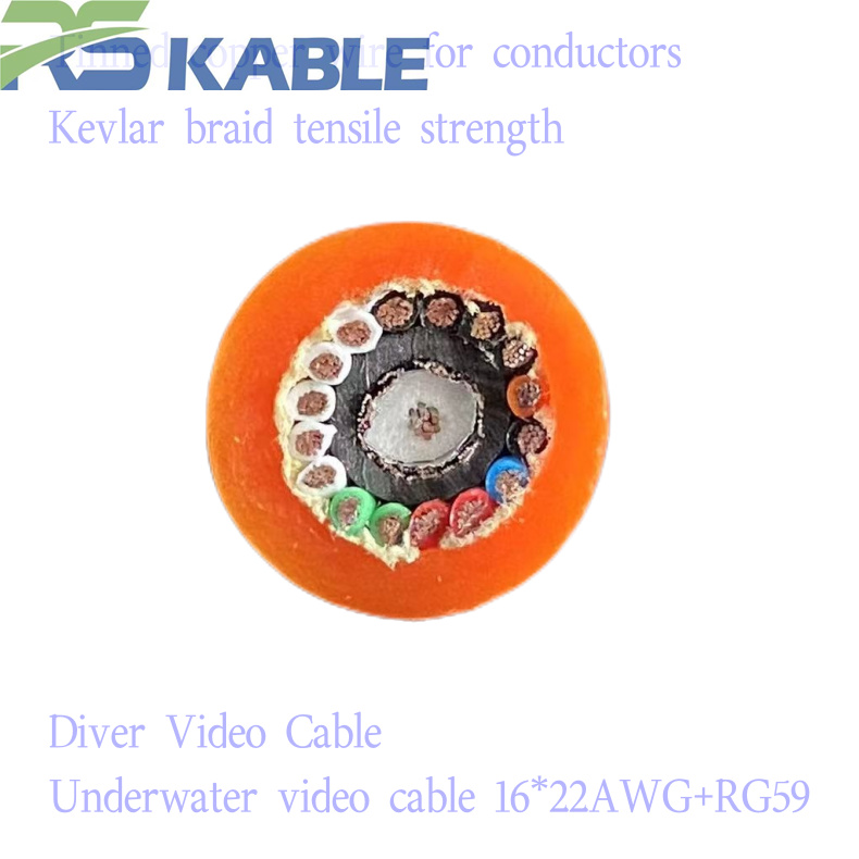
- Coaxial core (Layer 1): structurally identical to a standalone RG-59 or RG-6 — centre conductor, foam PE dielectric, AL/PET foil, tinned Cu braid. The coaxial return path is self-contained.
- PTFE separation tape (Layer 2): a defined slip plane between the coaxial core and the power bundle, also allowing coax extraction for field re-termination.
- Twisted power pair (Layer 3): power wires wound helically at 25–35 mm pitch. Differential magnetic field cancellation exceeds 40 dB at 50 Hz, independent of the coaxial shield.
- Outer foil shield (Layer 4): AL/PET foil over the combined bundle. Additive with the twisted-pair cancellation — total measured isolation exceeds 74 dB at 50 Hz.
|
MEASURED DATA |
Isolation on RST-CP-120, 100 m sample, 23 °C (network analyser, calibrated injection into power pair): 50 Hz: 74.2 dB · 100 Hz: 71.6 dB · 1 kHz: 68.3 dB · 10 kHz: 61.1 dB Degrades ~3 dB at 70 °C. Hum bars invisible on analogue CCTV at ≤ 3 A; below HD-SDI noise floor at ≤ 1.5 A. |
RST-CP Series Product Matrix
Standard coaxial power cable configurations
Nine standard configurations plus ETO. Attenuation values at 23 °C; derate 0.4%/°C above 23 °C. Bandwidth column shows the coaxial element’s −3 dB upper frequency.
|
Model |
Coax type |
Power cores |
Video BW |
Atten @100MHz |
OD (mm) |
Impedance |
Jacket / use |
|
RST-CP-100 |
RG-59 eq. |
2×0.5 mm² |
750 MHz |
≤7.5 dB |
8.2±0.3 |
75 Ω ±2 |
PVC · Indoor trunking |
|
RST-CP-110 |
RG-59 eq. |
2×0.75 mm² |
750 MHz |
≤7.5 dB |
9.0±0.3 |
75 Ω ±2 |
PUR · Outdoor / flex |
|
RST-CP-120 |
RG-6 eq. |
2×0.75 mm² |
1.5 GHz |
≤5.8 dB |
10.0±0.3 |
75 Ω ±2 |
PVC · Indoor |
|
RST-CP-130 |
RG-6 eq. |
2×1.0 mm² |
1.5 GHz |
≤5.8 dB |
10.8±0.3 |
75 Ω ±2 |
LSZH · Enclosed public |
|
RST-CP-200 |
HD-SDI (RG-6+) |
2×1.0 mm² |
3.0 GHz |
≤4.2 dB |
11.5±0.4 |
75 Ω ±1.5 |
PUR · HD broadcast/flex |
|
RST-CP-210 |
HD-SDI (RG-6+) |
2×1.5 mm² |
3.0 GHz |
≤4.2 dB |
12.5±0.4 |
75 Ω ±1.5 |
PUR · Outdoor UV-rated |
|
RST-CP-300 |
Dual RG-59 |
2×1.0 mm² |
750 MHz ×2 |
≤7.5 dB ea. |
13.0±0.4 |
75 Ω ±2 ea. |
PVC · Dual-output PTZ |
|
RST-CP-310 |
RG-6 + RS-485 |
2×0.75 mm² |
1.5 GHz |
≤5.8 dB |
11.0±0.4 |
75 Ω ±2 (coax) |
PVC · PTZ all-in-one |
|
RST-CP-C (ETO) |
Per spec |
Per spec |
Up to 3 GHz |
Per design |
8–18 mm |
75 Ω or 50 Ω |
PVC/PUR/LSZH/DB/ATEX |
Complete Technical Specification
Coaxial element — impedance and RF performance
|
Parameter |
Specification |
|
Impedance |
75 Ω ± 2 Ω standard; ± 1.5 Ω HD-SDI models; verified by TDR per IEC 61196-1 every production lot |
|
Centre conductor |
Bare copper (BC) standard; copper-clad steel (CCS) ETO for aerial/outdoor span applications |
|
Dielectric |
Physical foam PE; velocity factor ≥ 82%; dielectric constant ≤ 1.50; foam cell diameter ≤ 0.3 mm for impedance consistency over 300 m runs |
|
Inner shield |
AL/PET foil 100% coverage + tinned Cu braid ≥ 95% optical; return loss ≥ 26 dB at 5–1000 MHz; ≥ 23 dB at 5–3000 MHz (HD-SDI) |
|
Attenuation per 100 m |
RG-59: 7.5 dB @ 100 MHz · 17.2 dB @ 500 MHz | RG-6: 5.8 dB @ 100 MHz · 12.4 dB @ 500 MHz | HD-SDI: 4.2 dB @ 100 MHz · 18.6 dB @ 1.5 GHz |
|
Velocity factor |
≥ 82%; 1 m of cable ≈ 4.1 ns signal delay; relevant in synchronised multi-camera rigs where cable lengths must match ± 0.5 m |
|
Power-to-coax isolation |
74.2 dB @ 50 Hz · 71.6 dB @ 100 Hz · 68.3 dB @ 1 kHz · 61.1 dB @ 10 kHz (measured); ~3 dB degradation at 70 °C |
|
Foam dielectric pull limit |
Max tension: 100 N (≤10 mm OD); 150 N (>10 mm OD). Excess tension permanently compresses foam, creating ±3–8 Ω impedance deviation. On analogue CCTV: ≤3 Ω deviation invisible. On HD-SDI: >5 Ω causes reflected power >−20 dB, producing intermittent bit errors on runs >80 m |
Power conductors — ratings and voltage drop
|
Parameter |
Specification |
|
Conductor class |
IEC 60228 Class 2 (solid/7-wire) standard for static installations; Class 5 fine-stranded for PTZ pan axis and flex applications — specify ‘Class 5’ at order |
|
Insulation |
PVC 70 °C rated standard; XLPE 90 °C for outdoor/high-temp; colour red/black or brown/blue per IEC 60446 |
|
Rated voltage |
300/500 V AC standard; 450/750 V AC ETO; supports 12/24 V DC and 110/230 V AC |
|
Current capacity (free air, 30 °C) |
0.5 mm²: 3 A · 0.75 mm²: 6 A · 1.0 mm²: 10 A · 1.5 mm²: 13 A · 2.5 mm²: 18 A |
|
Voltage drop formula |
V_drop = 2 × L(m) × I(A) × R(Ω/m). Resistance per metre: 0.5 mm²=0.0393 · 0.75 mm²=0.0247 · 1.0 mm²=0.0193 · 1.5 mm²=0.0133 · 2.5 mm²=0.00754. Multiply R by 1.02 per 5 °C above 20 °C for hot environments. |
|
Twist configuration |
Power pair wound helically at 25–35 mm pitch; >40 dB field cancellation at 50 Hz; additive with outer foil shield for total >74 dB isolation |
Outer jacket ratings by installation environment
|
Jacket |
Temp range |
Key resistance |
Not suitable for |
Install context |
|
PVC |
−20 °C to +70 °C |
Flame retardant IEC 60332-1 |
Direct UV >6 months; oil immersion |
Indoor trunking, conduit, ceiling void |
|
PUR |
−40 °C to +90 °C |
UV-stabilised 10+ yr outdoor; oil/coolant resistant |
Sustained ketone/aromatic solvents |
Outdoor, industrial floor, crane, gantry |
|
LSZH |
−15 °C to +70 °C |
IEC 60332-3-22; smoke density ≥60% per IEC 61034-2 |
Outdoor UV; oil; bare mechanical impact |
Enclosed public: malls, tunnels, transport |
|
DB (ETO) |
−20 °C to +70 °C |
Gel-fill + HDPE outer; IP68 eq.; depth to 1.0 m |
Vertical runs >10 m without cable support |
Trench direct burial, perimeter runs |
|
ATEX (ETO) |
−20 °C to +70 °C |
Surface resistance <10⁹ Ω (IEC 60093); Zone 2 IIC rated |
Zone 0 / Zone 1 — different standard required |
Petrochemical, paint spray, solvent-area CCTV |
Maximum Run Length Reference: Voltage Drop and Coaxial Attenuation
Coaxial power cable run limits for 12 V DC systems
At 12 V DC, voltage drop is almost always the binding constraint — not coaxial attenuation. The table below gives maximum run lengths for common camera configurations. Red rows indicate voltage drop is limiting; green rows indicate the camera receives ≥ 10.8 V at the stated distance.
|
Camera current |
Conductor |
V drop @ stated run |
Max run (V drop limit) |
Coax attenuation limit |
|
0.3 A |
0.75 mm² |
1.49 V @ 100 m |
83 m (camera receives 10.51 V) |
Not limiting — RG-59 analogue limit 300 m |
|
0.3 A |
1.5 mm² |
0.80 V @ 100 m |
154 m ✓ (≥10.8 V maintained) |
Not limiting |
|
0.5 A (typical AHD) |
0.75 mm² |
2.47 V @ 100 m |
50 m (binding) |
Not limiting |
|
0.5 A |
1.5 mm² |
1.33 V @ 100 m |
92 m ✓ |
Not limiting |
|
1.0 A (IR illuminator) |
1.5 mm² |
2.66 V @ 100 m |
46 m only — switch to 24 V supply |
Not limiting — 24 V solves this |
Coaxial power cable run limits for 24 V DC and HD-SDI systems
At 24 V, the drop budget doubles. For HD-SDI, coaxial attenuation becomes the binding constraint at longer runs.
|
Configuration |
Model |
V drop @ max run |
Max run (V drop) |
Max run (coax attenuation) |
|
24 V / 0.5 A AHD |
RST-CP-110 |
1.24 V @ 100 m |
200 m ✓ |
300 m (RG-59) — V drop is binding |
|
24 V / 0.5 A HD-SDI |
RST-CP-200 |
1.24 V @ 100 m |
200 m ✓ |
100 m (1.485 GHz, ≤20 dB) — coax binding |
|
24 V / 0.5 A 4K-SDI |
RST-CP-200 |
1.24 V @ 100 m |
200 m ✓ |
50 m (11.88 GHz) — add SDI reclocking amplifier |
|
230 V AC / 0.2 A |
RST-CP-130 |
< 1 V across any CCTV run |
Not a constraint |
300 m analogue / 80 m HD-SDI — check wiring regs for mains in signal cable |
Replacing Siamese Cable with Coaxial Power Cable: Compatibility Guide
Outer diameter comparison and BNC connector compatibility
RST-CP cables are 1–3 mm larger in OD than equivalent siamese cables due to the round outer jacket replacing the figure-8 geometry. This affects conduit fill but not BNC connector installation — here is why.
BNC crimp and compression connectors are sized to the coaxial core OD, not the combined cable OD. When installing a BNC on RST-CP cable, the outer jacket is stripped back 40–50 mm to expose the coaxial core, which is then terminated exactly as a standalone RG-59 or RG-6 cable. The RG-59 equivalent coaxial core in all RST-CP models is 6.2 mm OD — compatible with standard RG-59 BNC crimp dies. The RG-6 equivalent core is 6.8 mm OD — compatible with standard RG-6 compression connectors.
|
Existing cable |
Siamese OD (typical) |
RST-CP replacement OD |
Connector action required |
|
RG-59 siamese |
6.2–7.5 mm coax section |
RST-CP-100: 8.2 mm RST-CP-110: 9.0 mm |
Strip outer jacket 50 mm; terminate coax core (6.2 mm OD) with existing RG-59 BNC dies. No new BNC hardware needed. Power terminals unchanged. |
|
RG-6 siamese |
7.0–8.2 mm coax section |
RST-CP-120: 10.0 mm RST-CP-130: 10.8 mm |
Strip outer jacket 50 mm; terminate coax core (6.8 mm OD) with existing RG-6 compression or crimp dies. Outer jacket OD is irrelevant to BNC installation. |
|
Siamese with 2 mm² power |
Varies |
Order RST-CP-C ETO with 2.0 mm² power cores |
RST-CP standard range reaches 2.5 mm². Screw terminal and ferrule sizes are conductor-cross-section dependent — BNC hardware unchanged. |
Conduit sizing and ground loop behaviour after replacement
Because RST-CP has a larger OD than equivalent siamese cable, check conduit fill before ordering. A round cross-section fills a circular conduit more efficiently than a figure-8 cross-section. Practical rule: RST-CP will fit the same conduit as the equivalent siamese grade if the existing conduit fill ratio was ≤ 40%. If the conduit is near capacity, measure the internal diameter and confirm against RST-CP OD plus 20% clearance.
Ground loop behaviour: RST-CP’s improved isolation reduces hum from magnetic coupling, but pre-existing ground loops between camera chassis and recorder chassis through the power conductors persist after replacement — they are a system topology issue. If the siamese installation had hum, inspect the power supply grounding and camera chassis bonding before assuming a cable change alone will resolve it.
Extended Environment Specifications
Direct burial coaxial power cable — RST-CP-C DB variant
The DB variant uses a gel-filled inner layer and a high-density polyethylene outer jacket for continuous soil contact without conduit.
|
Parameter |
Specification |
|
Burial depth |
Minimum 500 mm (open ground) · 750 mm (paved surfaces) · 1,000 mm (roadways) |
|
Moisture protection |
IP68 equivalent (2 m, 24 h per IEC 60529); gel filling prevents water migration along cable core even if outer jacket is nicked |
|
Soil pH compatibility |
pH 4–11; suitable for clay, loam, sand, chalk; not suitable for contaminated land with sustained organic solvent or fuel concentration above 2% v/v |
|
Temperature range |
−20 °C to +70 °C; do not install below −10 °C ground temperature (gel becomes viscous) |
|
Pulling tension |
Maximum 150 N for ≤12 mm OD; foam dielectric pull limit applies equally to DB variants |
Hazardous area Zone 2 coaxial power cable — RST-CP-C ATEX variant
Zone 2 covers areas where explosive gas is not present in normal operation but may occur abnormally — petrochemical boundary areas, paint spray booths, solvent storage perimeters.
|
Parameter |
Specification |
|
Anti-static jacket |
Surface resistance <10⁹ Ω per IEC 60093; prevents electrostatic charge accumulation — the relevant ignition mechanism in Zone 2 |
|
Gas group |
IIC (hydrogen, acetylene — covers all lower groups IIB and IIA); T4 temperature class (max surface 135 °C) standard; T5 (100 °C) available ETO |
|
Zone 2 documentation |
Ex marking, surface resistance test report per IEC 60093, ATEX material declaration — provided per production lot for inclusion in area classification documentation |
|
Cable gland |
Ex cable gland (Zone 2 IIC rated) required — installer scope; Rousheng confirms cable OD for gland selection at order |
|
Zone 0 / Zone 1 |
This variant is Zone 2 only. Zone 0/1 requires Ex i or Ex d circuits — outside the RST-CP product range |
Field Diagnostic Reference: Five Common Installation Faults
Diagnosing coaxial power cable video degradation on site
These five faults account for the majority of post-installation technical support queries on coaxial power cable installations. Each row includes the quantified threshold at which the fault becomes visible — the most actionable data for a site engineer.
|
Symptom |
Root cause |
Detection threshold |
Correction and quantified guidance |
|
Hum bars at 50 Hz |
Parallel (untwisted) power pair — <40 dB isolation at 50 Hz |
Visible at ≥0.5 A load |
Measure isolation between power pair and coax at 50 Hz with LCR meter. RST-CP provides >74 dB — hum invisible below 3 A. If replacement cable does not eliminate hum: fault is a ground loop (camera chassis to recorder chassis), not cable quality. Float camera chassis with isolation gland at mount. |
|
TDR impedance bump at fixed position |
Foam dielectric compressed during pull — exceeded 100 N / 150 N limit |
TDR shows reflection when deviation ≥ 2 Ω |
Foam deformation creates ±3–8 Ω deviation. Analogue CCTV: not visible up to ±3 Ω. HD-SDI: intermittent errors when deviation >5 Ω on runs >80 m — reflected power exceeds −20 dB. Prevention: pull sock on outer jacket; never pull on coax core; calculate tension before pulling; use lubricant in conduit for runs >20 m. |
|
HD-SDI loss — temperature dependent |
Run calculated at 23 °C; installed at 50–70 °C ceiling or conduit |
Loss when corrected attenuation exceeds 20 dB |
Derate attenuation by 0.4%/°C above 23 °C. Example: RST-CP-200, 100 m, 60 °C: 4.2 dB/100m × 1.148 = 4.82 dB/100m × 100 = 18.2 dB. Passes. At 70 °C: 4.2 × 1.188 × 100 = 19.9 dB. Borderline — add SDI reclocking DA at recorder input. |
|
PTZ pan cable fails at connector in <6 months |
Class 2 solid conductor on continuous pan axis |
Work-hardening begins below 500,000 bend cycles |
Class 2 flex life: 200,000–500,000 cycles at 10× OD. At 50 pans/hour × 18 hr/day: failure within one year. Order with ‘Class 5 flexible conductor’. Allow 300 mm service loop at camera mount — verify loop geometry does not reach 6× OD minimum at pan extremes. |
|
Colour cast shifts over weeks |
Power conductor resistance increasing — corrosion or loose termination raising voltage drop |
Camera ISP errors when supply drops >1 V below nominal |
Measure conductor resistance (Kelvin 4-wire). 100 m of 0.75 mm² = 3.3 Ω nominal; increase >0.5 Ω indicates fault. Re-terminate all junctions. In marine/humid environments specify tinned conductor ETO — bare copper oxidation adds 0.1–0.5 Ω per poorly sealed joint over 12 months. |
Frequently Asked Questions
What makes RST-CP different from standard siamese coaxial power cable?
Standard siamese cable runs power wires parallel to the coaxial braid — providing less than 40 dB isolation at 50 Hz. The RST-CP series uses a helically twisted power pair (>40 dB cancellation from field geometry) plus an outer foil shield (additive), achieving >74 dB measured isolation. The difference is invisible at low current DC loads. It becomes visible as hum bars above 0.5 A with transformer-based supplies, or on any 230 V AC powered installation. The RST-CP architecture eliminates this fault mode entirely.
Can I use a coaxial power cable for IP cameras?
Not directly. IP cameras encode video as Ethernet packets requiring 100BASE-TX or 1000BASE-T balanced twisted-pair transmission. Using coaxial cable for IP video requires a video balun at each end, adding cost and a conversion step. For IP cameras, use Cat5e or Cat6 plus power conductors — not a coaxial combined cable. Rousheng’s RST-CP-E series covers Cat5e/Cat6 + power configurations for IP CCTV applications.
What happens if PVC-jacketed coaxial power cable is installed outdoors in direct sunlight?
PVC UV stabilisers protect the jacket for 6–18 months in direct Southern European or Middle Eastern sunlight. Beyond this, the jacket chalks, micro-cracks, and eventually fractures at bend points. Moisture enters, migrates to the foam dielectric, and shifts the impedance locally. Specify PUR jacket for any outdoor direct-exposure installation — PUR is UV-stabilised for over 10 years outdoor. The cost difference between PVC and PUR is approximately 15–25%; replacement labour when PVC fails outdoors always costs more.
Is this cable suitable for PTZ cameras with continuous 360° pan rotation?
Yes, with Class 5 flexible conductor specified at order. The default Class 2 conductor has a flex life of 200,000–500,000 cycles at 10× OD — insufficient for continuous PTZ cycling. Class 5 uses fine-stranded copper (≥16 wires for 0.75 mm²) rated for continuous rotation. The coaxial element specification is unchanged between Class 2 and Class 5. Install with a 300 mm service loop at the camera mount to prevent the cable reaching the 6× OD minimum bend radius limit at pan extremes.
How do I verify installed coaxial power cable passes HD-SDI requirements?
Use a TDR with 75 Ω reference impedance and a ≤2 ns rise-time test pulse. A correctly installed cable shows flat 75 Ω ±2 Ω from injection to end reflection. For HD-SDI qualification, also measure return loss with a network analyser — the specification requires ≥23 dB at 5–3000 MHz. A cable meeting TDR impedance will also meet return loss unless minimum bend radius (6× OD) was violated during installation.
Request Samples, Test Reports, or a Quotation
What to include for a complete first-reply response
Rousheng provides cable samples with attenuation sweep, TDR impedance trace, and power-to-coax isolation measurement at 50 Hz, 100 Hz, 1 kHz, and 10 kHz before order placement. Share the following for the most complete single-reply response:
- Video format: AHD/TVI/CVI (resolution), HD-SDI, 4K-SDI, or IP (for Cat + power cable)
- Maximum single run length (longest camera cable run in the installation)
- Camera power supply voltage and maximum current draw per camera
- Installation environment: indoor, outdoor, industrial, direct burial, or hazardous area
- PTZ camera: yes/no; rotation type (limited-angle or continuous 360°) if yes
- Jacket compound: PVC / PUR / LSZH / DB / ATEX — or describe the environment
- Conductor class: static installation (Class 2) or PTZ/flexible (Class 5 specify)
- Quantity: metres on reel, or cut lengths with connector type if pre-terminated
- Replacement job: existing cable OD and connector type for compatibility confirmation
|
CONTACT |
Email: Jerry@rstlkable.com WhatsApp / Phone: +86 134 8219 7396 Address: No. 2591 Fengzhe Road, Fengxian District, Shanghai, China Sample requests: state model number and installation description. |