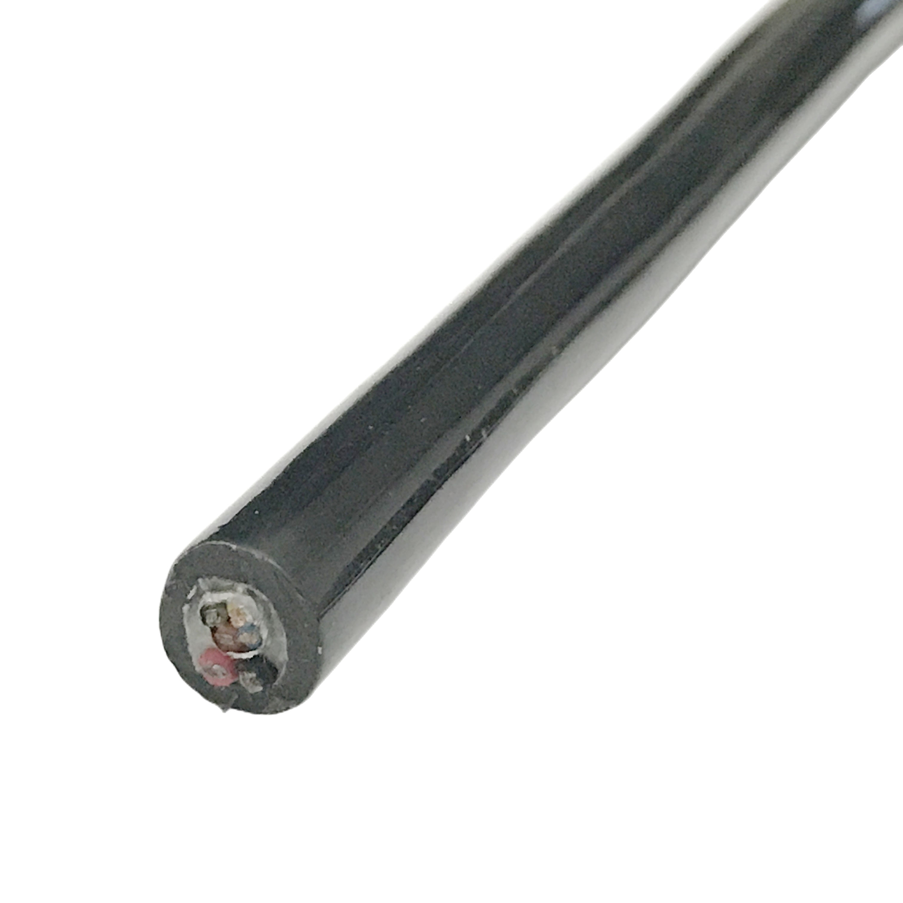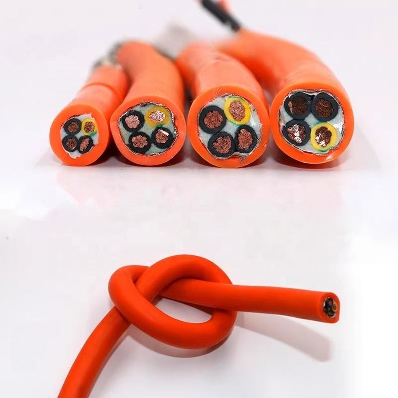



AS-i Bus Cable 2×1.5mm² | Industrial Fieldbus Cable for Automation Systems
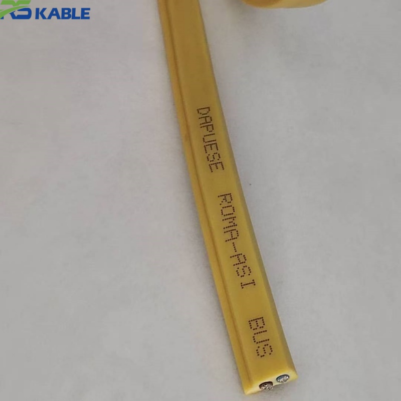
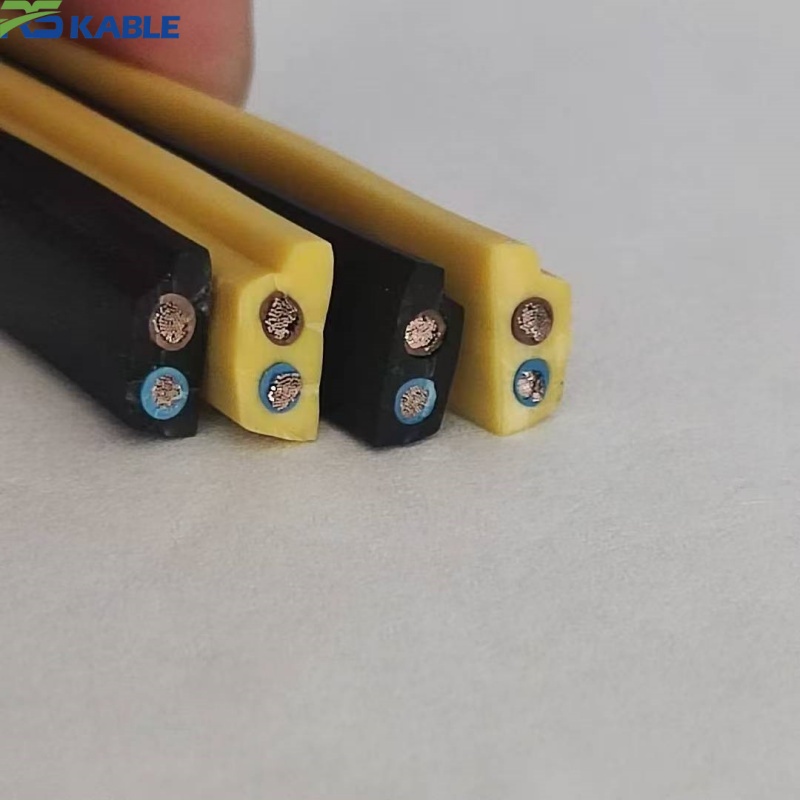
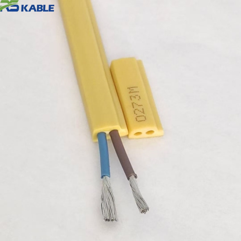
AS-i Bus Cable 2×1.5mm² is an industrial fieldbus cable built for AS-Interface sensor and actuator networks with multi-point piercing-connector taps. Its trapezoidal, keyed profile ensures polarity-evident, reliable connector seating at every tap point, with a standard PVC jacket for ambient installations or a silicone high-temperature variant for runs routed near heat sources.
Key Benefits:
✅ Trapezoidal keyed profile prevents reversed polarity at tap connections
✅ Piercing-connector compatible conductor construction for mid-run taps without cutting
✅ Standard AS-i yellow jacket for easy visual identification during maintenance
✅ Optional silicone high-temp variant for heat-exposed cable routing segments
AS-i Bus Cable 2×1.5mm² | Industrial Fieldbus Cable for Automation Systems
Technical Reference — AS-Interface (AS-i) Bus Cable Specification
Five things people get wrong about AS-i cabling before they’ve installed it
AS-i (Actuator Sensor Interface) is a simpler bus protocol than most industrial fieldbuses, but that simplicity is exactly why installation mistakes happen — people apply assumptions from other fieldbus cabling (Profibus, DeviceNet) that don’t actually hold for AS-i. Working through the misconceptions is a more useful starting point than a spec list, because most of the questions that come up during specification trace back to one of these five points.
Misconception 1: “AS-i cable needs to be shielded like other fieldbus cable.” Not typically. AS-i’s signal encoding (a current-modulated signal riding on the same two conductors as the 24V-class supply) was specifically designed to tolerate standard industrial EMI without requiring a shield in most installations. Unshielded 2×1.5mm² is the standard construction — adding shielding isn’t wrong, but it’s rarely the fix people expect it to be if noise problems appear; the more common cause is topology or cable length, addressed below.
Misconception 2: “The network has to be wired in a line/daisy-chain topology.” This is true for most other fieldbuses, but not for AS-i. One of AS-i’s defining features is that it tolerates line, tree, star, or ring topology — devices don’t need to be wired in sequence. This flexibility is a genuine advantage, but it also means topology isn’t the first thing to check when troubleshooting; total cable length and the number of devices are more often the actual constraint.
Misconception 3: “Any 2-core cable of the right gauge will work.” The gauge (2×1.5mm²) matters, but so does the specific conductor construction. AS-i cable is typically unshielded, often with a distinctive profile (many installations use the standard yellow AS-i cable specifically so it’s visually distinguishable from other cabling during maintenance) and a construction suited to the piercing/insulation-displacement connectors commonly used for tapping into the network without cutting the cable. A generic 2-core cable not designed for IDC-style tapping can cause connection reliability issues even if the gauge is correct.
Misconception 4: “AS-i doesn’t have a practical length limit since it’s not a fixed bus topology.” It does — the commonly cited limit is 100 meters of total cable length per segment without a repeater/extender, regardless of topology shape. This is a voltage-drop and signal-timing constraint, not a topology constraint, which is why changing topology doesn’t extend it — only a repeater does.
Misconception 5: “Since AS-i carries both power and data on the same two wires, any power cable of the right voltage will do as a substitute in a pinch.” This is one of the more common shortcuts that causes intermittent problems. AS-i’s data signal is a specific current-modulated waveform superimposed on the DC supply; a generic power cable’s electrical characteristics (particularly capacitance and any unexpected added modules along the run) can distort that signal even when the gauge and voltage rating look correct on paper.
What this cable actually is
| Element | Specification |
|---|---|
| Configuration | 2 cores × 1.5 mm² |
| Conductor material | Tinned or bare copper, per project requirement |
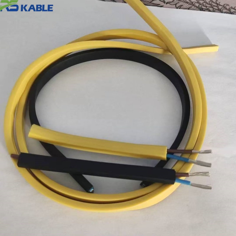
| Cable profile | Standard round or AS-i-typical trapezoidal/flat profile (both available) |
| Jacket color | AS-i standard yellow (custom colors available) |
| Voltage rating | Rated for AS-i’s 29.5–31.6V DC operating range |
| Temperature rating | -20°C to +80°C standard (high-temperature silicone-jacketed variant available to +200°C for near-motor or oven-adjacent routing) |
| Shielding | Unshielded standard construction |
| Connector compatibility | Suitable for piercing/IDC-style tap connectors without cutting the main run |
| Max segment length (typical) | 100 meters without repeater, per standard AS-i network design guidance |
Note on the high-temperature variant: most AS-i installations don’t need heat resistance beyond standard PVC-jacketed cable, since the bus typically runs to sensors and actuators rather than through hot zones directly. The silicone-jacketed high-temperature version exists specifically for installations where the AS-i run is routed near ovens, motor housings, or other heat sources along its path — not as a general upgrade.
Where this cable fits
Standard AS-i cable (PVC jacket) is correct when:
- the network connects distributed sensors/actuators in a moderate-temperature industrial environment
- installation uses standard piercing-tap connectors along the run
- total segment length stays within the 100-meter guideline
The high-temperature silicone variant is worth the added cost when:
- part of the AS-i run is physically routed near a heat source (oven wall, motor housing) even if the connected devices themselves aren’t in that zone
- ambient temperature along the cable path — not just at the device end — regularly exceeds standard PVC’s practical service range
This is not the right product when:
- the application actually needs a different fieldbus protocol (Profibus, DeviceNet, IO-Link) — AS-i cable’s construction is specific to AS-i’s signal encoding and isn’t a substitute for those cable specs even at a similar gauge
- the segment requires more than 100 meters without a planned repeater — extending cable length without addressing the underlying voltage/timing limit will produce intermittent communication faults regardless of cable quality
A troubleshooting pattern worth naming
A commonly seen pattern, described generally rather than as a specific verified case: an AS-i network with intermittent device dropouts, occurring more frequently as more devices were added to the segment over time, traced back not to a faulty cable or connector but to cumulative segment length creeping past the 100-meter guideline as the network was extended device by device without anyone tracking total run length. Because AS-i tolerates flexible topology, it’s easy to keep adding branches without a clear sense of cumulative length — unlike a line topology where added length is visually obvious. Tracking total segment length as devices are added, rather than only checking it when problems appear, is the more reliable long-term practice.
Frequently Asked Questions
Do we need shielded cable for our AS-i network? Typically no — AS-i’s signal encoding is designed to tolerate standard industrial EMI without shielding in most installations. If noise problems appear, checking segment length and topology is usually more productive than adding shielding.
Can we wire our AS-i network in a star topology instead of a line? Yes — this is one of AS-i’s defining advantages over most other fieldbuses. Total cable length across the segment matters more than the topology shape.
What happens if our segment needs to exceed 100 meters? A repeater/extender is needed to maintain reliable communication beyond the standard segment length guideline; simply using a lower-gauge or different cable will not extend this limit, since it’s a voltage/timing constraint rather than a cable-quality constraint.
Does the cable need to be the standard yellow color? Not electrically — color doesn’t affect signal performance. Yellow is a widely used convention specifically so AS-i cable is visually distinguishable from other wiring during maintenance and troubleshooting, which has practical value even though it isn’t a technical requirement.
When does the high-temperature silicone version make sense over standard PVC? When the cable’s physical routing path passes near a heat source (oven, motor housing) even if the connected sensors/actuators themselves are in a cooler zone — the relevant temperature is along the cable run, not just at the device end.
Specification Checklist for Quotation
- Total planned segment length (and expected future expansion)
- Number of devices and topology shape (line/tree/star)
- Whether any portion of the cable run passes near a heat source
- Connector/tapping method in use (piercing/IDC vs standard terminal)
- Cable profile preference (round vs flat/trapezoidal)
[Request a Quotation] · [Ask an Engineer Before You Spec It] · [Download Technical Datasheet]