Low vs High Voltage ROV Cable: Selection Guide
Choosing the right ROV cable voltage architecture is one of the most consequential decisions in any ROV system specification. Get it wrong, and the vehicle either cannot deliver full thrust at depth, or the system is over-engineered and overpriced for what it actually needs to do.
This guide draws a clear line between low voltage and high voltage tether designs. It explains the physics behind each approach and gives you a practical decision framework. Whether you are specifying a new system or diagnosing an existing one, the answer comes from calculation — not convention.
What this article covers:
- How low voltage and high voltage ROV cable differ in construction and physics
- A side-by-side comparison across eight real selection criteria
- Four deployment scenarios with the decision logic for each
- A five-question framework to select the right architecture
- Six FAQ answers covering the most common specifier questions
1. Defining the Terms
In ROV tether design, ROV cable voltage refers to the transmission voltage on the power conductors — not the operating voltage of onboard components. A high voltage tether can supply 300 VDC over the cable while every thruster and camera runs on 24 VDC after onboard conversion.
The IEC 60038 standard defines low voltage as up to 1,000 VAC or 1,500 VDC. In ROV practice, the working definitions are narrower:
|
Category |
Voltage range |
IEC reference |
Typical application |
|
LV tether (standard) |
12–48 VDC |
IEC 60038 Band I |
Shallow, light-load ROVs |
|
Mid-range tether |
48–150 VDC |
IEC 62368-1 boundary |
Medium depth, moderate load |
|
HV tether |
150–600 VDC |
Hazardous voltage class |
Work-class, deep-water ops |
|
EHV tether |
> 600 VDC |
IEC 60840 |
Deep science platforms |
Table 1. Voltage classification for ROV tethers. IEC 62368-1 sets the hazardous voltage boundary at 60 VDC — above this, mandatory safety controls apply.
Key distinction: Transmission voltage ≠ component voltage. HV tethers use onboard DC-DC converters to step down to component-level voltages. This separation is what makes long-range, high-power operation possible.
2. The Physics: Why Voltage Class Matters
The core equation
Voltage drop in any tether follows a simple relationship:
Formula: V_drop = I × R where R = (2 × L × ρ) / A ρ = copper resistivity (0.0171 Ω·mm²/m) · L = one-way tether length (m) · A = conductor area (mm²)
For a fixed power load, raising the transmission voltage reduces the required current (I = P / V). Less current means less drop — and less heat in the cable.
Numbers at a real operating point
The table below compares four transmission voltages on a 400 m tether with 4 mm² conductors, delivering 1,000 W to the vehicle. The results explain why ROV cable voltage selection is not a minor detail.
|
Transmission V |
Current |
Tether drop |
Drop % |
Cable loss |
|
48 VDC |
20.8 A |
29.2 V |
61% |
607 W |
|
120 VDC |
8.3 A |
11.7 V |
10% |
97 W |
|
300 VDC |
3.3 A |
4.7 V |
1.6% |
15 W |
|
600 VDC |
1.7 A |
2.3 V |
0.4% |
4 W |
Table 2. Voltage drop comparison — 400 m tether, 4 mm² copper conductors, 1,000 W load, 20°C. At 48 VDC the vehicle receives less than 19 V — below the operating threshold of virtually every ROV drive system.
At 48 VDC, the system is losing 61% of its transmitted power as heat in the cable. The vehicle cannot function. This is not a marginal case — it is the documented result of specifying LV tether at HV-appropriate depth and load.
Why temperature makes it worse
Copper resistivity rises 0.39% per °C above 20°C. A tether drum running at 55°C under load has 14% more resistance than the datasheet value. On a design that already has thin voltage margin, this is enough to push the system below minimum operating voltage. Always apply a temperature correction when building your voltage budget.
3. Eight-Criterion Comparison
Neither architecture wins across all criteria. The following table shows where each one leads and where it falls short.
|
Criterion |
Low voltage tether (≤48 VDC) |
High voltage tether (≥150 VDC) |
|
Max practical depth |
~150 m (4 mm² conductors) |
1,000 m+ without conductor penalty |
|
Power budget ceiling |
~300 W at 100 m; ~100 W at 300 m |
5 kW+ viable at any depth |
|
Conductor size |
Grows rapidly with depth and load |
Thin conductors remain viable at depth |
|
Tether weight |
Heavy at medium depth |
Lighter; better vehicle handling |
|
Onboard conversion |
Direct supply — no converter |
DC-DC converter required |
|
System complexity |
Simple; fewer failure modes |
Higher; converter adds failure point |
|
Personnel safety |
Safe to handle without special controls |
Hazardous voltage — IEC 62368-1 controls required |
|
Total cost |
Lower cable and system cost |
Higher upfront (converter, HV insulation) |
Table 3. Eight-criterion comparison. LV wins on simplicity and cost inside its operating envelope. HV is a necessity — not a luxury — when depth or load exceeds LV limits.
4. Four Real Deployment Scenarios
Scenario A — Shallow inspection (LV, 12–48 VDC)
A civil contractor running dam face and harbor floor surveys operates at depths under 60 m. Vehicle power budget: under 200 W. Tether length: 60–100 m.
A 48 VDC tether with 1.5–2.5 mm² conductors delivers adequate power here. Drop stays below 8%. The cable is light enough to handle without a deployment drum. No converter is needed. Safety requirements are minimal.
One of our clients operates eight inspection vehicles on 100 m LV tethers across Southeast Asia. Switching to HV would add USD 4,500 per vehicle in converter and safety costs with zero operational benefit. LV is correct for this use case.
Scenario B — Offshore wind inspection (mid-range, 72–120 VDC)
Inspection ROVs working wind turbine foundations at 30–80 m depth often carry HD lighting arrays and multi-axis thruster systems. Total power budget: 600–900 W.
At 48 VDC, 4–6 mm² conductors are needed. The resulting cable becomes heavy and hard to handle. At 72–120 VDC, conductor sizing drops roughly in half. This mid-range zone sits below the IEC 62368-1 hazardous voltage threshold — simplifying safety compliance while solving the conductor weight problem.
This architecture is often overlooked. It is frequently the optimal choice for 50–150 m, medium-load applications.
Scenario C — Oil and gas work-class ROV (HV, 300–600 VDC)
A work-class vehicle inspecting subsea wellheads at 200–800 m depth carries a 3–5 kW power budget for thrusters, manipulators, and sonar.
At 500 m depth with 3 kW load, a 48 VDC system would need conductors exceeding 16 mm² to hold acceptable voltage drop. The resulting tether would be unmanageable on a standard deployment drum.
The same system at 300 VDC uses 2.5 mm² conductors with under 3% drop. The cost of the HV architecture is not a premium — it is the minimum bill of materials for a system that can function at all at this depth.
Scenario D — Deep-sea science platform (HV, 600–3,000 VDC)
Scientific ROVs operating at 2,000–6,000 m have no viable alternative to high voltage transmission. Tether length alone creates resistance values that make sub-600 V operation impossible regardless of conductor size.
One program we reviewed was scoped at 600 VDC for 3,500 m operations. Load analysis revealed a peak demand of 8.2 kW. The final design used 1,200 VDC with dual-stage onboard conversion. This decision was made at specification — not at sea trial. That timing difference is significant.
Field note: In all four scenarios, the voltage architecture was determined by physics and load, not by preference. Run the numbers first. The architecture follows from the calculation.
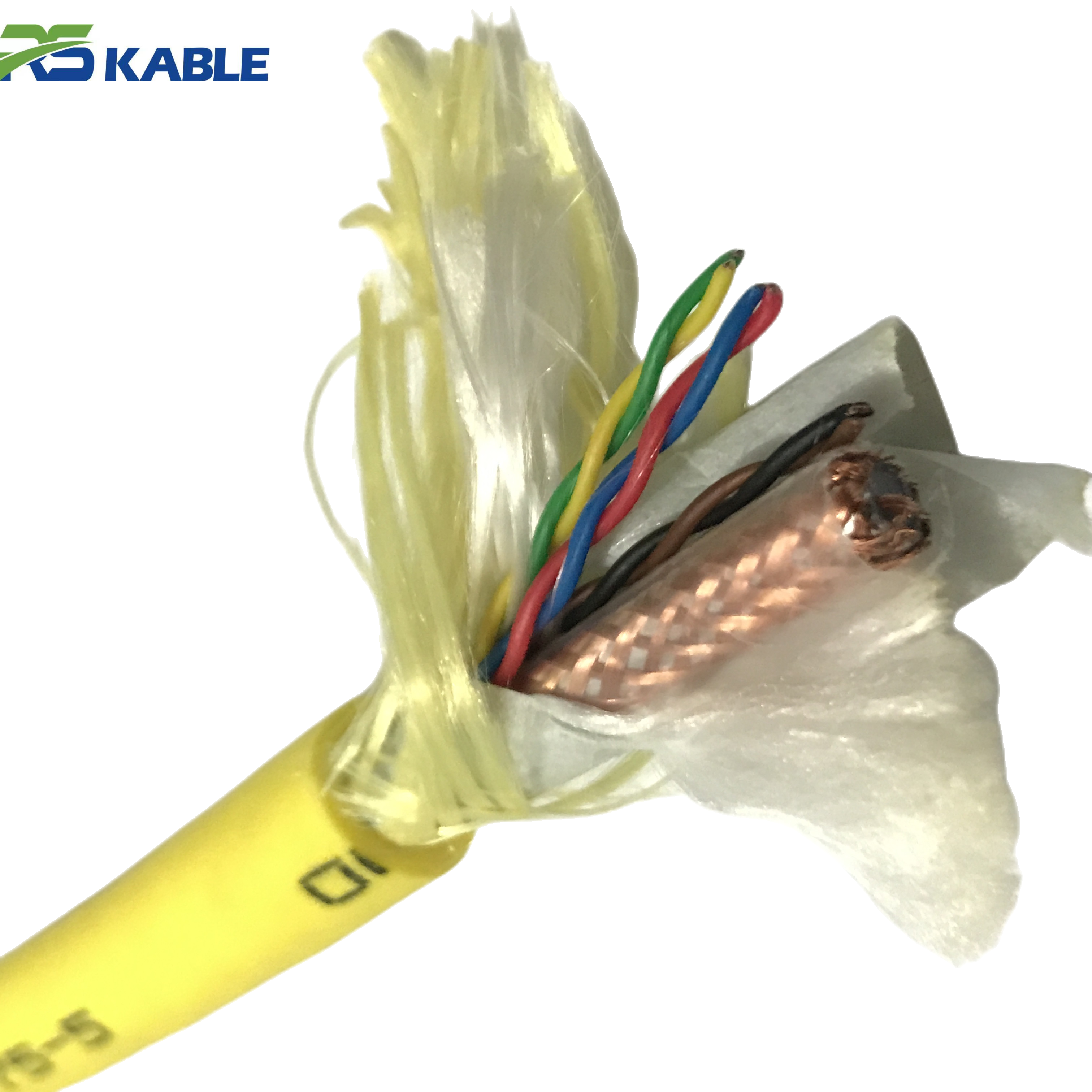
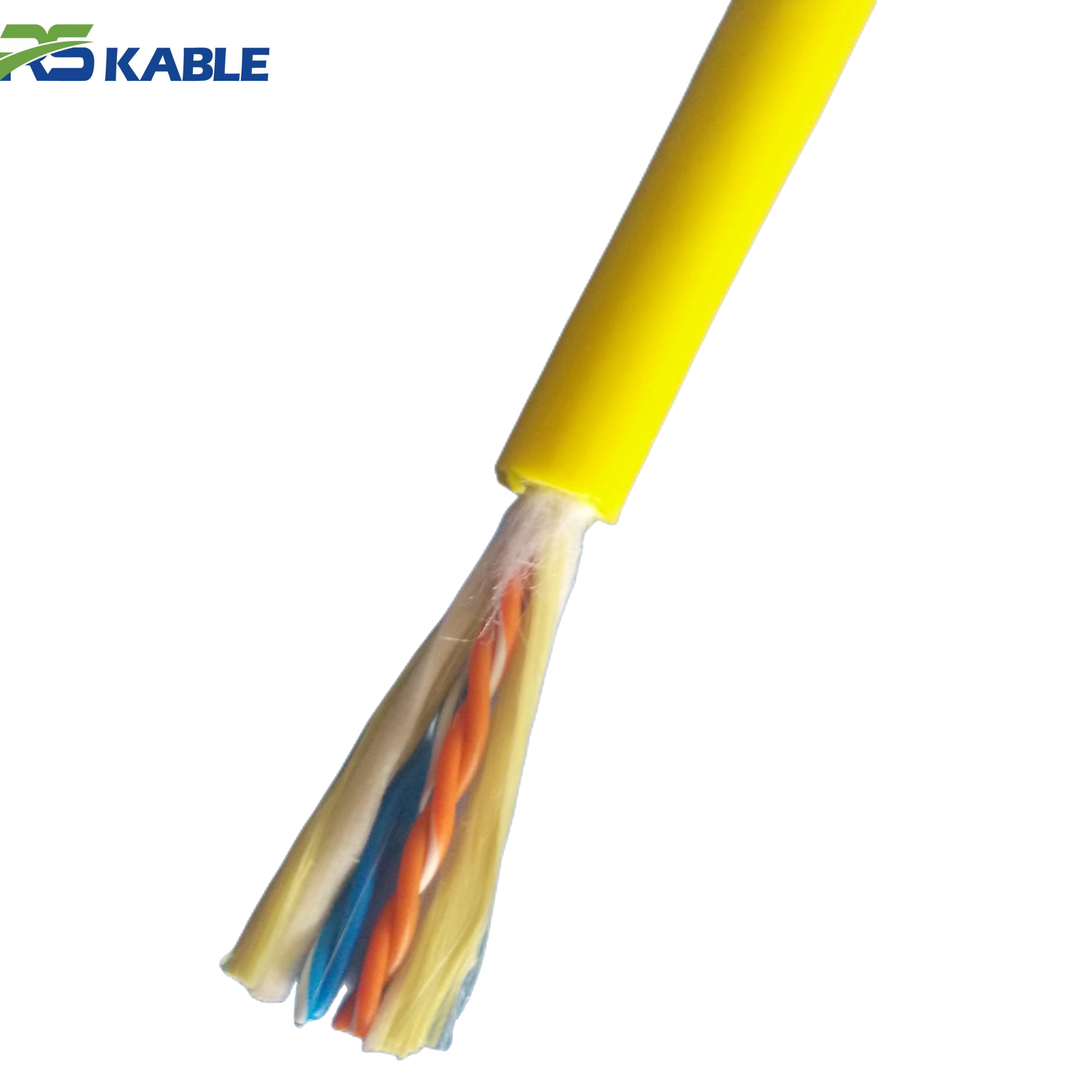
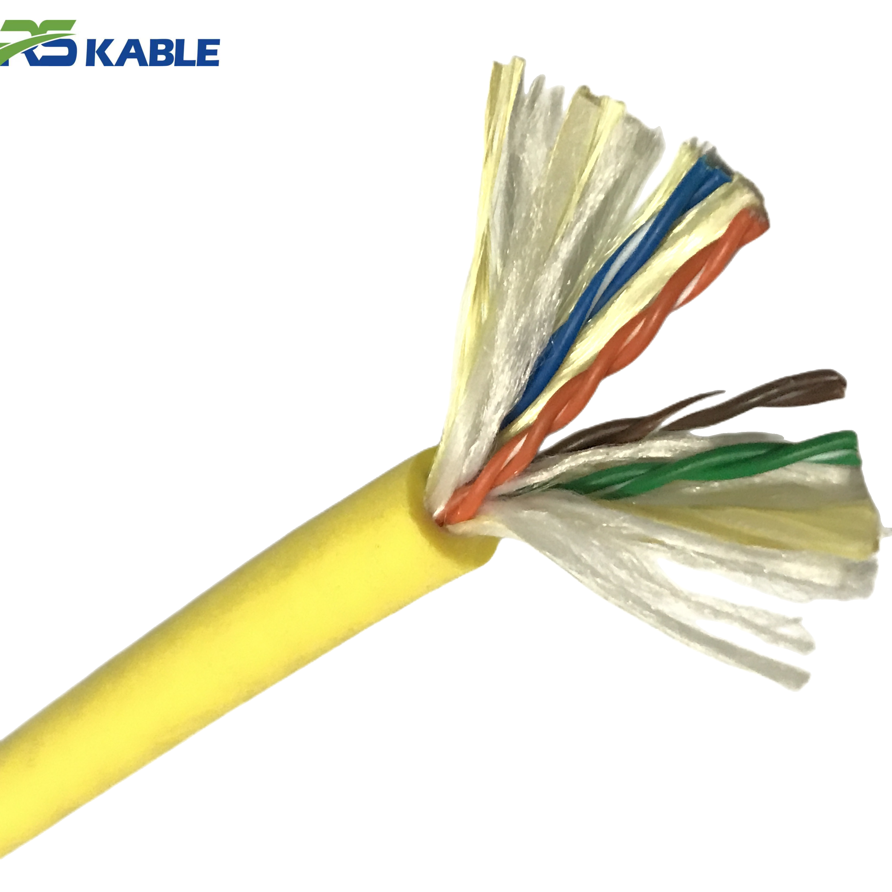
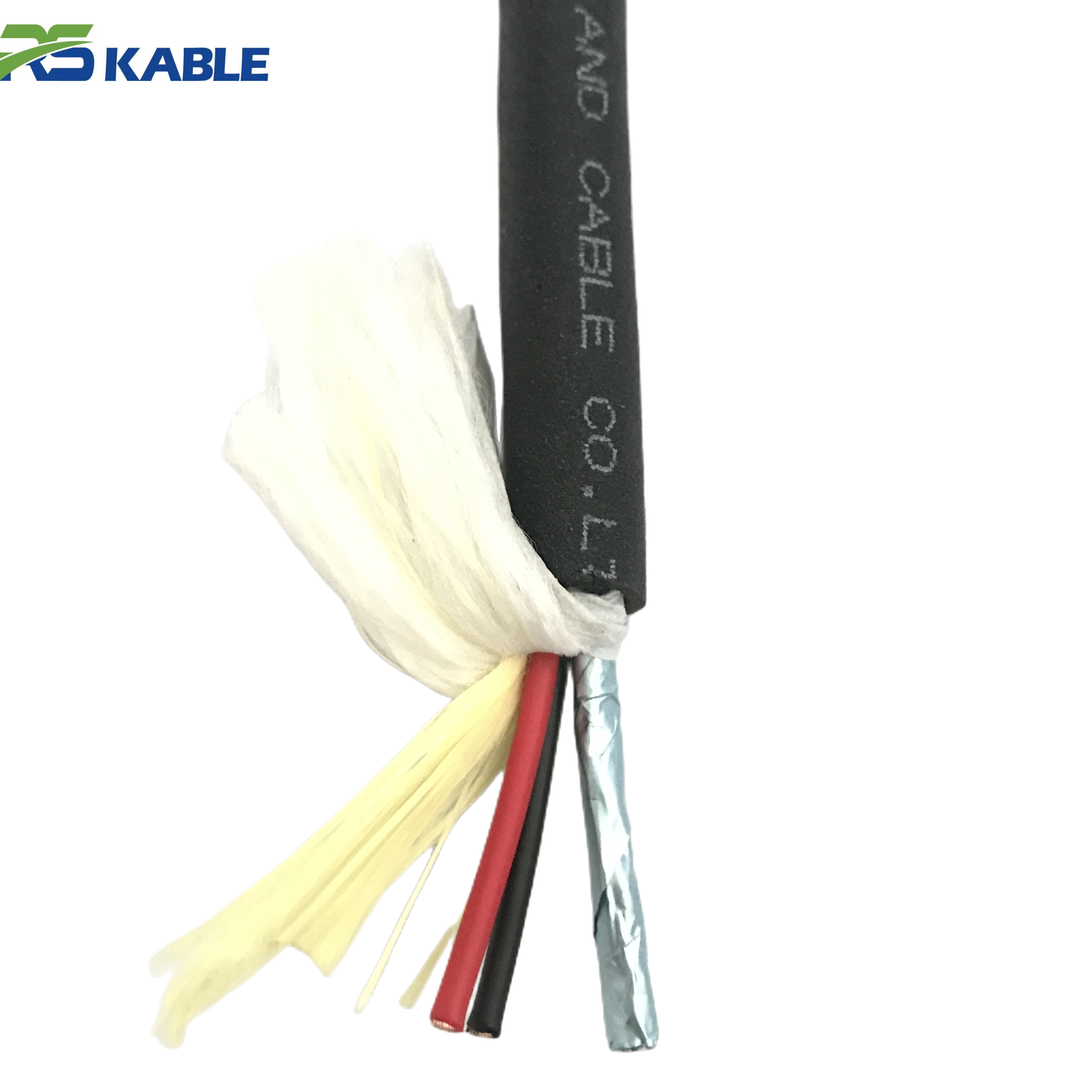
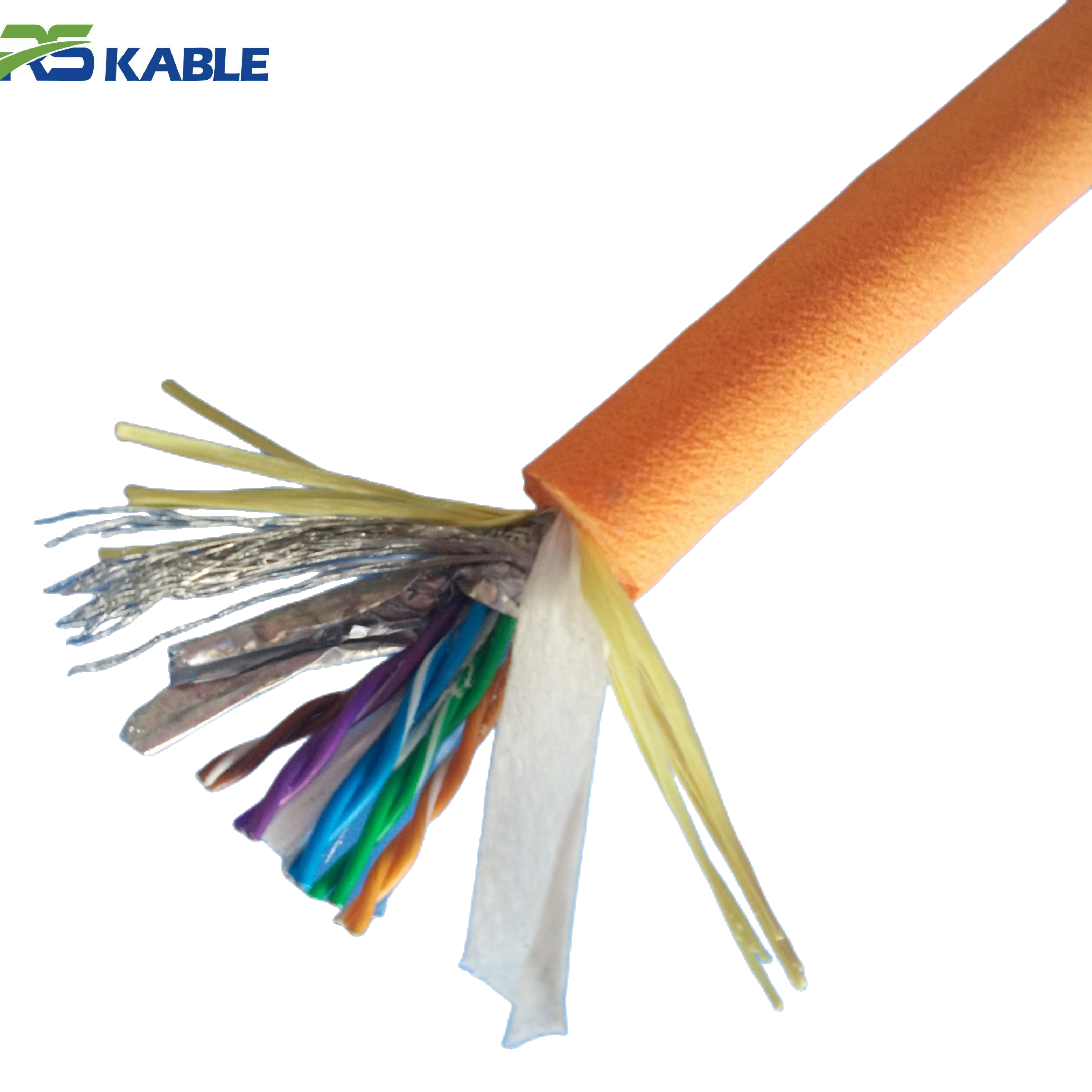
5. Construction Differences Between LV and HV Tethers
Insulation wall thickness
A 48 VDC power conductor uses 0.6–0.8 mm of polyethylene insulation. A 600 VDC conductor requires 1.5–2.5 mm. This affects overall tether diameter and flexibility — even when the conductor itself is thinner in the HV design.
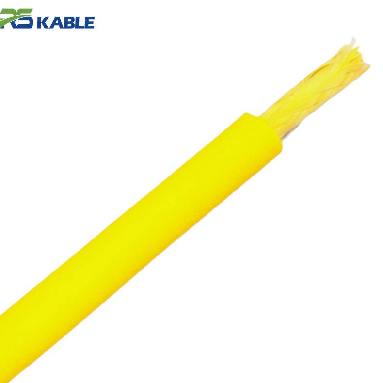
Conductor stranding
HV tethers transmit less current, so they can use smaller conductors. Smaller conductors are easier to strand to high flexibility classes (IEC 60228 Class 5 or Class 6). A well-designed HV tether can match or exceed the bending performance of a comparable LV tether, despite the thicker insulation.
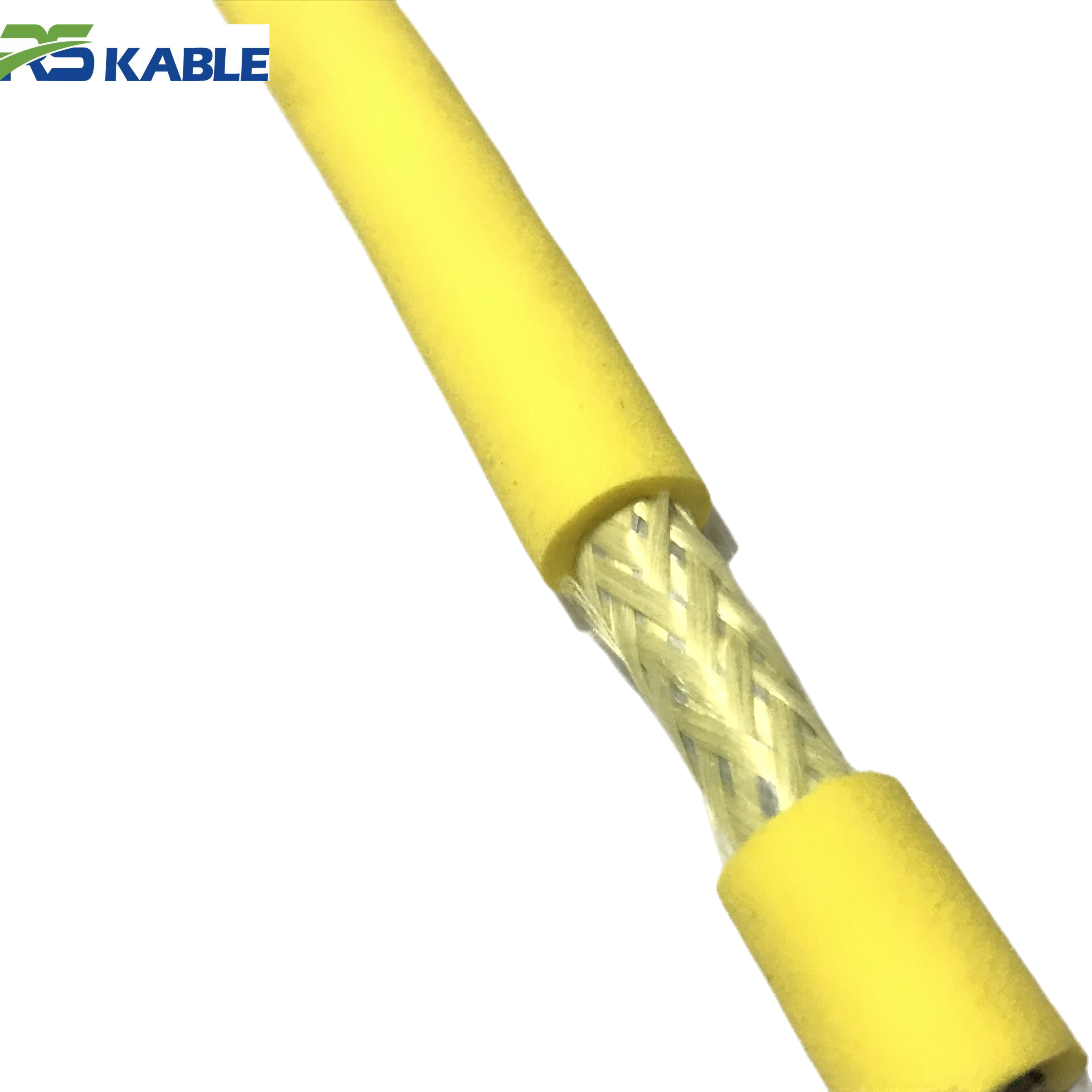
EMI shielding in HV designs
High voltage conductors create stronger capacitive coupling into adjacent signal pairs. The standard mitigation uses individual foil screens on each signal pair, plus an overall signal bundle screen, plus physical separation between power and signal conductors in the cable cross-section. A quality HV tether specification will include crosstalk attenuation data.
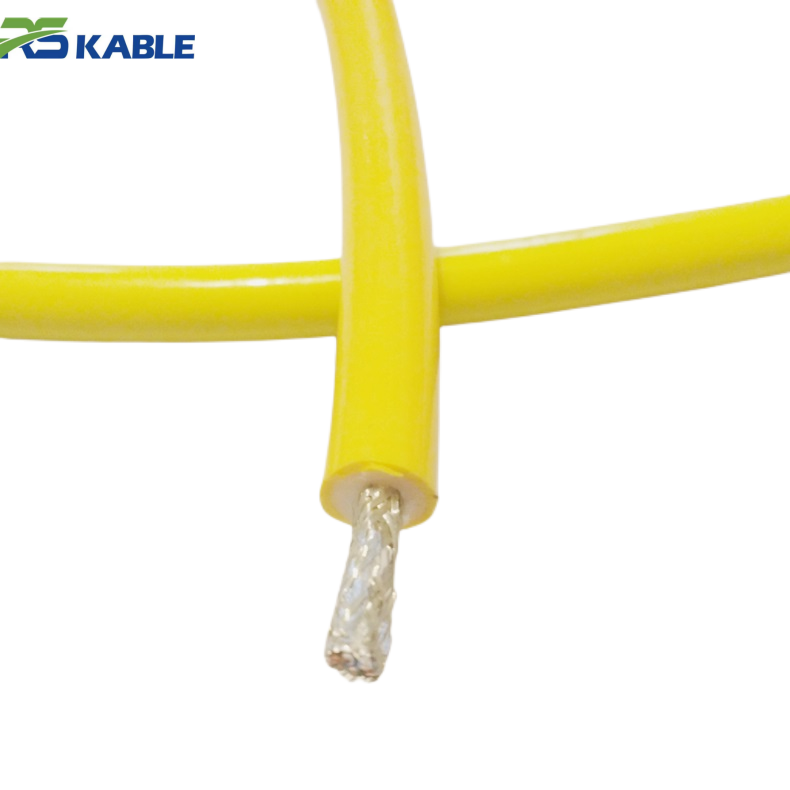
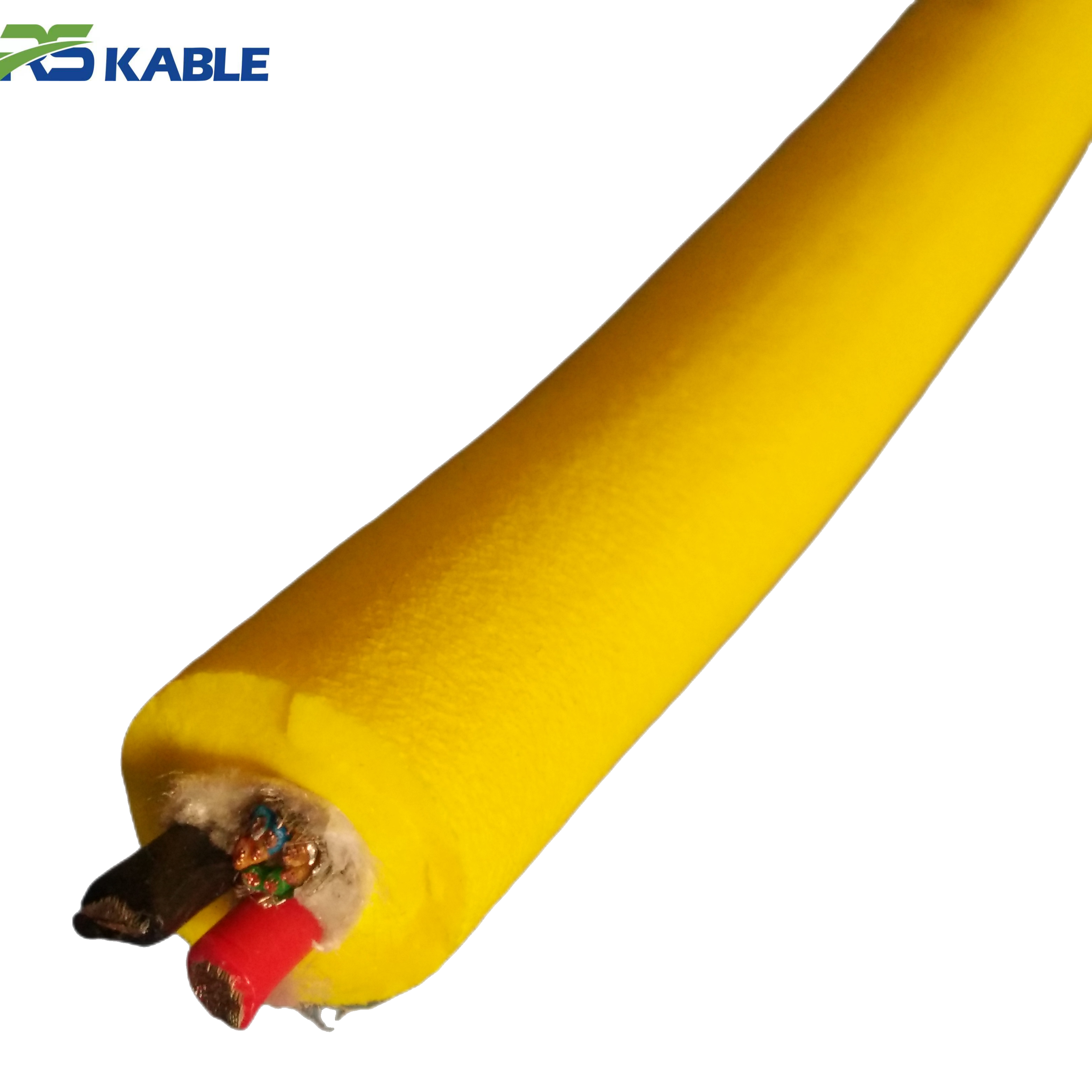
Jacket and depth rating
Deep-rated tethers — LV or HV — require jacket compounds that maintain dimensional stability under high hydrostatic pressure. At 3,000 m, pressure reaches approximately 300 bar. Standard PVC cold-flows under these conditions. High-density polyurethane formulations are the industry standard for deep-rated tethers. This requirement applies regardless of voltage class, but it is almost always paired with HV designs because the depth that demands it also demands HV transmission.
6. Five Questions to Select the Right Architecture
Work through these five questions in sequence. In most cases, the answer becomes clear by question three.
- What is the maximum operating depth? Under 80 m with a light vehicle: LV is almost certainly adequate. Above 200 m: evaluate HV regardless of load.
- What is the peak vehicle load, measured on the bench? Under 400 W: LV is viable to ~200 m. Above 1,000 W at any significant depth: HV is very likely required.
- What conductor size does a LV tether require? Calculate the voltage budget. If the resulting cable is too heavy or stiff for your deployment system, LV is disqualified.
- Can your operation support HV handling requirements? Systems above 60 VDC require trained personnel, interlocked equipment, and documented safety procedures. If not, LV is required.
- What is the total cost of ownership over five years? Heavier LV conductors plus handling penalties often cost more over asset life than the HV converter plus infrastructure. Run both numbers.
Conductor sizing reference — 48 VDC systems, ≤10% drop target:
|
Tether length |
Load |
Min. conductor |
Notes |
|
0–100 m |
Up to 8 A |
1.5 mm² |
Standard for observation-class ROVs |
|
100–200 m |
Up to 8 A |
2.5 mm² |
Approaching drop limit at higher loads |
|
200–300 m |
Up to 10 A |
4 mm² |
Consider HV above 8 A at this range |
|
300–500 m |
Up to 8 A |
6 mm² |
HV strongly recommended |
|
> 500 m |
Any |
HV required |
LV not viable — conductor size becomes unmanageable |
Table 4. Conductor sizing guide for 48 VDC LV systems. Derate one conductor size for drum-spooled tether under sustained load (temperature correction).
Selection summary: LV (≤48 VDC): depth under 100 m, load under 500 W, simple operations. | HV (≥150 VDC): depth over 200 m, load over 800 W, professional deployment. | Mid-range (48–150 VDC): often the rational choice for the space between both envelopes.
7. Making the Decision at Specification, Not in the Field
Lock in the architecture early
The ROV cable voltage decision should be made during system specification — before the vehicle’s power distribution is designed. A vehicle built for LV supply has different architecture than one built for HV. Retrofitting the other architecture after manufacture is expensive and technically complex.
The two mistakes that repeat
The first: specifying LV because it was used on the last project. Without checking whether the new project’s depth and load fit within LV limits, this produces under-powered systems.
The second: specifying HV because it sounds more capable. Without evaluating whether the application needs it or whether the organization can support it safely, this adds cost and complexity with no benefit.
Both errors are prevented by running the five questions above at the start of the design process. The arithmetic is straightforward. The discipline to do it before committing to a tether specification is what separates reliable systems from expensive remediation projects.
Specifying a tether for a new ROV program? Our applications team provides free voltage architecture reviews for new cable inquiries. Send your tether length, depth rating, and vehicle power budget. We will return a written recommendation with conductor sizing and voltage budget calculations.
Frequently Asked Questions
Q1: What exactly is the boundary between low and high voltage ROV cable?
In IEC 60038 terms, low voltage extends to 1,000 VAC or 1,500 VDC — a boundary not very useful for ROV tether selection. In practice, the meaningful threshold is 60 VDC, where IEC 62368-1 classifies circuits as hazardous voltage. This triggers mandatory safety controls: interlocked enclosures, insulated tools, and trained personnel. In the ROV industry, “high voltage tether” typically means transmission above 150 VDC. The 60–150 VDC zone is technically low voltage but requires some HV-style precautions. When specifying a tether, always confirm the rated insulation voltage of the cable and cross-check against your transmission voltage with appropriate margin.
Q2: Can I raise my surface PSU voltage to fix a marginal LV system?
Yes — within limits. You can increase supply voltage up to the tether’s rated insulation voltage, typically 300 V or 600 V on standard LV cables. However, most LV ROV components are rated for 48 VDC maximum input. Supplying 72 VDC directly to 48 V-rated electronics risks component damage. You would need onboard DC-DC converters — which means you have effectively built a mid-range HV architecture. If you are going to add converters anyway, specify the tether voltage class correctly from the start rather than retrofitting the architecture after the cable is built.
Q3: How does HV transmission affect EMI in the tether’s signal conductors?
High voltage conductors create stronger capacitive coupling into adjacent signal pairs compared to low voltage conductors carrying the same power. The standard mitigation combines: individual foil screens on each signal pair, an overall signal bundle screen, physical separation between power and signal conductors in the cable cross-section, and controlled lay lengths to reduce inductive coupling. A properly designed HV tether will include crosstalk attenuation data in its specification sheet. If a supplier cannot provide this, treat it as a red flag. Fiber optic elements in the tether bypass this problem entirely for high-bandwidth data links.
Q4: What safety systems are required for a high-voltage ROV tether installation?
IEC 62368-1 classifies circuits above 60 VDC as hazardous energy sources. Minimum requirements include: physical interlocks preventing energization while connectors are accessible; insulated tools and PPE rated for the transmission voltage; documented lockout/tagout procedures; and training records for all personnel near the topside equipment. Offshore deployments under classification society rules (DNV, Lloyd’s, ABS) add requirements for cable routing, segregation, and earthing architecture. These controls are not bureaucratic overhead — at 300 VDC with 5 A flowing, contact with a damaged connector can be fatal. The controls reflect real risk.
Q5: When does it make sense to add fiber optic elements to a tether?
Fiber becomes attractive under three conditions. First, when bandwidth exceeds what shielded copper pairs can deliver reliably over the tether length — roughly above 100 Mbps beyond 200 m. Second, when the electromagnetic environment is severe enough to compromise copper signal integrity despite good shielding. Third, when tether weight and flexibility are critical and replacing signal copper with fiber reduces cable diameter and weight meaningfully. Fiber is also inherently immune to HV-to-signal crosstalk. In HV tether designs with high bandwidth requirements, fiber is often the cleanest path to reliable signal transmission.
Q6: How does voltage class affect the ROV’s neutral buoyancy design?
Significantly. Conductor mass is a major contributor to tether weight-in-water. A LV tether with large conductors — for example, 6 mm² at 300 m — is considerably denser than an HV tether using 1.5 mm² conductors for the same power delivery. This weight difference affects two things. First, drag force on the ROV during lateral movement, which determines station-keeping power and thruster sizing. Second, the amount of buoyancy foam required in the tether or vehicle to achieve neutral buoyancy. Transitioning from LV to HV sometimes eliminates the need for external buoyancy modules entirely, simplifying the deployment system.