High Voltage ROV Cable for Offshore Oil & Gas: Design, Specifications, and Safety Standards
Offshore oil and gas operations depend heavily on subsea robotics for inspection, intervention, drilling support, and asset integrity management. In deepwater and ultra-deepwater environments, reliable power transmission becomes a defining engineering challenge. At the center of this challenge lies the high-voltage ROV Cable, a critical subsea power and signal transmission system engineered to withstand hydrostatic pressure, dynamic mechanical loads, and long-distance voltage drop constraints.
This technical research article explores the electrical design logic, structural architecture, failure mechanisms, compliance requirements, and emerging innovations in high-voltage ROV tether systems used in offshore oilfields such as the North Sea, Gulf of Mexico, and South China Sea.
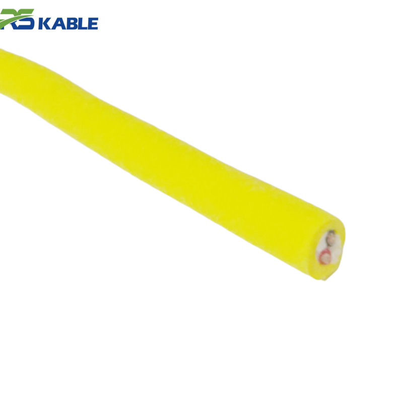
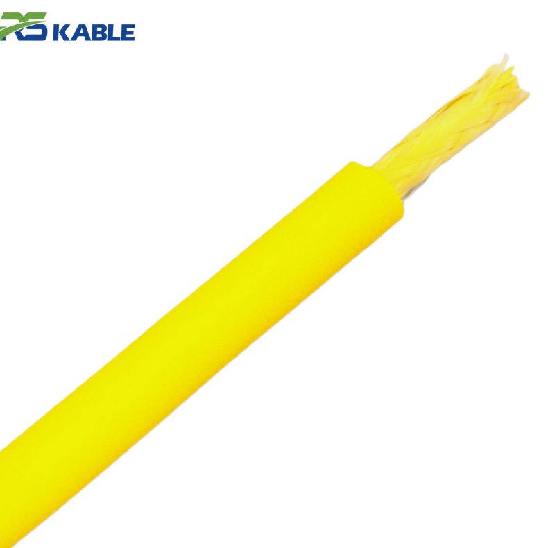
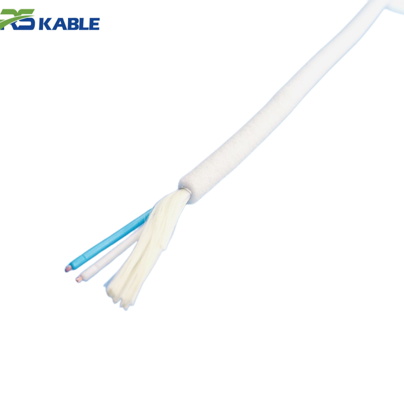
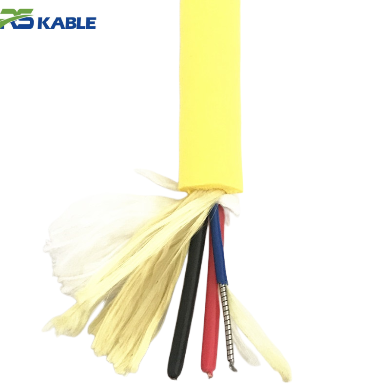
Aquaculture Monitoring ROV Cable – Lightweight Construction, Reduced Equipment Load
This ROV cable is engineered for aquaculture monitoring systems with a **lightweight construction** that reduces equipment load and enhances maneuverability in subsea environments. It’s optimized for efficient power and signal delivery while minimizing physical burden on remotely operated vehicles.:contentReference
1. Operational Context: Deepwater Power Transmission Challenges
1.1 Environmental Constraints in Offshore Oilfields
Modern offshore intervention systems operate at depths ranging from 500 meters to over 3000 meters. These environments introduce:
-
Hydrostatic pressure exceeding 300 bar
-
Continuous dynamic bending from vessel heave
-
Saltwater-induced corrosion
-
Long cable deployment lengths
-
High electrical load demand (150–400 kW typical)
Unlike conventional marine cables, a high-voltage ROV tether must simultaneously function as a power transmission line, data backbone, and mechanical load-bearing member. Failure in any one of these domains can terminate offshore operations, where downtime costs may exceed six figures per day.
1.2 Power Demand Requirements in Modern ROV Systems
Deepwater ROV systems integrate hydraulic pumps, thrusters, lighting arrays, sonar, and high-definition cameras. These loads demand stable medium-voltage input with minimal harmonic distortion and limited voltage drop.
1.3 Mechanical and Electrical Dual-Function Requirement
The ROV Cable must deliver power while sustaining tensile loads during deployment and retrieval through tether management systems (TMS). This dual-role engineering requirement differentiates subsea ROV systems from standard marine cable designs.
2. Electrical Design Architecture of High Voltage ROV Cable
2.1 Voltage Rating Selection and System Optimization
Common offshore voltage classes include:
-
3.6/6 kV
-
6/10 kV
-
8.7/15 kV
Higher voltage reduces current and mitigates resistive losses over long subsea distances. However, insulation thickness and cable weight increase proportionally, affecting deployment mechanics and buoyancy balance.
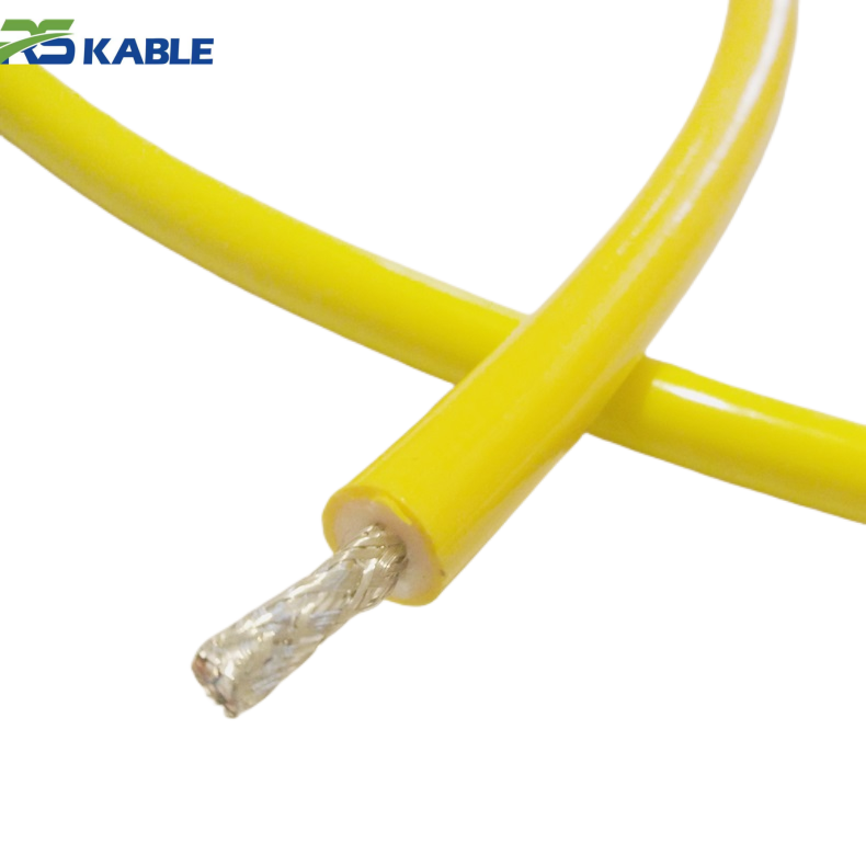
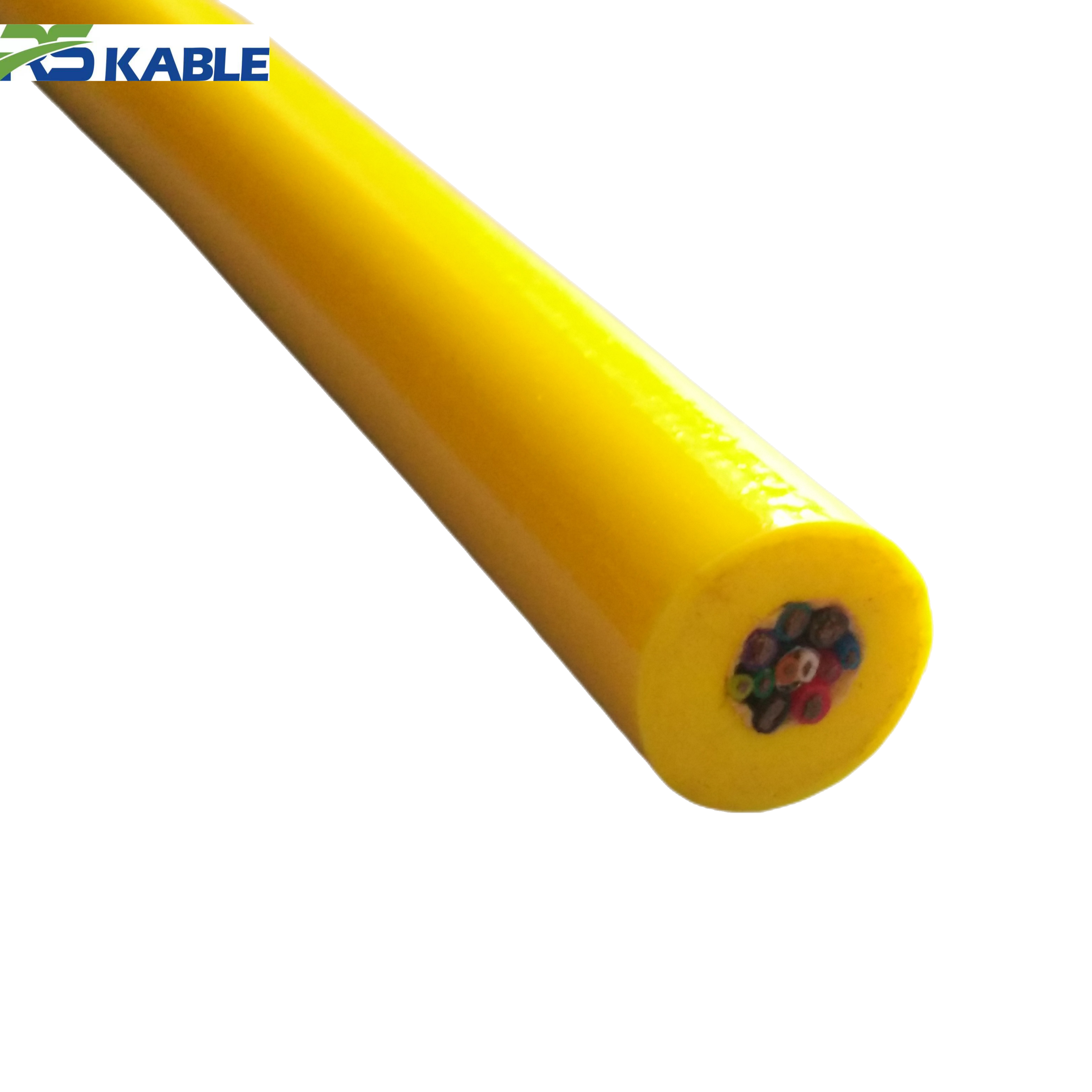
2.2 Conductor Engineering and Resistance Control
High-voltage designs typically use:
-
Class 5 or Class 6 stranded copper (IEC 60228)
-
Tinned copper for corrosion resistance
-
Cross-sections between 16 mm² and 70 mm²
Key electrical parameters include:
-
DC resistance at 20°C
-
AC impedance
-
Short-circuit withstand capacity
-
Thermal rise under load
2.3 Thermal Performance and Short-Circuit Withstand Capacity
Thermal stability ensures safe operation under continuous load and fault conditions. Proper conductor sizing prevents excessive insulation degradation.
3. Engineering Calculation Example: Voltage Drop in 1200m Deployment
3.1 Input Parameters and System Assumptions
Consider a 6.6 kV system transmitting 250 kW to an ROV at 1200 meters.
Assumptions:
-
Conductor size: 25 mm²
-
Copper resistivity: 0.0175 Ω·mm²/m
-
Current ≈ 21.9 A
3.2 Resistance Calculation Methodology
Total loop resistance (2400m round trip):
R = (0.0175 × 2400) / 25
R ≈ 1.68 Ω
3.3 Voltage Drop and Efficiency Analysis
Voltage drop:
Vdrop = I × R ≈ 36.8 V
Percentage drop:
(36.8 / 6600) × 100 ≈ 0.56%
3.3.1 Impact of Conductor Cross-Section on Loss Reduction
This analytical validation demonstrates why medium-voltage architecture significantly improves efficiency in long subsea runs.
4. Insulation Systems and Hydrostatic Pressure Resistance
4.1 XLPE vs EPR: Material Performance Comparison
Two dominant insulation systems:
-
EPR (Ethylene Propylene Rubber)
-
XLPE (Cross-Linked Polyethylene)
Performance requirements include:
-
High dielectric strength
-
Low water absorption
-
Resistance to water treeing
-
Stability under compressive hydrostatic stress
4.2 Water Blocking and Moisture Migration Prevention
Water-blocking tapes and radial barriers are integrated to prevent longitudinal water migration.
4.2.1 Water Treeing Mechanism in High Voltage Systems
Water treeing results from long-term moisture exposure under electrical stress, eventually leading to dielectric breakdown.
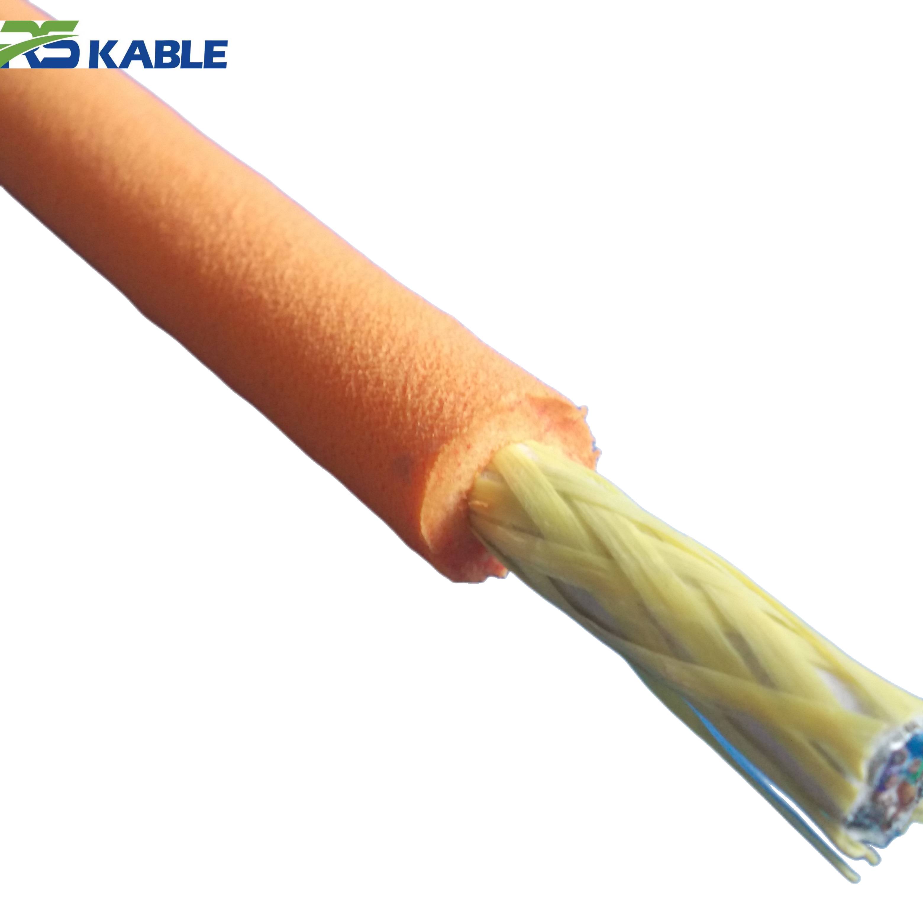
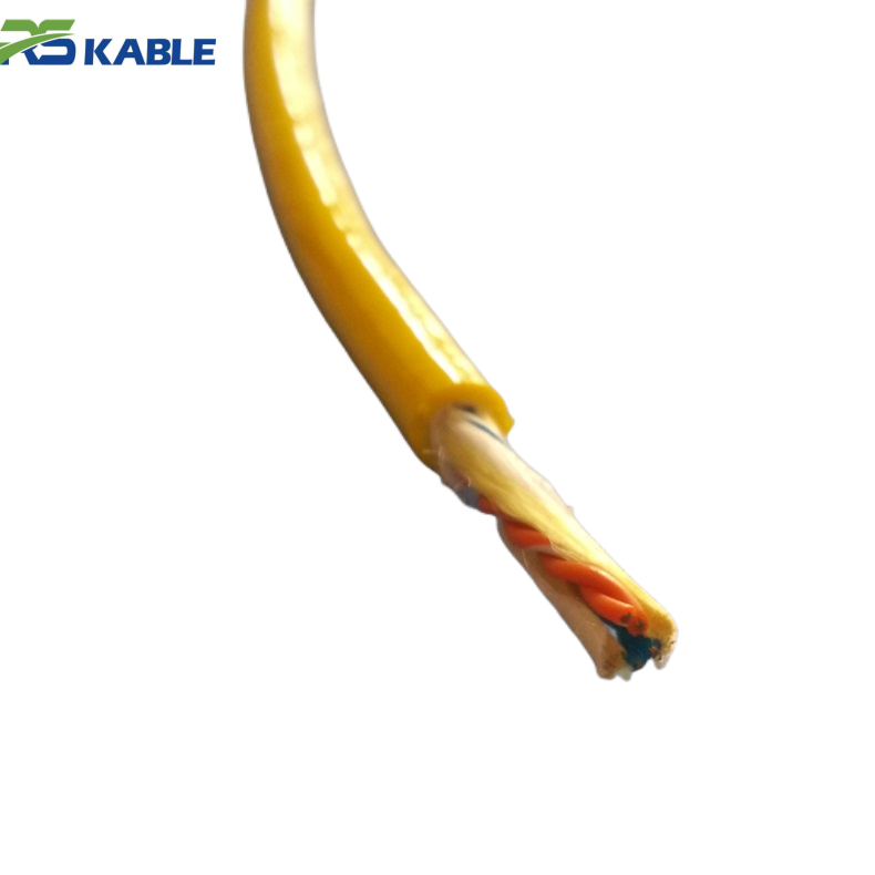
5. Mechanical Reinforcement and Dynamic Load Performance
5.1 Steel Armor vs Aramid Strength Members
Reinforcement options include:
-
Galvanized steel armor
-
Aramid fiber tensile members
-
Hybrid composite strength cores
5.2 Tensile Rating and Fatigue Cycle Validation
Key metrics:
-
Tensile rating (50–250 kN)
-
Minimum bending radius
-
Crush resistance
-
Fatigue cycle tolerance
5.2.1 Dynamic Bending Under Tether Management System (TMS)
Cyclic bending simulations replicate vessel heave and tether motion to validate mechanical durability.
6. Common Failure Modes in Offshore High-Voltage ROV Systems
6.1 Insulation Water Treeing and Dielectric Breakdown
Mitigation:
-
High-quality XLPE compounding
-
Strict manufacturing cleanliness
-
Partial discharge testing
6.2 Armor Fatigue Fracture in Deepwater Cycles
Mitigation:
-
Fatigue-rated armor design
-
Proper drum handling
-
TMS tension control
6.3 Outer Sheath Hydrolysis and Polymer Degradation
Mitigation:
-
Marine-grade polyurethane (PUR)
-
UV stabilization additives
6.4 Shield Grounding and Electromagnetic Interference Risk
Mitigation:
-
Verified copper braid continuity
-
Proper bonding at topside termination
7. International Standards and Offshore Certification Framework
7.0 IEC and IEEE Medium Voltage Compliance
Relevant standards include:
-
IEC 60092
-
IEC 60502
-
IEEE 45
7.1 Hydrostatic Pressure and Type Testing Procedures
Testing may include:
-
High-voltage withstand testing
-
Pressure chamber simulation
-
Mechanical tensile validation
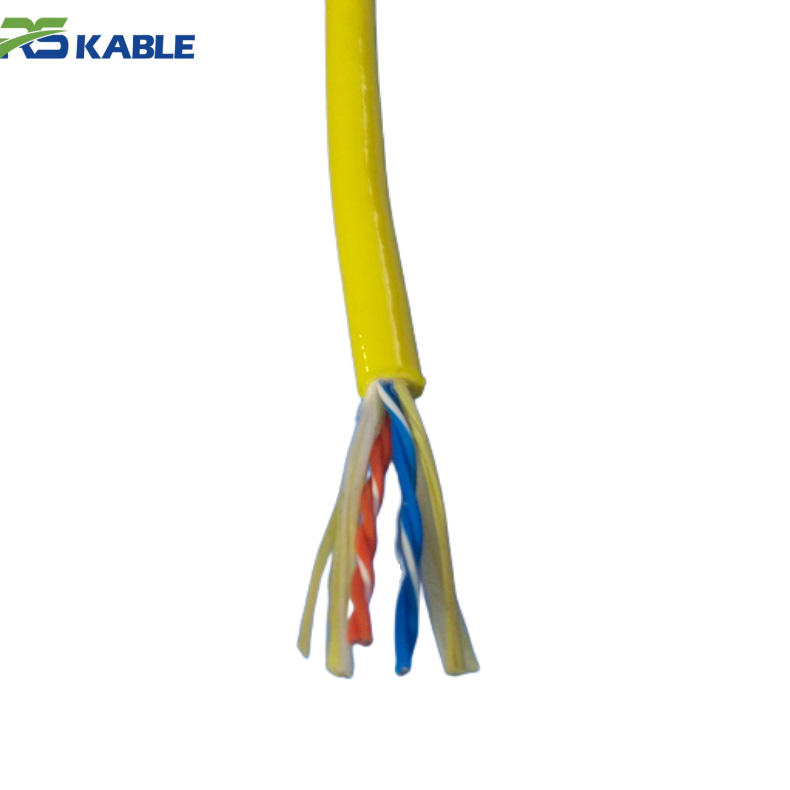
8. Integration with Subsea Power and Electro-Optical Systems
8.1 Subsea Power Umbilical Coordination
8.2 Electro-Optical Composite Cable Architecture
8.3 EMI Control in Hybrid Transmission Systems
High-voltage transmission must coexist with fiber-optic telemetry without electromagnetic interference.
9. Emerging Trends in Ultra-Deepwater High Voltage Transmission
9.1 10kV+ Architecture Development
9.2 Lightweight Composite Armor Innovation
9.3 Embedded Monitoring and Smart Cable Systems
As offshore energy exploration expands into deeper environments, the design complexity of the ROV Cable continues to evolve.
10. Strategic Engineering Selection Criteria
10.1 Depth Rating vs Power Demand Balance
10.2 Lifecycle Cost and Risk Assessment
10.2.1 Failure Cost vs Design Margin Optimization
Subsea cable failure typically results from cumulative electrical, mechanical, and environmental stress factors rather than a single cause.
FAQ: High Voltage Offshore ROV Cable Technical Questions
What voltage class is optimal for 1000m+ depth?
6/10 kV is common, though higher loads may justify 8.7/15 kV systems.
How is hydrostatic pressure resistance validated?
Through controlled pressure chamber testing simulating deployment depth.
Why is medium voltage preferred over low voltage?
It reduces current, thermal loading, and resistive losses.
What is the most common mechanical failure?
Armor fatigue from cyclic bending.
How long can a high-voltage offshore cable last?
Properly engineered systems may exceed 5–8 years depending on duty cycles.