Fiber Optic ROV Cable: Real-Time Video and Telemetry Transmission Explained
A stable live feed is the difference between efficient inspection and cautious guessing. When video stays clean during turns, the pilot works close to assets with confidence. When telemetry is continuous, the team trusts depth, heading, and system status. When the link drops only during movement, hours disappear into troubleshooting—and the “problem” often isn’t the camera or the software. It’s mechanical stress in the tether.
Fiber optics are widely used in ROV tethering because they support high bandwidth and resist electrical noise. But offshore reliability doesn’t come from “having fiber.” It comes from how the fiber is protected, terminated, routed, tested, and handled. This guide explains the transmission path, the failure patterns crews actually see, and the practical steps that keep real-time video and telemetry stable throughout a shift.
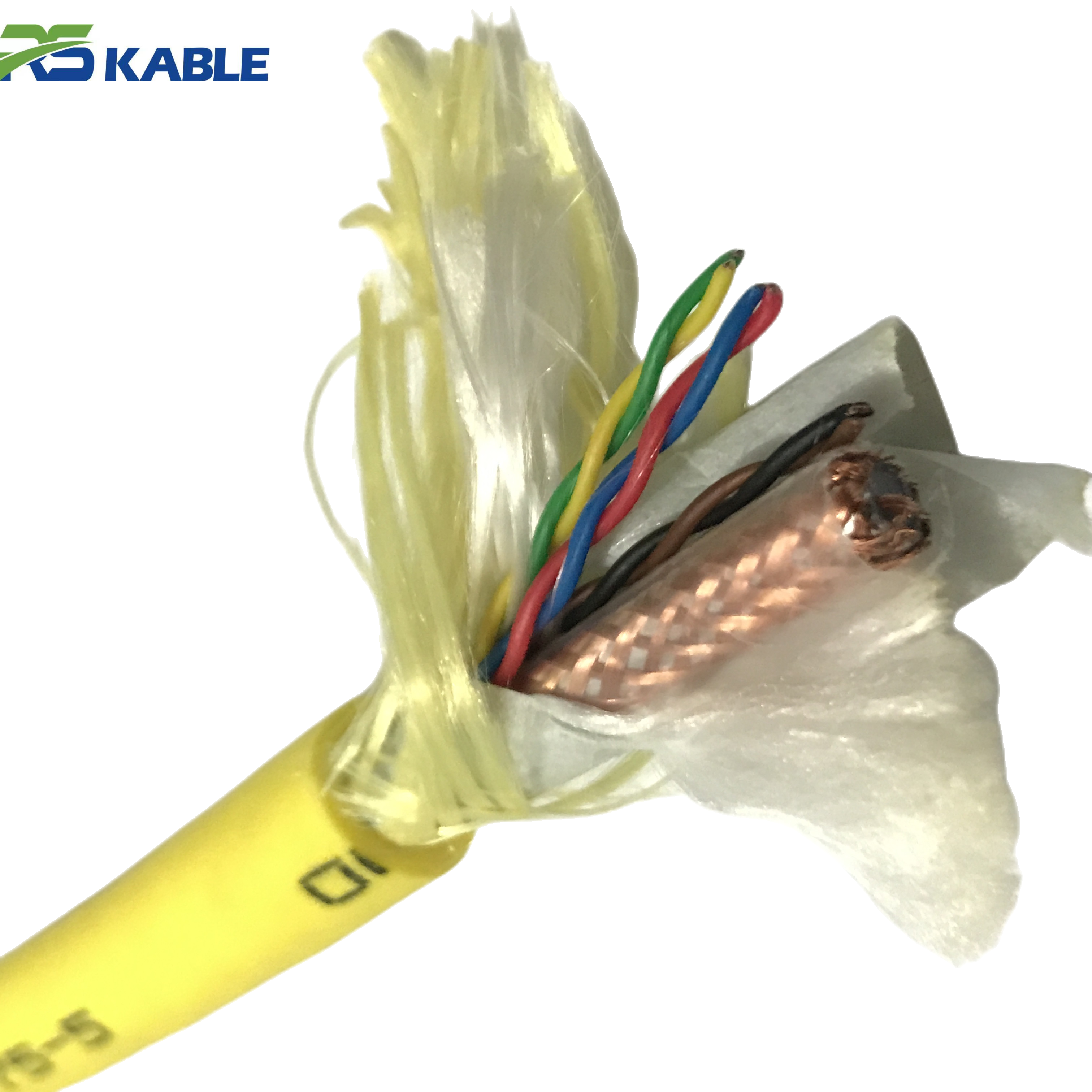
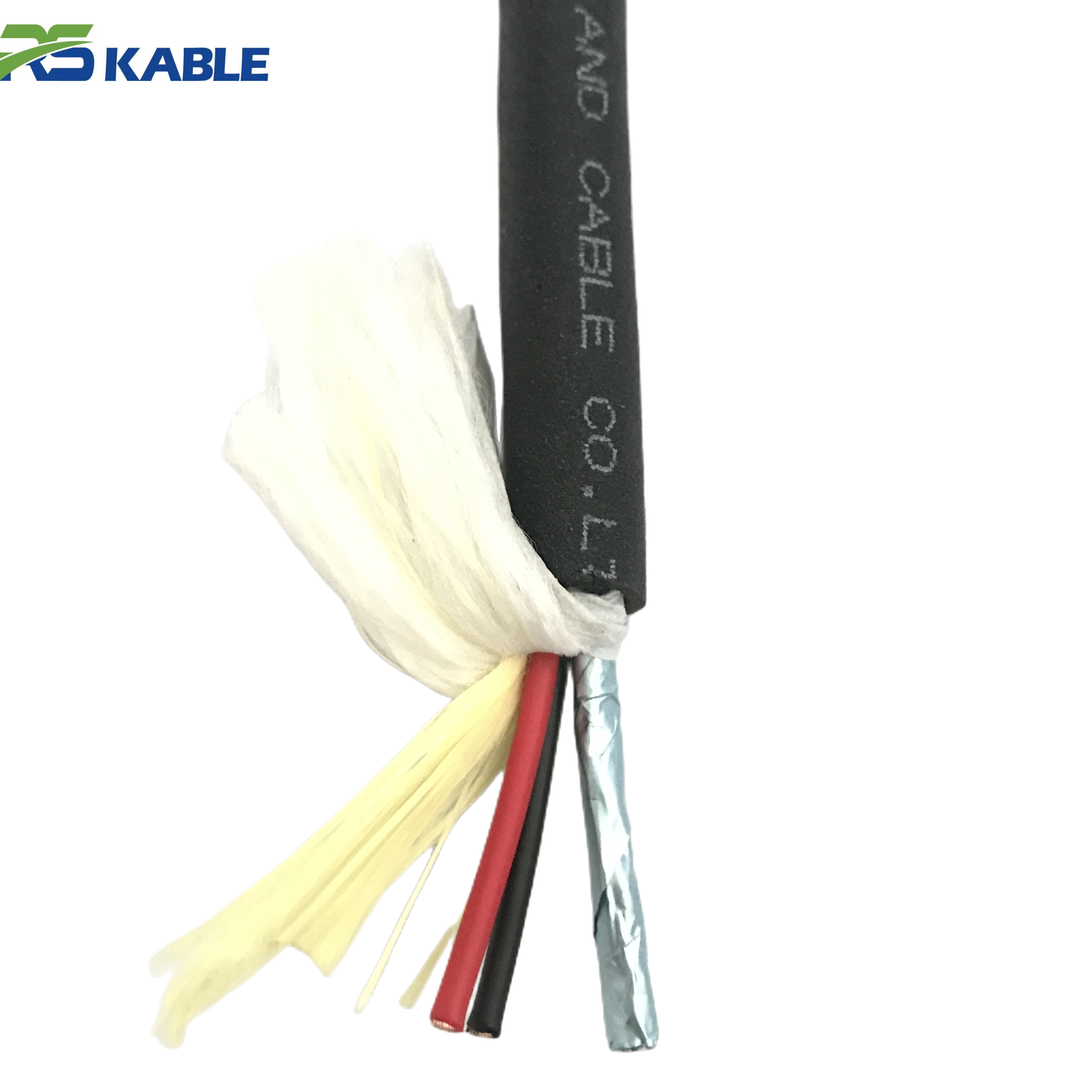
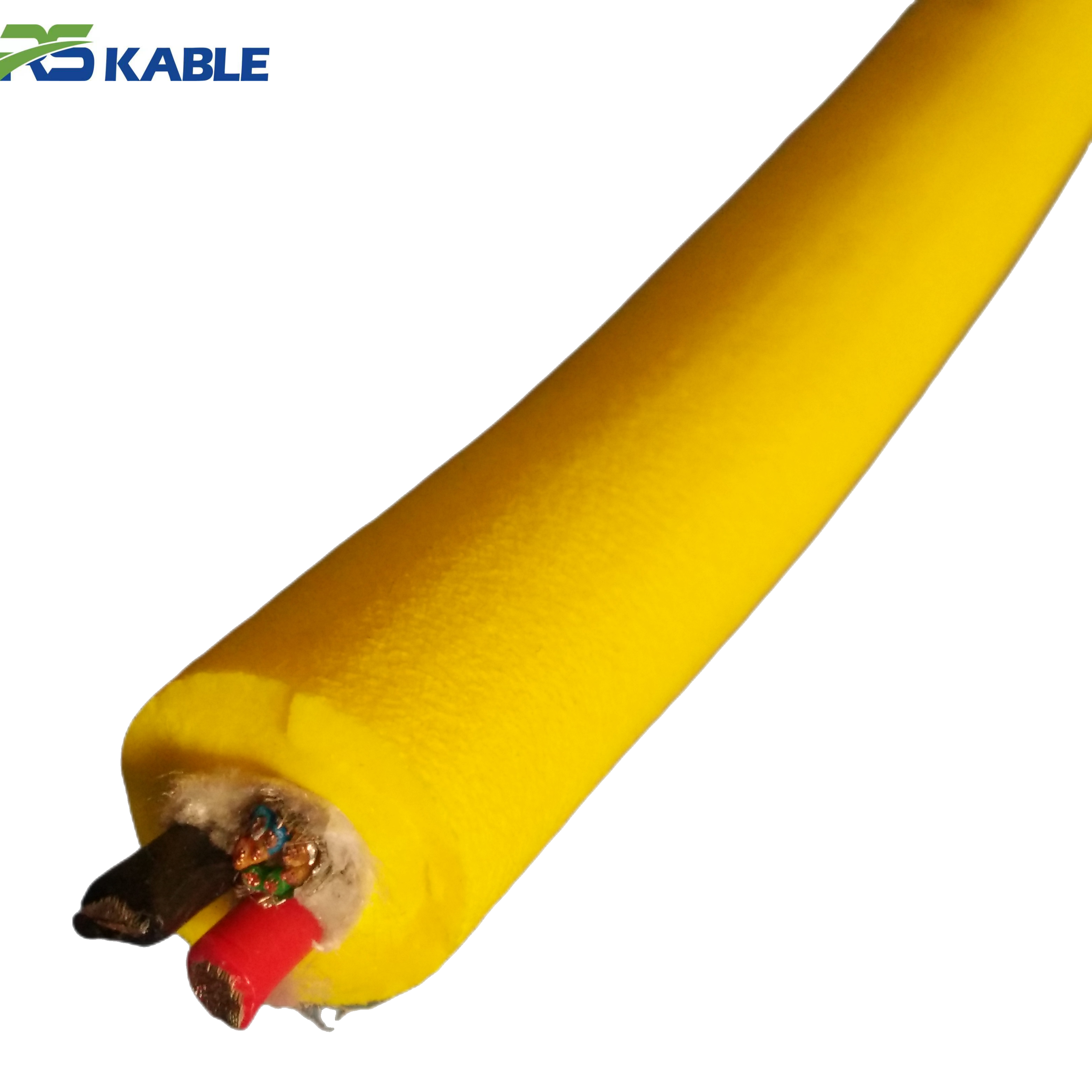
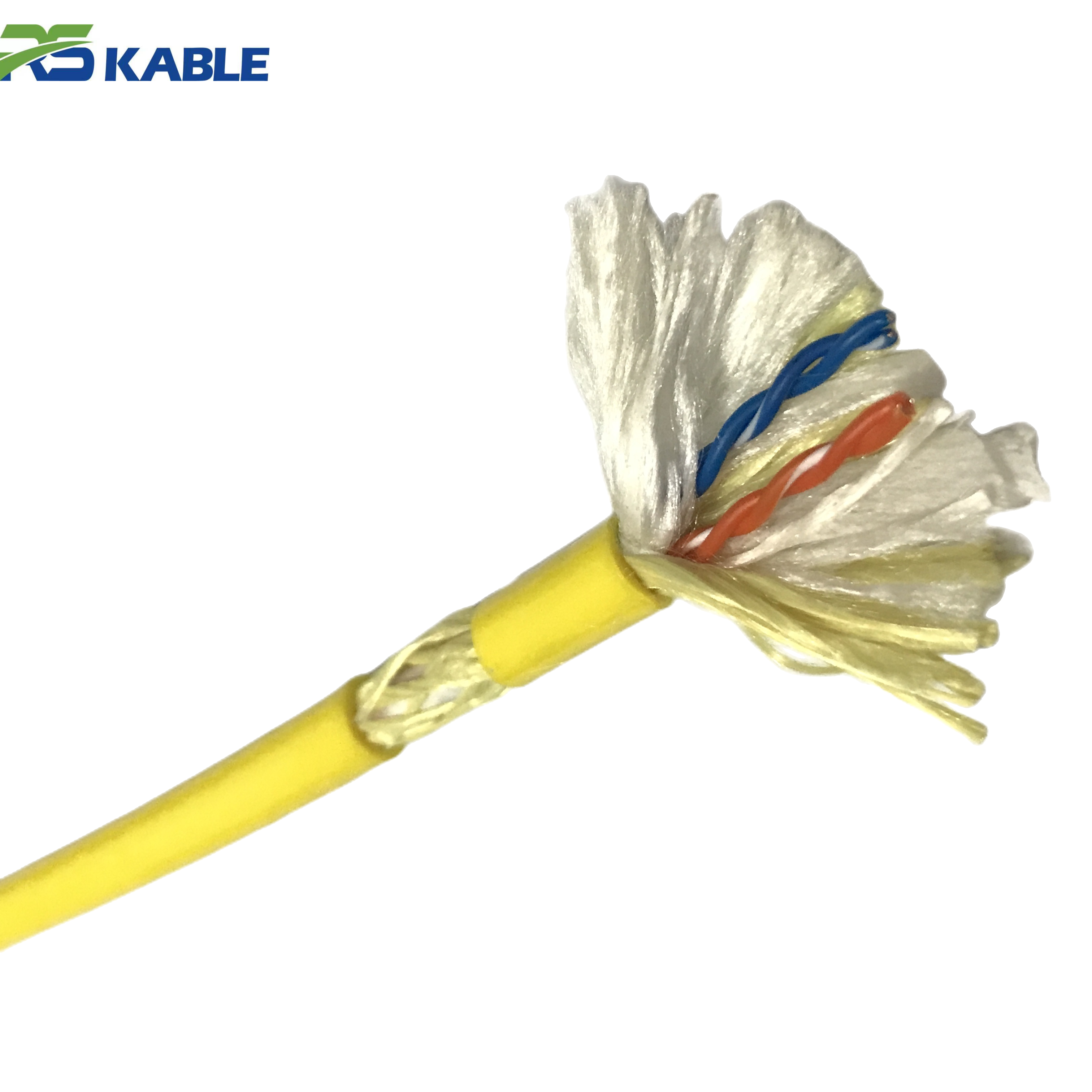
Custom High-Flex Hybrid Umbilical ROV Cable | Power, Coaxial, Signal & Fiber Optic Integration
This **custom-engineered umbilical cable** is the ultimate solution for complex **subsea ROV systems**, integrating **power, coaxial, signal, and fiber optic components** into a single high-flex structure. Designed for multi-functional underwater missions, it ensures seamless data telemetry and robust power delivery while maintaining superior durability in high-pressure deep-sea environments.
Three short field cases that explain most fiber issues
Case 1: Perfect on the dock, unstable during turns offshore
The system passed bench checks. On the first job, video flickered only when the vehicle turned hard or changed depth quickly. Baseline optical measurements taken afterward showed increased loss localized near the end of the tether.
What happened: repeated tight bending concentrated near the termination created micro-bending loss.
Takeaway: movement-only dropouts are usually mechanical stress near the termination, not “bad fiber.”
Case 2: Hard recovery day, then “random” glitches for weeks
After a difficult recovery, the feed began showing brief pixelation during motion. The cable looked fine from the outside. A later comparison to pre-job baseline loss data showed a measurable change on specific channels.
What happened: a crush or hard-spot event altered internal geometry on the drum layer.
Takeaway: baseline measurements make post-event diagnosis fast and objective.
Case 3: Added more fibers, got worse control
A project increased fiber capacity and protective layers. Data improved, but the tether OD increased and drag rose in current. Sweep zone widened, forcing slower passes near structures.
What happened: the system optimized data without controlling hydrodynamics.
Takeaway: fiber capability must be balanced with handling and drag, especially in strong current.
What “real-time” transmission means in ROV operations
Real-time performance is not just bandwidth. Offshore, it means:
-
low, consistent latency (pilot confidence)
-
stable video quality during motion, not only when hovering
-
continuous telemetry without intermittent gaps
-
predictable behavior after routine handling and reeling cycles
-
resilience when thrusters and tooling load the power system
A link that is fast but unstable during movement is not a real-time link in practice.
Why fiber is used: bandwidth and noise immunity, yes—but stability is the goal
Copper pairs can carry data, and some systems still use copper for certain signals. Fiber becomes the preferred backbone when you need:
-
multiple live video streams
-
higher resolution inspection workflows
-
long working lengths
-
improved immunity to electrical noise from power conductors and tools
-
stable telemetry and sensor feeds with low latency
That is why a fiber-capable ROV Cable is common in inspection, survey, and many intervention missions.
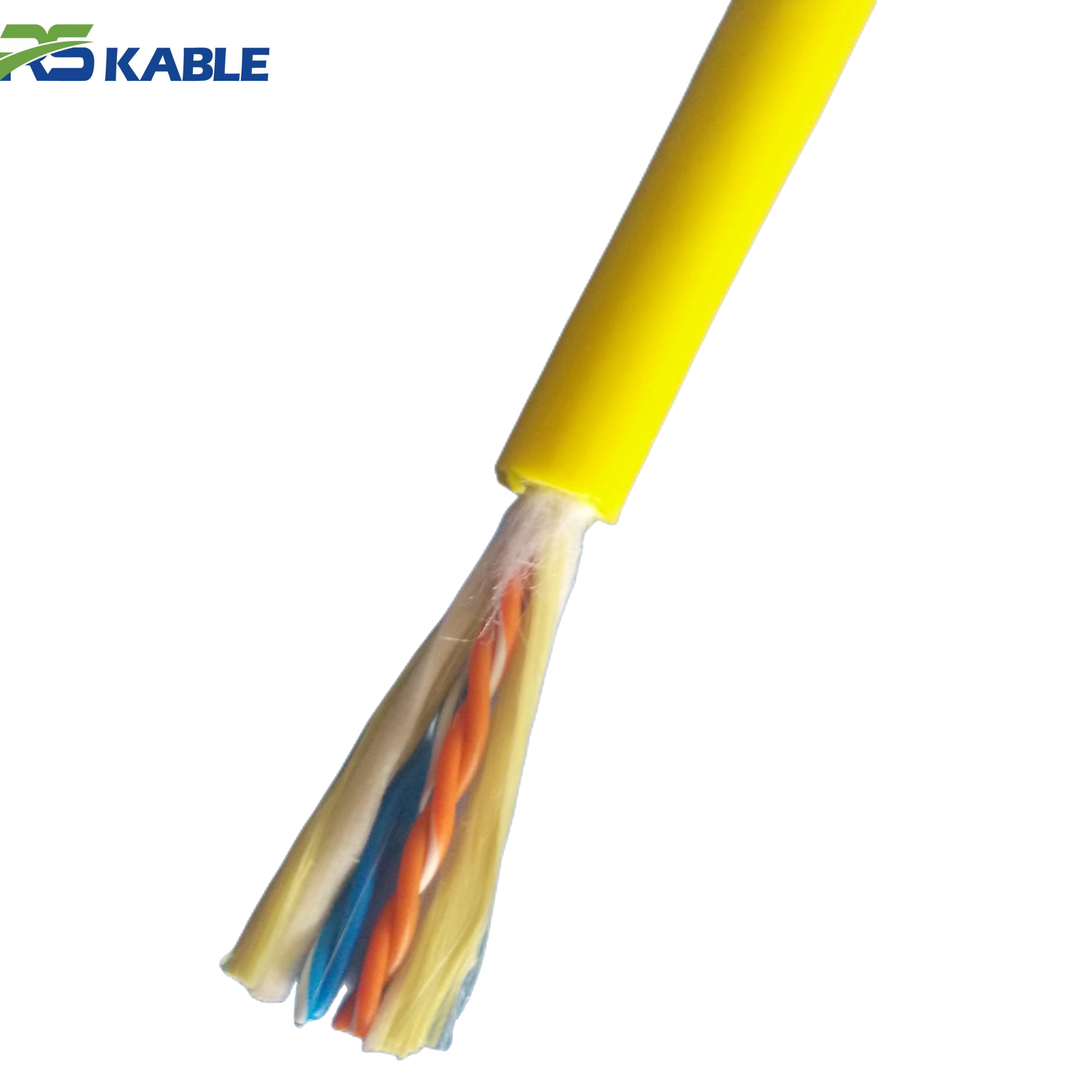
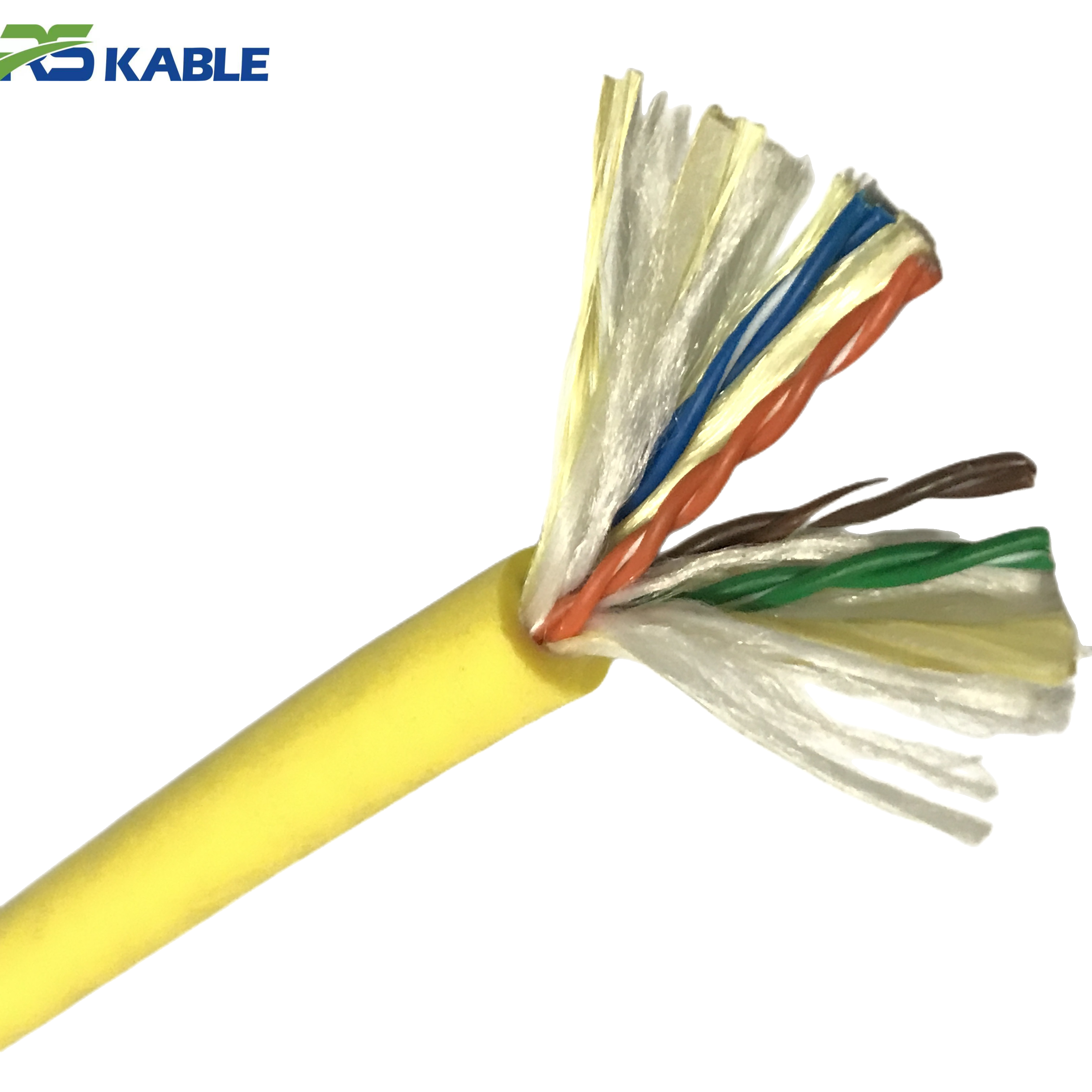
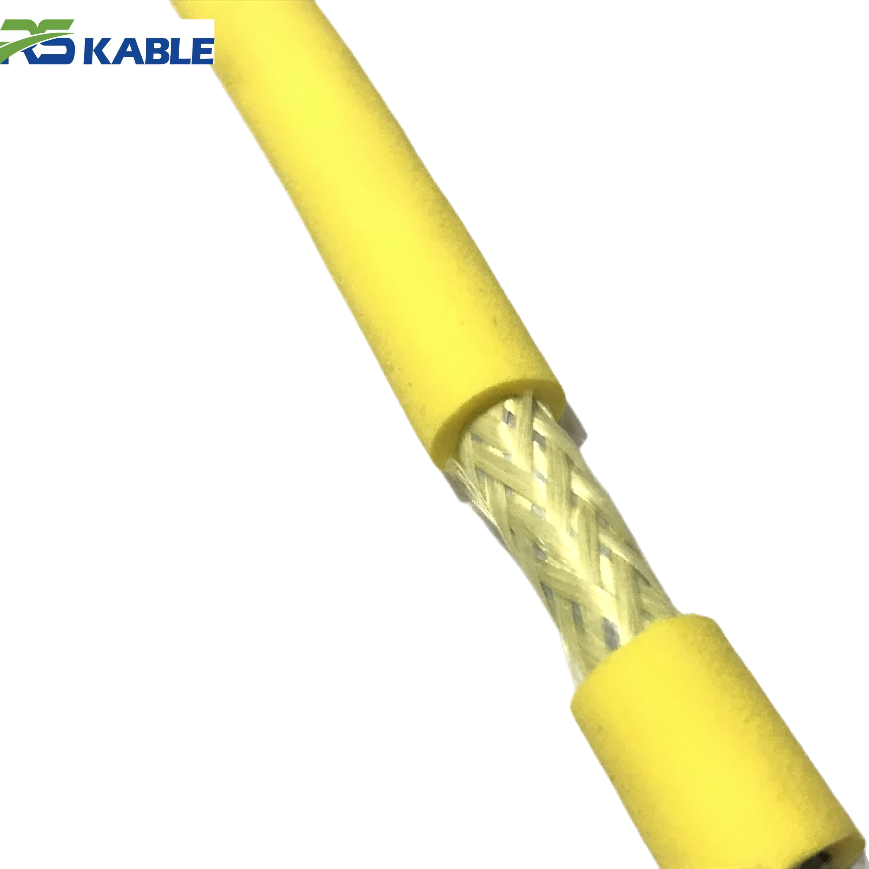
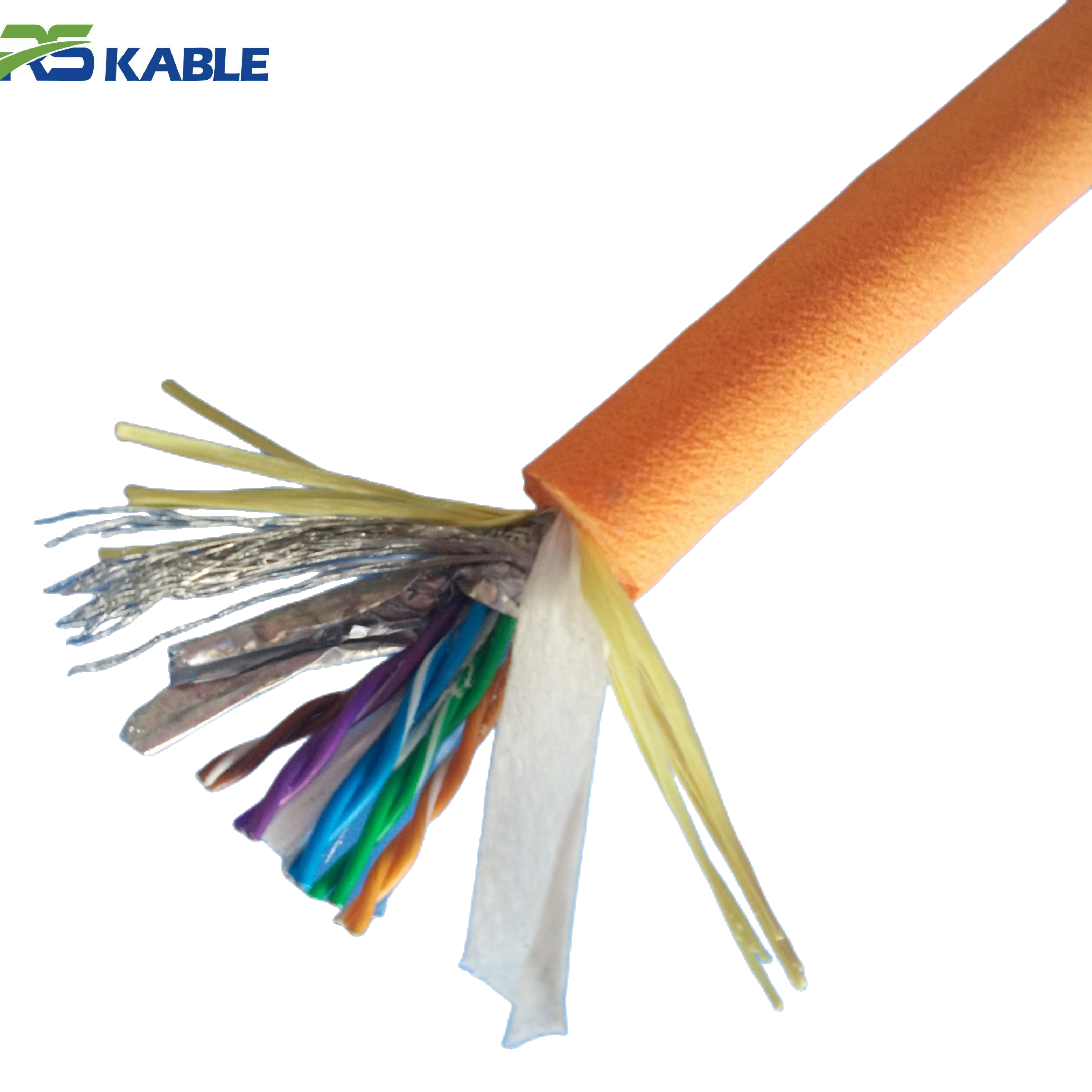
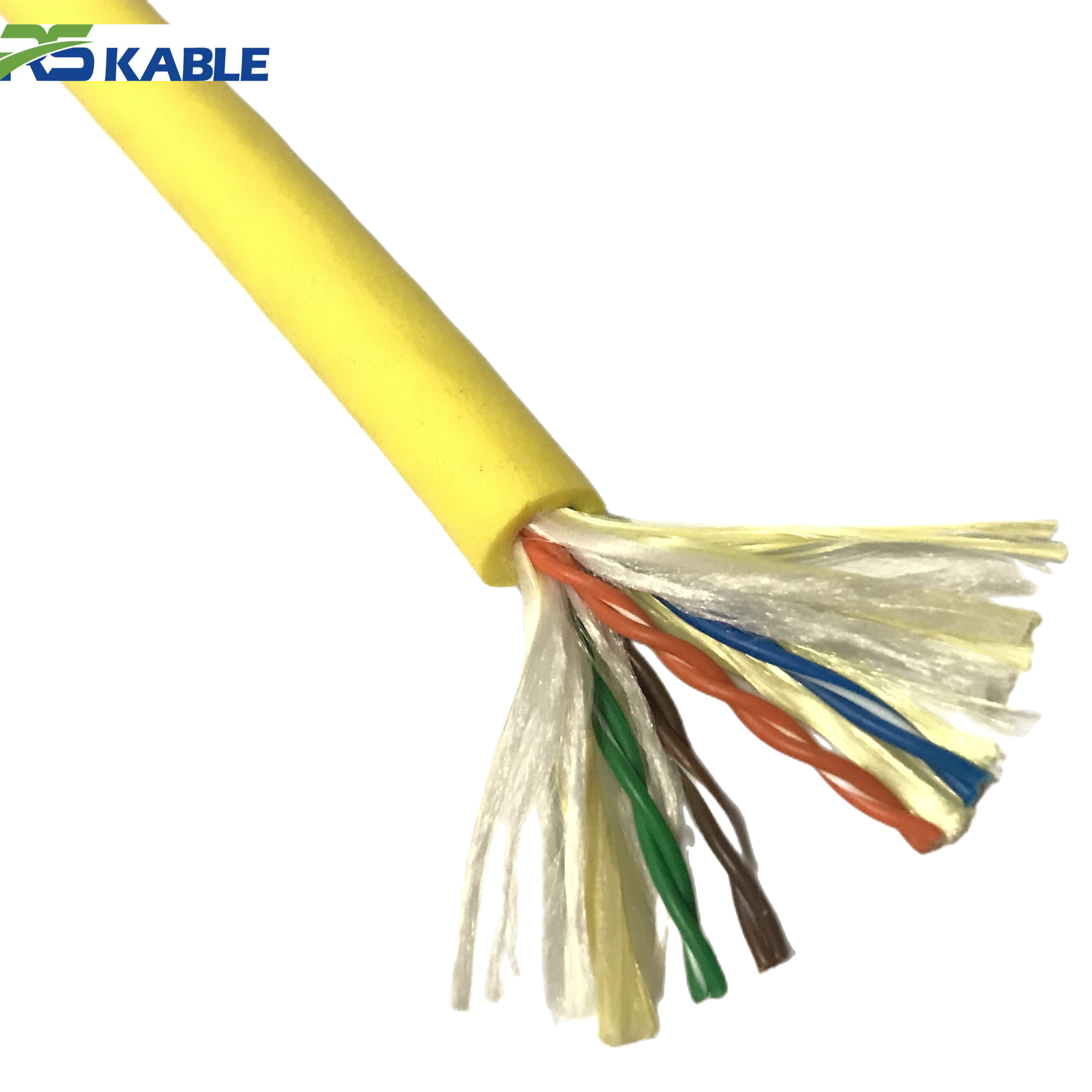
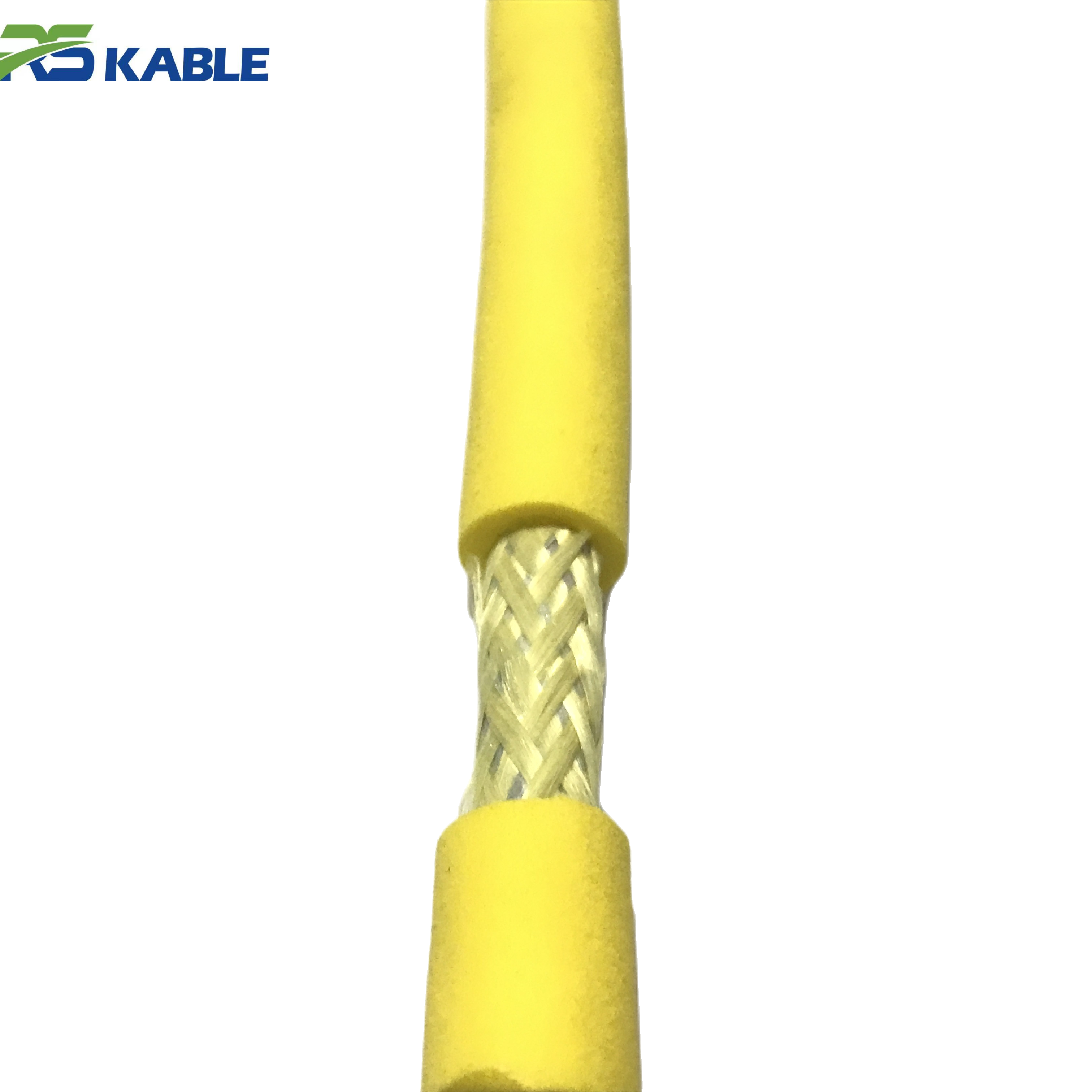
How fiber “survives” inside a tether (the architecture that matters)
Fiber is strong in tension when protected correctly, but sensitive to bending and crushing when mismanaged. A robust tether architecture typically includes:
-
optical fibers (single-mode or multi-mode depending on system design)
-
buffering/protection layers that reduce micro-bending risk
-
strength members that carry tensile load (fiber should not carry tension)
-
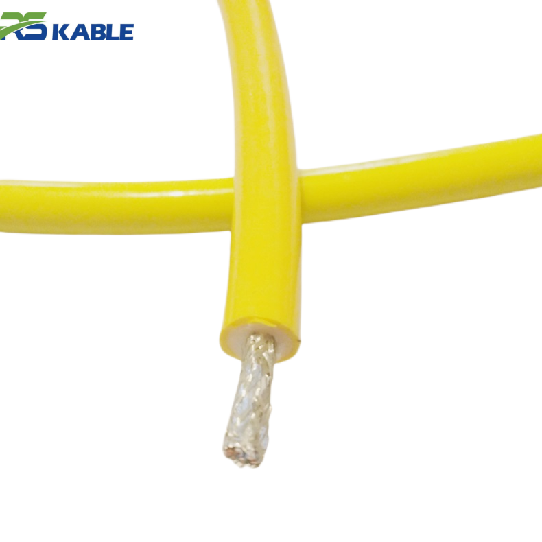
a jacket system designed for abrasion and seawater exposure
-
termination and strain relief that prevents bending concentration at the connector exit
Fiber reliability is not a material choice; it is a mechanical protection strategy.
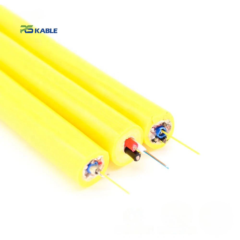
Fiber-only vs hybrid power + fiber (which one most teams use)
Fiber-only tether
Used when power is delivered separately or the system architecture places power elsewhere. Often seen in specialized setups.
Hybrid power + fiber tether
The most common practical solution because it:
-
delivers power for thrusters, lights, and tools
-
carries fiber data for video and telemetry
in one managed line.
When most teams say they want a fiber-based tether, they mean a hybrid ROV Cable with both power and fiber.
The most common dropout pattern: video fails during motion
Movement-only dropouts account for a large portion of real-world fiber complaints. They usually trace to one of four causes:
-
Micro-bending near the termination
Repeated bending at the same point causes intermittent loss during motion. -
Bend radius violations at routing points
Small sheaves, tight deck corners, or fixed bends gradually create a stress zone. -
Crush and hard-spot events
Over-tight spooling, pinch points, or crossing layers under load deform internal geometry. -
Strain relief mismatch
A strain relief that is too stiff or too soft can concentrate bending exactly where you don’t want it—right at the connector exit or sealing boundary.
Electronics swaps rarely fix these. Mechanical verification does.
A fast troubleshooting order that saves time
When the feed drops during movement but looks fine when stationary, use this order:
-
inspect termination zone for stiffness changes, cracks, or visible damage
-
inspect routing points (sheaves/fairleads/deck corners) for tight radius risk
-
check for hard spots or crush marks on the cable during payout
-
compare optical loss to baseline measurements
-
only after tether checks, investigate cameras, encoders, or topside gear
This order matches how most field failures actually behave.
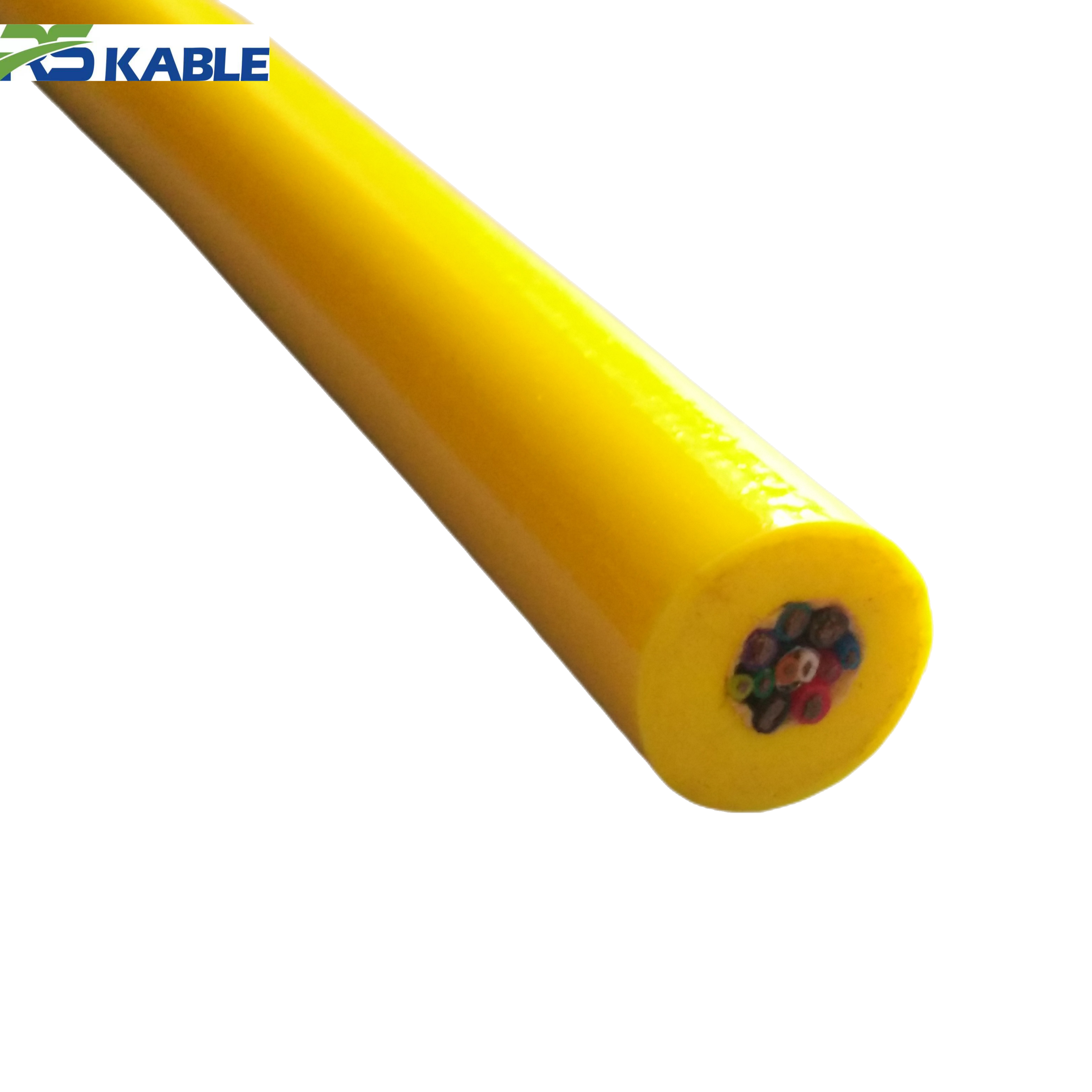
Fiber count planning: a simple template (avoid underspec and overspec)
Fiber planning should be practical, not theoretical. Use this template:
Step 1 — List today’s live requirements
-
number of live video streams
-
telemetry and control channels
-
sensor feeds that must be live (sonar, imaging, etc.)
Step 2 — Add modest expansion
Add margin for future sensors, but avoid “unlimited” because increased fiber protection can increase OD.
Step 3 — Check the OD/drag impact
If additional fibers force a larger tether diameter, consider whether drag and sweep zone will reduce mission efficiency in current.
A good fiber plan improves data without making handling worse. A balanced ROV Cable supports both.
What to include in an RFQ (fiber-specific items that prevent mismatches)
Include these items so vendors design for field stability:
-
fiber type and count
-
live video stream requirements and latency sensitivity
-
hybrid vs fiber-only architecture
-
confirmation that strength members carry tensile load (not fiber)
-
minimum bend radius requirement and routing constraints
-
termination and connector interface requirements
-
jacket environment description (abrasion, structures, debris)
-
acceptance testing requirements with documented baselines
If a quote does not include baseline testing expectations, troubleshooting later becomes slower and more subjective.
Acceptance baselines and “go/no-go” rules (make reliability measurable)
Fiber reliability improves dramatically when teams treat optical performance like a baseline metric.
What to record before first deployment
-
insertion loss baseline per channel
-
OTDR baseline if your workflow uses it
-
a simple record of date, length, and connector configuration
When to re-test (event triggers)
Re-test after:
-
a hard recovery
-
a snag event with noticeable tension spike
-
any kink/hard-spot discovery
-
any routing incident (pinch point or tight bend)
Go/no-go rules (practical, not academic)
-
if movement-only dropouts appear and loss differs meaningfully from baseline → isolate and inspect before further diving
-
if a hard spot is found → treat as a high-risk zone and re-test immediately
-
if connector contamination is suspected → clean, dry, then re-test rather than guessing
These rules turn “it feels worse” into verifiable decisions.
Operating habits that keep fiber stable for the long term
-
protect the first meters behind terminations during handling
-
keep bend radius compliance a deck-routing standard
-
avoid over-tight spooling that creates crush zones
-
prevent cable crossovers under load on drums
-
treat kinks and hard recoveries as maintenance triggers
-
keep connectors capped, clean, and properly stored
Most “fiber problems” are preventable with consistent handling discipline.
FAQ
Why does video drop only when the ROV is moving?
Because motion changes bending stress. The most common causes are micro-bending near terminations, routing bend violations, or crush damage that shows up under movement.
Do I always need OTDR testing?
Not always, but baseline insertion loss is strongly recommended. OTDR is useful when your operations rely on locating loss events along length.
How many fibers should I specify?
Start with today’s live video and telemetry needs, then add modest expansion. Avoid overspecifying if it increases OD and drag significantly.
Can a hybrid power + fiber tether be reliable?
Yes. Reliability depends on termination design, strain relief, routing, and handling—not on the concept of hybrid itself.
What is the most important acceptance step?
Recording baseline optical loss per channel before deployment and comparing after major handling or load events.