Common ROV Cable Failure Modes in Offshore Operations and Preventive Solutions
Offshore operations are built around reliability. Whether the task is subsea inspection, pipeline survey, intervention support, construction monitoring, or deepwater maintenance, the entire mission depends on stable communication between the vehicle and the surface. In that system, the tether is more than a connection line. It carries electrical power, video, telemetry, control signals, and often mission-critical data that operators need in real time. A reliable ROV Cable is therefore not just a component. It is one of the most failure-sensitive parts of the entire underwater system.
When cable problems happen offshore, the impact goes far beyond one damaged section of jacket or one weak connector. A failure may lead to power interruption, video loss, unstable thruster response, erratic sensor feedback, emergency recovery, or even mission cancellation. In real offshore campaigns, that can mean vessel delay, lost weather window, higher standby cost, and added operational risk. That is why experienced subsea teams do not wait for obvious failure. They focus on early signs, root causes, preventive inspection, and better cable handling practices.
This article explains the most common offshore tether and umbilical failure modes seen in real operations, why they develop, how to identify early warning signs, and what preventive steps actually reduce risk. If your team works with offshore ROV systems, subsea robots, or marine cable handling equipment, this guide is designed to be both practical and search-friendly.
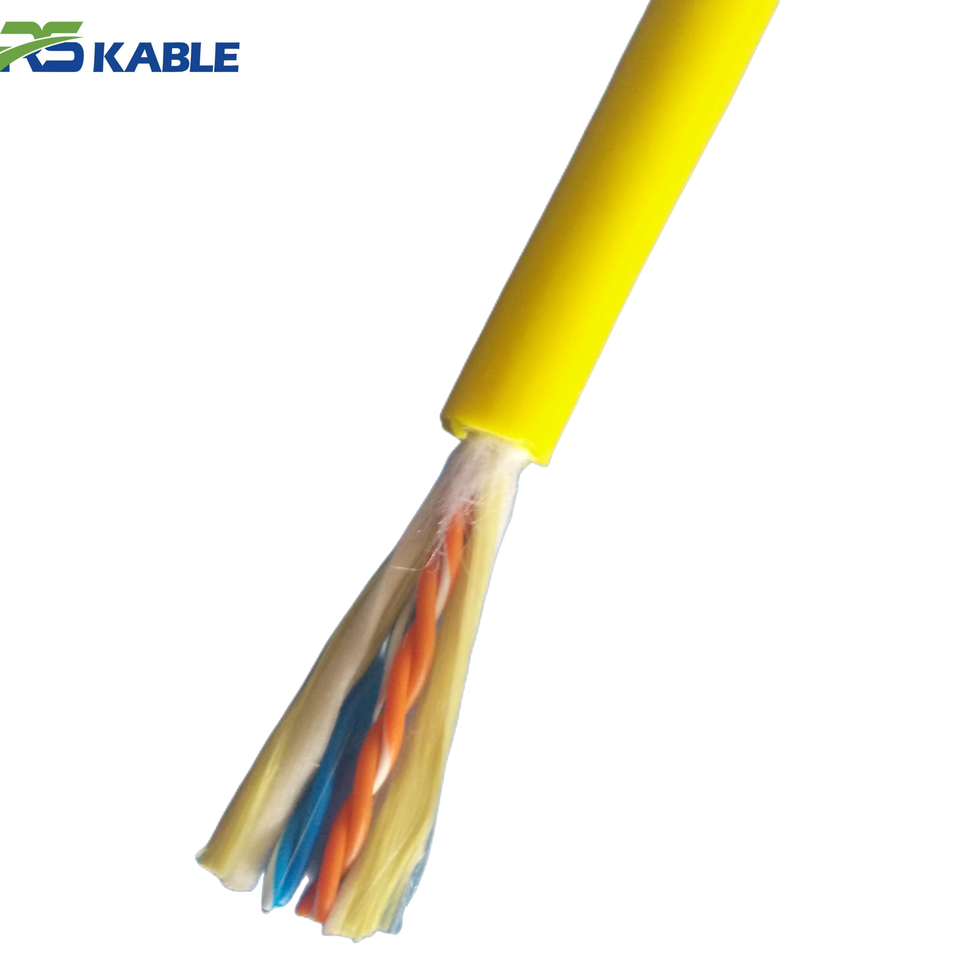
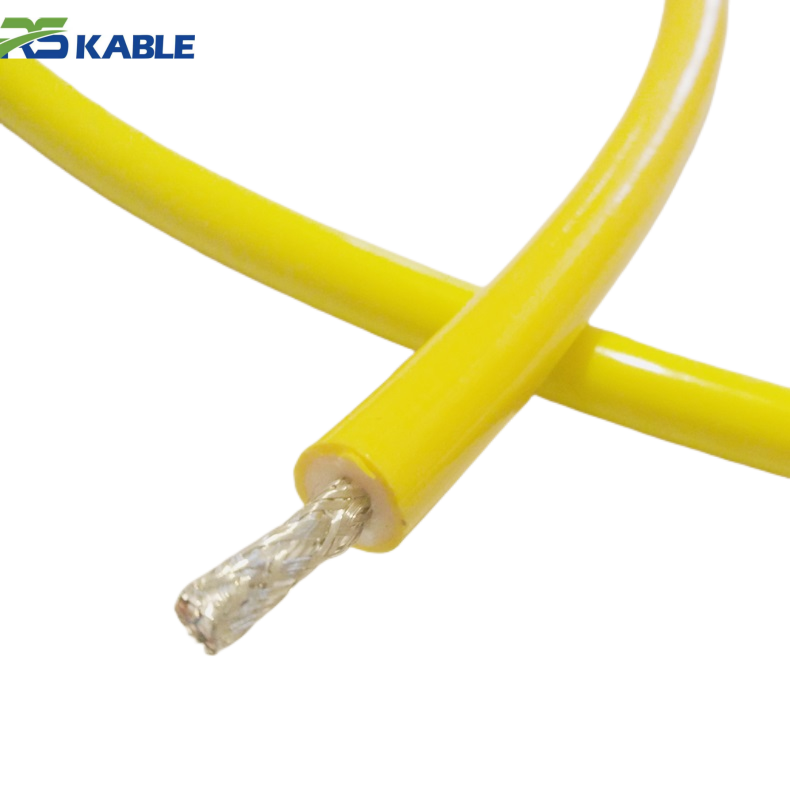
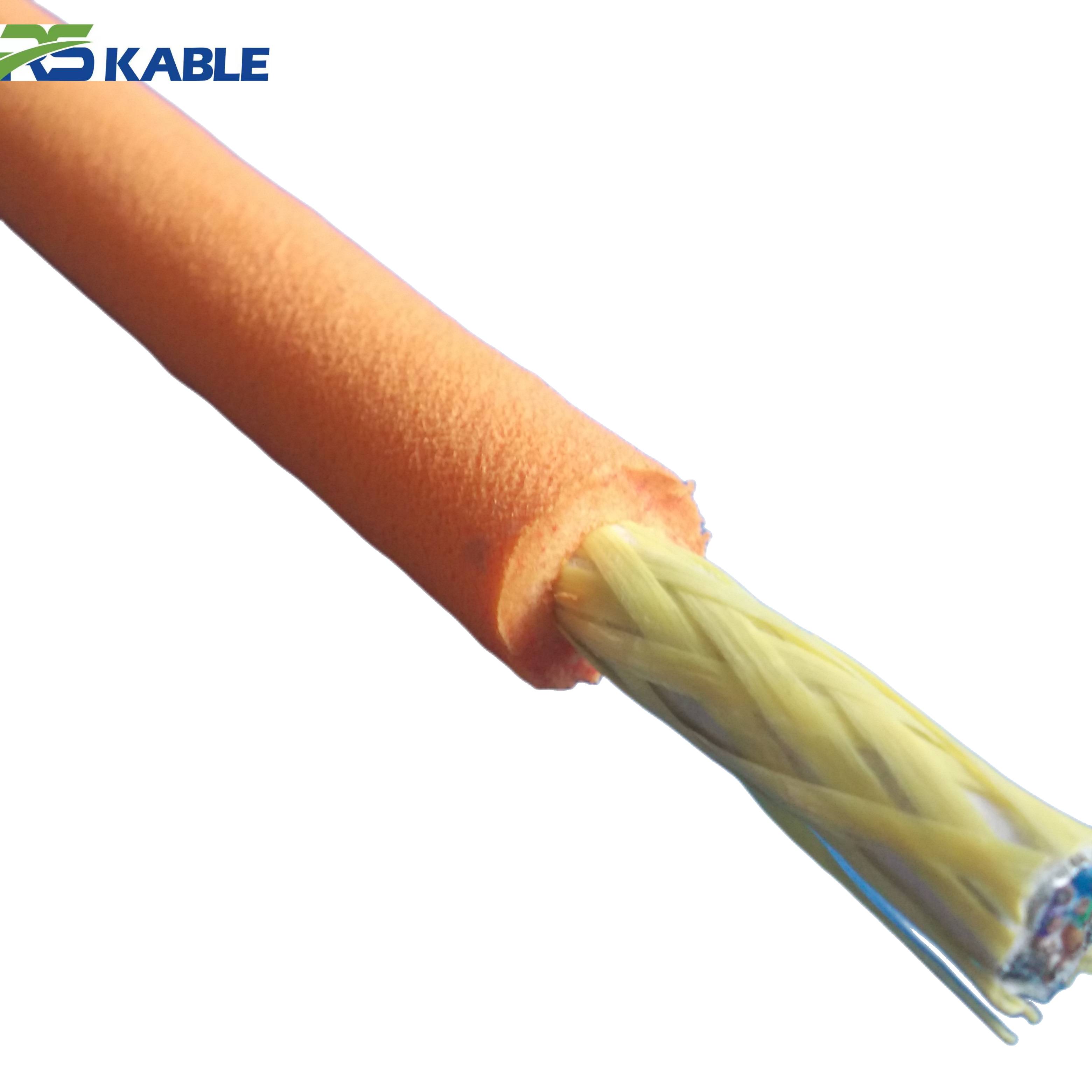
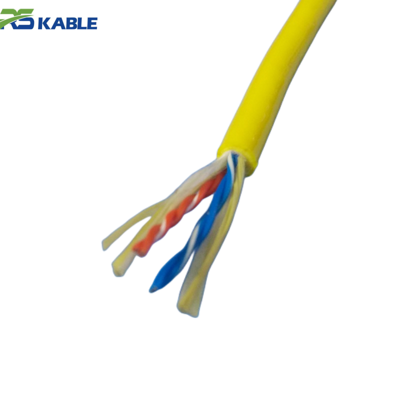
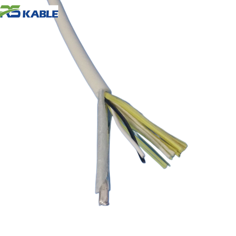
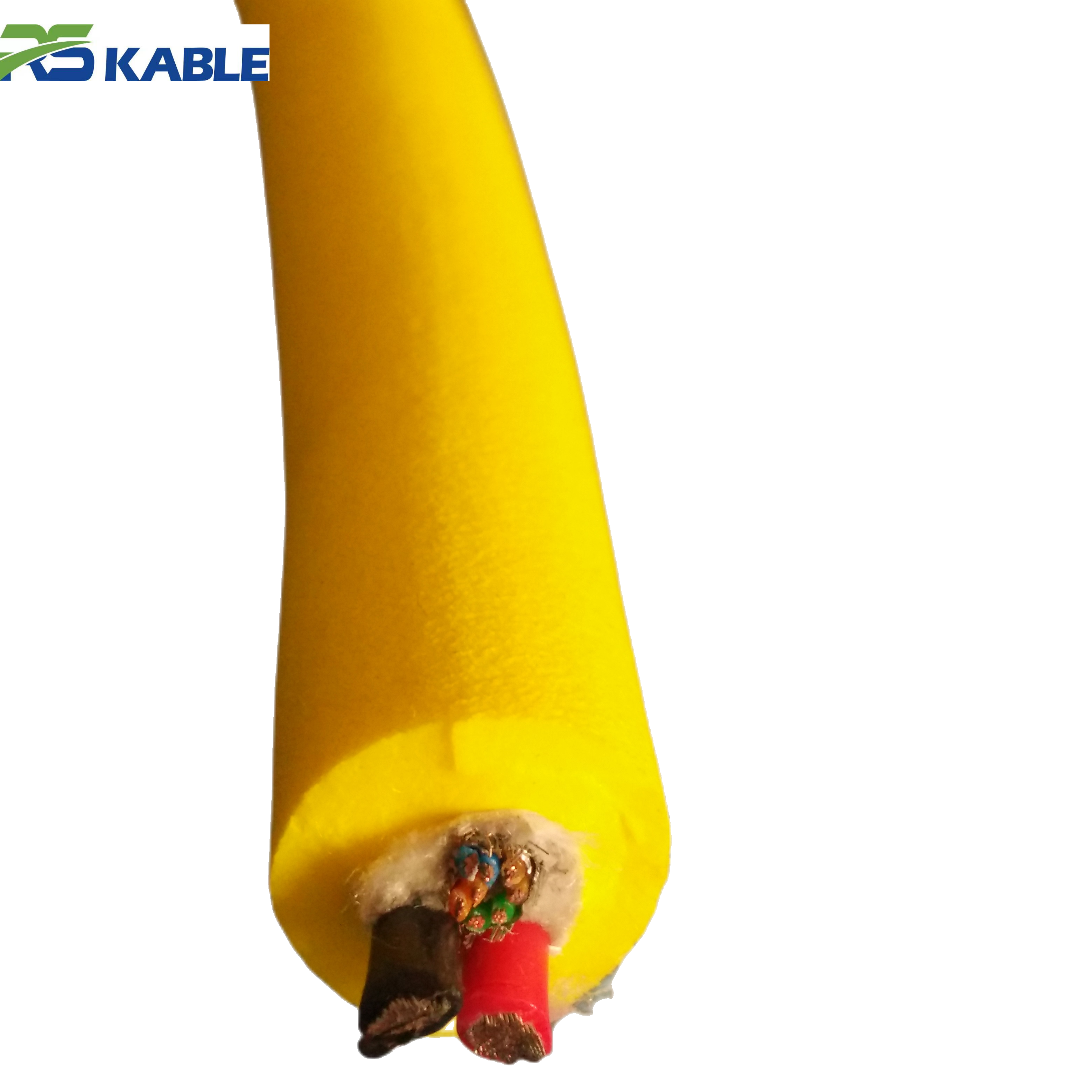
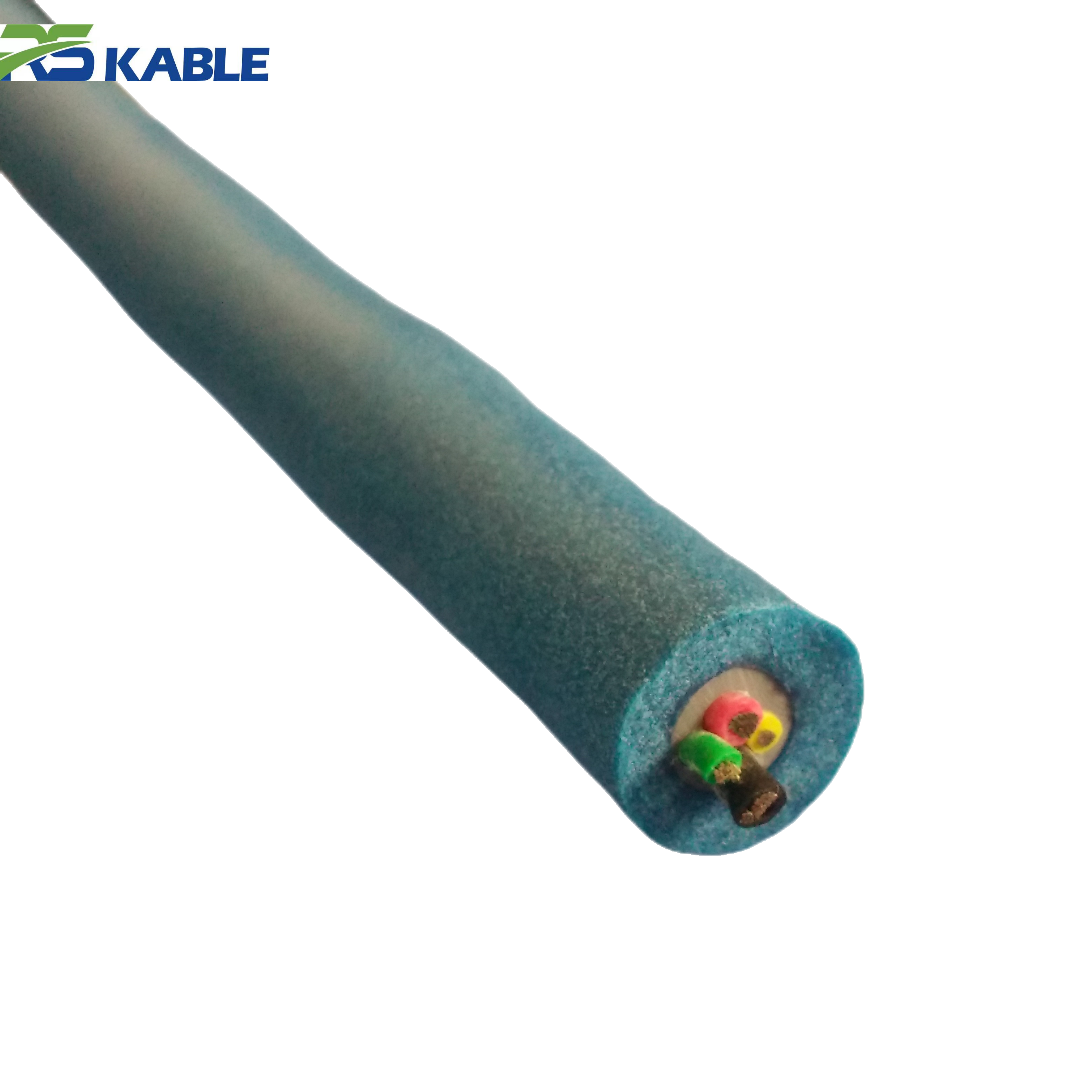
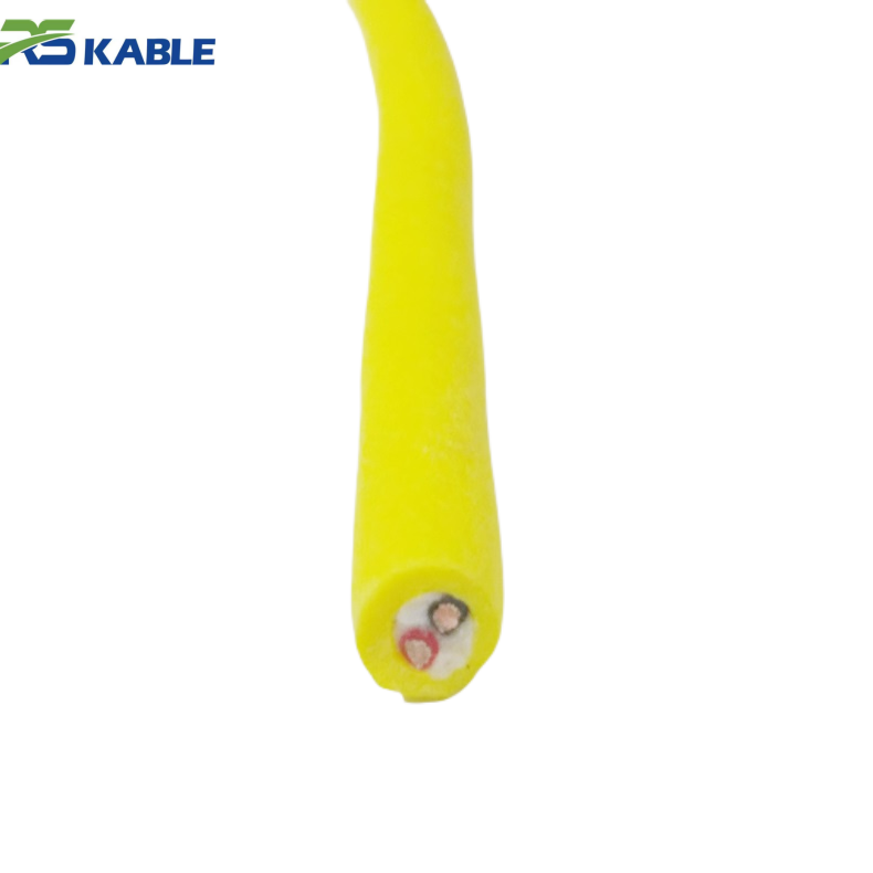
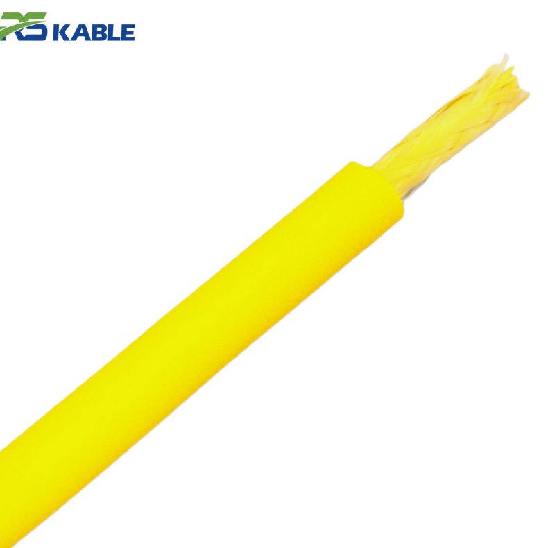
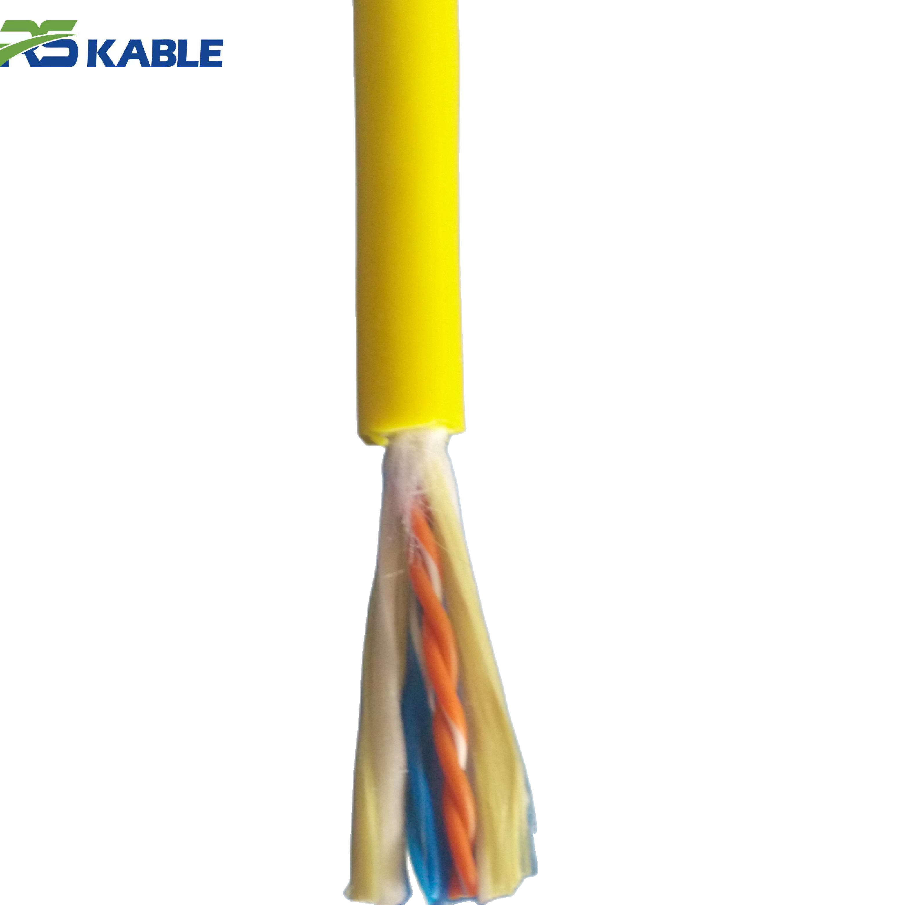
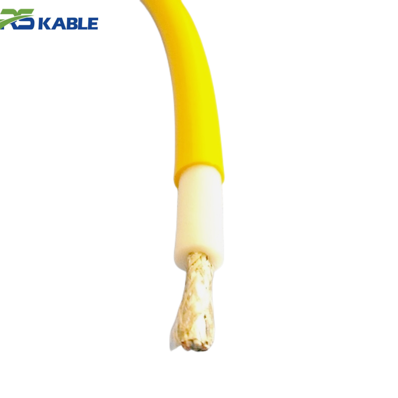
Subsea Pipeline Inspection ROV Cable – High Tensile & Pressure Resistance, Stable Power and Signal
This ROV cable is engineered for **subsea pipeline inspection** operations, featuring **high tensile strength**, **pressure-resistant construction**, and **EMI-shielded conductors** to ensure stable power delivery and high-fidelity signal transmission in demanding deepwater offshore environments.
Why Offshore Cable Failures Happen So Often
Offshore cable systems operate in a combination of stresses that few industrial products experience at the same time. A subsea tether may be bent repeatedly over sheaves, tensioned during launch and recovery, dragged across deck rollers, exposed to seawater and hydrocarbons, twisted by vessel motion, and compressed during poor storage. At the same time, it must still deliver stable power and clean signal transmission.
That is why most offshore cable failures are not caused by one dramatic event. They are caused by repeated smaller stresses that accumulate over time. Common contributing factors include:
-
Bending below the minimum recommended bend radius
-
Repeated abrasion at the same contact point
-
Poor spooling tension or uneven winding
-
Shock loading during launch and recovery
-
Water ingress from small jacket damage
-
Termination strain caused by poor support
-
Inadequate separation of power and communication elements
-
Delayed maintenance after early warning signs appear
In practical terms, most cable failures are progressive, not sudden. Teams that inspect early and document recurring damage patterns are usually the teams that avoid larger offshore incidents later.
Failure Mode 1: Outer Jacket Abrasion
One of the most common offshore cable problems is outer sheath abrasion. In many operations, this is the first visible sign of deeper cable health issues.
What causes jacket abrasion?
Abrasion occurs when the tether repeatedly contacts rough or sharp surfaces. Common locations include:
-
Deck rollers and fairleads
-
Launch and recovery systems
-
A-frame guide points
-
Vessel edges and steel structures
-
Subsea frames, pipelines, or guide posts
-
Seabed contact zones in shallow intervention work
Even a high-quality jacket will wear faster if the cable is forced through the same poorly aligned contact path during every deployment.
Early warning signs
-
Scratches, gouges, or roughened outer surface
-
Repeated damage at the same meter mark
-
Local flattening or jacket thinning
-
Surface discoloration or tearing
-
Increased drag when paying out or recovering the line
Preventive solutions
The best prevention starts before the vessel sails. Jacket material should match real offshore duty, not just basic electrical requirements. Polyurethane is often preferred because it combines abrasion resistance with flexibility. However, material alone is not enough.
Operational prevention should include:
-
Smoothing or replacing rough guide surfaces
-
Removing sharp edges from handling equipment
-
Checking recurring wear locations after each trip
-
Marking damage zones to identify repeat contact points
-
Re-routing the cable path if the same wear pattern appears repeatedly
In offshore practice, abrasion is often treated as unavoidable wear. In reality, repeated abrasion usually means the handling path needs correction.

Failure Mode 2: Internal Conductor Fatigue
A cable can appear acceptable on the outside and still be developing serious internal damage. Conductor fatigue is one of the most overlooked offshore failure modes because it often starts invisibly.
What causes conductor fatigue?
Conductor fatigue usually develops from repeated flexing, torsion, or tight bending during dynamic use. It is especially common when:
-
The cable passes over undersized sheaves
-
The reel diameter is too small for the design
-
The line is repeatedly bent in the same zone
-
The tether is used dynamically when designed mainly for static duty
-
Spooling tension is poor, causing internal movement and stress
Over time, copper strands begin to fracture. The result may be intermittent power problems long before total failure occurs.
Early warning signs
-
Intermittent thruster response
-
Power loss only during certain cable positions
-
Temporary signal or video interruption during movement
-
Local heat buildup in one section
-
Faults that disappear when the tether is straightened
Preventive solutions
Preventing conductor fatigue requires both good cable design and good handling discipline. Fine-stranded conductors usually perform better in dynamic marine applications than coarse-stranded ones because they tolerate repeated motion more effectively.
Prevention measures include:
-
Respect the specified minimum bend radius
-
Match the tether design to dynamic use if repeated movement is expected
-
Use correct reel and sheave diameters
-
Avoid tight temporary bends during deck handling
-
Add periodic electrical continuity testing to maintenance routines
If intermittent faults appear only when the cable moves, internal fatigue should be investigated before the next offshore campaign.
Failure Mode 3: Water Ingress
Water ingress is one of the most damaging failures in any marine electrical system. Once seawater reaches internal elements, the result can include corrosion, insulation breakdown, unstable signals, and eventual conductor damage.
What causes water ingress?
Water commonly enters through:
-
Damaged outer jacket
-
Cracked or poorly sealed terminations
-
Connector seal failure
-
Mechanical impact near the end of the tether
-
Neglected cuts that deepen over multiple immersion cycles
In offshore operations, a small surface defect can become a major electrical problem after repeated wet-dry exposure.
Early warning signs
-
Lower insulation resistance readings
-
Corrosion at termination hardware
-
Intermittent leakage or grounding alarms
-
Signal instability after immersion
-
Dampness or contamination near connector interfaces
Preventive solutions
Water ingress prevention depends on both cable integrity and termination quality. Many failures blamed on the cable body actually begin at poorly supported end terminations.
Best practice includes:
-
Inspect every termination before and after deployment
-
Use marine-rated sealing systems designed for pressure and immersion
-
Repair even small jacket cuts promptly
-
Include insulation resistance testing in preventive maintenance
-
Protect end sections from excessive bending and impact
A cable system is only as strong as its most vulnerable entry point, and offshore that entry point is often the termination.
Failure Mode 4: Tensile Overload
In deepwater work, the highest cable load often happens during launch, recovery, and vessel motion rather than during stable subsea operation. This makes tensile overload a major risk, especially in rough weather or long vertical deployment.
What causes tensile overload?
Common causes include:
-
Underestimating suspended cable weight
-
Shock loading from vessel heave
-
Snagging during recovery
-
Poor load transfer at termination points
-
Using a cable with insufficient working-load margin
-
Winch operation that creates sudden tension spikes
Early warning signs
-
Distortion or elongation near load-bearing sections
-
Unusual tension behavior during recovery
-
Damage concentrated near strength member transition points
-
Repeated faults after bad-weather deployment
-
Handling instability not seen in earlier campaigns
Preventive solutions
Load management should always consider both normal and dynamic conditions. Offshore teams should evaluate working load, peak load, shock load, and safety margin, not just theoretical static load.
Useful preventive measures include:
-
Monitor tension during launch and recovery
-
Train winch operators to avoid shock loading
-
Match reinforcement type to real depth and load profile
-
Confirm terminations are transferring load correctly
-
Review offshore procedures after every overload event
An overloaded cable may not break immediately, but it may lose a large portion of its remaining service life.
Failure Mode 5: Signal Interference and Data Instability
For modern subsea systems, data integrity is just as important as mechanical integrity. Offshore ROV operations now depend on stable video, sonar, telemetry, Ethernet, and control signals. If communication quality drops, the mission may stop even when power delivery remains intact.
When an ROV Cable starts to fail in the signal layer, the first symptoms often look like system or software problems rather than cable problems.
What causes communication instability?
-
Inadequate shielding between power and signal elements
-
Internal screening damage after crush or torsion
-
Water ingress affecting sensitive circuits
-
Termination corrosion
-
Poor hybrid layout in power-and-data tether systems
-
EMI exposure during high-load operation
Early warning signs
-
Video noise or intermittent image loss
-
Telemetry spikes or unstable sensor values
-
Delayed control response
-
Communication faults that worsen when power demand rises
-
Errors that appear after mechanical handling incidents
Preventive solutions
Signal-related faults are reduced by combining proper design with good maintenance.
Recommended actions:
-
Use cable structures designed for hybrid power-and-data transmission
-
Protect fiber and communication cores from crush damage
-
Inspect connectors for corrosion and contamination
-
Test data performance during scheduled maintenance
-
Investigate recurring signal faults before they become complete outages
If communication issues appear only during movement or under high electrical load, shielding or internal geometry problems may already be developing.
Failure Mode 6: Crush and Impact Damage
Offshore decks are busy, heavy-use environments. Cables are often stored near lifting gear, containers, tools, and vehicle hardware. A single impact or crush event can create long-term internal damage even when the outer jacket looks only slightly marked.
What causes crush damage?
-
Heavy equipment placed on stored tether sections
-
Cable trapped under reels or deck hardware
-
Dropped tools or subsea components
-
Poor transport support during mobilization
-
Uncontrolled deck traffic over exposed cable paths
Early warning signs
-
Flattened cable section
-
Sudden stiffness change in one local area
-
Localized jacket deformation
-
Power or signal issues after deck incidents
-
Repeated problems in storage zones
Preventive solutions
Prevention here is largely operational:
-
Keep dedicated routing paths for the tether
-
Never use the cable as general deck space
-
Store it on proper supports that maintain geometry
-
Inspect after any known impact event
-
Train deck crews that the tether is critical equipment, not general hose stock
Crush damage often becomes obvious only later, when internal elements begin to fail under reuse.
Failure Mode 7: Twist, Kink, and Poor Spooling
Twist damage is especially common in offshore operations where deployment must be fast. Poor spooling, uncontrolled payout, or manual correction of twisted sections can introduce torsional stress that leads to jacket wear, conductor fatigue, and handling problems.
What causes twist-related failure?
-
Uneven spooling tension
-
Repeated deployment without correcting cable memory
-
Manual handling that forces loops straight
-
Uncontrolled rotation during launch
-
Incompatible reel or handling alignment
Early warning signs
-
Cable tries to rotate during deployment
-
Loops or coils appear unexpectedly
-
Spiral-pattern jacket wear
-
Kink marks or local distortion
-
Increased difficulty in smooth payout
Preventive solutions
To reduce twisting risk:
-
Maintain even tension during winding
-
Avoid forced straightening of twisted sections
-
Align handling equipment properly
-
Inspect the reel build after every recovery
-
Train operators to identify early torsion before kinks form
Good spooling is not just housekeeping. It is part of cable life management.
Failure Mode 8: Termination and Connector Failure
In many offshore systems, the highest-risk location is not the middle of the tether but the end section. Connectors and terminations combine electrical contact, environmental sealing, mechanical support, and strain relief in one compact area.
What causes termination failure?
-
Poor strain relief
-
Excessive flexing near the connector
-
Weak sealing design
-
Corrosion in metallic hardware
-
Improper installation or rework offshore
-
Repeated side-load during deployment and storage
Early warning signs
-
Faults concentrated near cable ends
-
Visible corrosion, looseness, or cracking
-
Intermittent signal or power during end movement
-
Moisture traces near seals
-
Mechanical looseness under load
Preventive solutions
The best offshore teams treat terminations as scheduled maintenance items, not “fit and forget” hardware.
Recommended practice:
-
Use connector systems rated for actual marine service
-
Add proper strain relief at both ends
-
Prevent sharp bending close to the connector body
-
Inspect and clean connector interfaces regularly
-
Replace questionable seals before the next campaign, not after
Connector failure is expensive because it often appears suddenly after smaller warning signs were already visible.
How to Build a Practical Offshore Prevention Program
The best offshore teams treat ROV Cable management as a preventive discipline, not a reactive repair task. A strong program combines design review, operational control, inspection routine, and failure documentation.
A practical prevention program should include:
Pre-deployment checks
-
Visual inspection of jacket and high-wear zones
-
Connector and termination inspection
-
Bend-radius compliance check on reel path
-
Tension monitoring system check
-
Confirmation that rollers and fairleads are smooth and aligned
Post-recovery checks
-
Inspection of recurring wear points
-
Cleaning of contaminated sections
-
Logging of any new abrasion, cuts, or deformation
-
Functional testing if abnormal handling occurred
-
Immediate review after overload, snagging, or crush events
Scheduled maintenance checks
-
Continuity and insulation resistance testing
-
Signal performance or optical transmission checks
-
Termination integrity verification
-
Inspection of reel, sheaves, and deck routing hardware
-
Review of failure patterns by meter mark or deployment condition
This type of routine improves both reliability and lifecycle cost.
FAQ
What is the most common offshore ROV cable failure mode?
Outer-jacket abrasion is one of the most common problems because offshore handling exposes the tether to steel edges, rollers, and repeated friction.
Can internal conductor damage happen without visible external damage?
Yes. Repeated bending and torsion can break internal strands even when the outside of the cable still looks acceptable.
Why are offshore cable terminations such common weak points?
Because they combine sealing, strain relief, mechanical load transfer, and electrical connection in one area, making them more sensitive to installation and handling errors.
How can I reduce water ingress risk in marine tether systems?
Inspect jacket damage early, maintain connector seals, protect end terminations from stress, and include insulation resistance testing in routine maintenance.
What is the best preventive strategy for offshore cable reliability?
Use the correct cable for the duty cycle, control bend radius and tension, inspect high-wear zones, maintain terminations, and document repeat damage patterns.